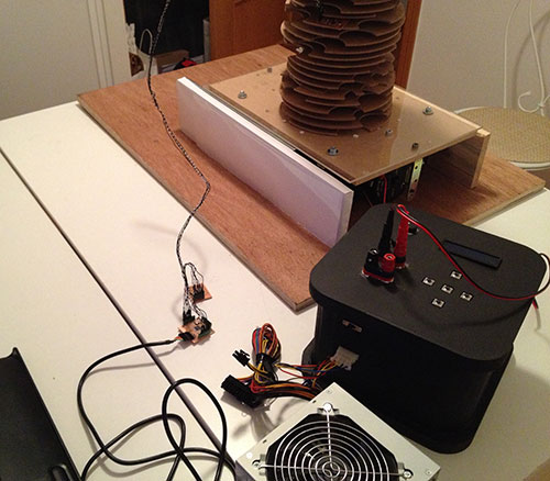
The idea is to build a shake table to simulate ground motion during an earthquake for the School of Architecture at Madrid based CEU San Pablo University, so that architectural students could explore how to minimize damage and improve their architectural designs.
The project also includes the design and construction of some structural models so that using this earthquake shake table, it will be possible to visualize data about the behavior of a structure thanks to the use of some sensors (accelerators). Once the model is located on a shake table, weights could be attached to each floor and the roof. Sensors are attached to the shake table and to the top of the building. The results of shake table testing (acceleration versus time of the shake table and the top of the building as the shake table is moved back and forth) can be monitored on the computer screen.
Due to the complexity of the project it will be developed by two students: Covadonga Lorenzo and Epifanio L. Cueva. The work will be divided at is shown below:
1.-Computer aided design
Epifanio L. Cueva: to design the function generator box.
Covadonga Lorenzo: to design the shake table and some structural models.
2.-Physical design and fabrication
Epifanio L. Cueva: computer controlled machining for the function generator enclosure (CNC).
Covadonga Lorenzo: computer controlled machining for the shake table (CNC) and computer controlled cutting (laser cutters) for models.
3.Electronics design and production
Epifanio L. Cueva: design and production of the function generator board and the buttons board.
Covadonga Lorenzo: design and production of the Fabduino, two boards for the accelerators and one board for the LED array
4.Input and Output devices
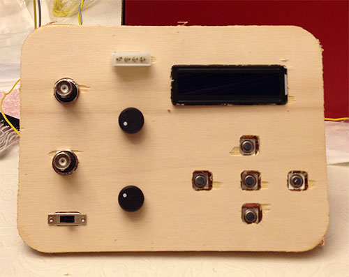
Epifanio L. Cueva: to design and make at least one input (control buttons of the function generator) and one output (LCD screen).
Covadonga Lorenzo: to design and make at least one input (two accelerators) and one output (led array)
5.Embedded programming
Epifanio L. Cueva: program the function generator.
Covadonga Lorenzo: to program the sensors attached to the structural models (two accelerators) and the Fabduino
Introduction
After analyzing references and examples of different earthquake tables we decided to design and make our own shake table model.
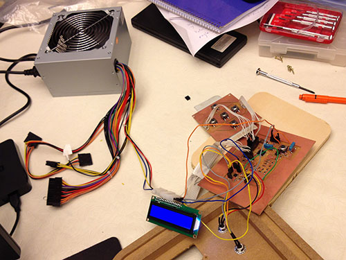
The table has a shake platform, we move it with two mechanical wave drivers and we use a function generator to move them.
The function generator is an electronic equipment design to generate a variety of simple repetitive waveforms.
Function Generator can be divided in two categories:
- Analogue function generator. This type of function generator circuit can be built easy but they have stability and accuracy problems.
- Digital function generator. This type generate the waveform for a single fixed frequency reference clock and it is converted to analog signal with a digital to analog conversor (DAC).
This method is called Direct Digital Synthesis or DDS.
Because it generates the waveform with a digital circuit, it has very good stability, accuracy and reproducibility compared to the analog function generator, and can be fully controlled by software.
For our project we choose to build a DDS function generator
.
The function generator is based on Mindaugas Marozas DDS v2 function generator.
Function generator main features:
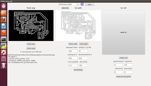
- Single sided PCB. I have designed a single side PCB so I can mill the board in the Modela.
- Almost 100% SMD components.
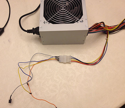
- External modify PC ATX power supply.
It requires +5V, -12V, +12V and GND voltages.
-12V and +12V are used for offset and amplitude control.
I have had to modify a PC ATX power supply unit where all required voltages are available.
It is necessary to modify the 20-pin Molex connector to do the protection circuit, and modify one 4-pin Molex connector to add -12V voltage.
|
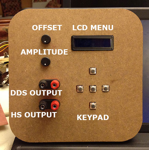
- Dedicated High Speed [1 to 8 MHz] (HS) square signal output. HS signal is direct output from Atmega16. - Dedicated DDS outpout. DDS signals are sine wave, square wave, sawtooth wave, reverse sawtooth wave, triangle wave and ECG wave.
An R-2R ladder is used as a simple and inexpensive way to perform the digital-to-analog conversion and it is adjusted via LM358N offset and amplitude regulating circuits. Offset and amplitude can be regulated by two potentiometers. Offset in range of +5V to -5V (POT1) and amplitude in range of 0 to 10V (POT2). DDS frequency range is 0-65534Hz
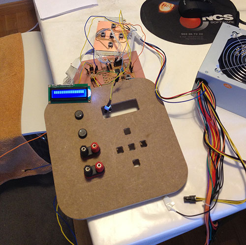
- LCD menu. The frecuency can be adjusted in 1, 10, 100, 1000 or 10000 Hz steps - Five button keypad
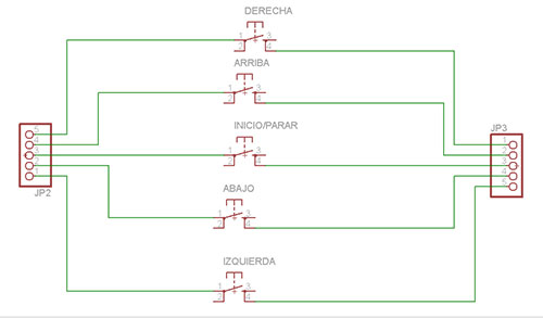
Up and down buttons are used for browsing menu while left and right buttons are used for changing the frequency value. There is also a separate menu for changing frequency step.
When the middle button is pressed, the signal generation starts. Middle button is pressed again for stopping the signal.
Components list
Part |
Value |
R1 |
470 Ω ½W 5% |
R2 |
10 ΚΩ ¼W 5% |
R3 |
100 ΚΩ ¼W 1% |
R4 |
20 ΚΩ ¼W 1% |
R5 |
20 ΚΩ ¼W 1% |
R6 |
10 ΚΩ ¼W 1% |
R7 |
20 ΚΩ ¼W 1% |
R8 |
10 ΚΩ ¼W 1% |
R9 |
20 ΚΩ ¼W 1% |
R10 |
10 ΚΩ ¼W 1% |
R11 |
20 ΚΩ ¼W 1% |
R12 |
10 ΚΩ ¼W 1% |
R13 |
20 ΚΩ ¼W 1% |
R14 |
10 ΚΩ ¼W 1% |
R15 |
20 ΚΩ ¼W 1% |
R16 |
10 ΚΩ ¼W 1% |
R17 |
20 ΚΩ ¼W 1% |
R18 |
10 ΚΩ ¼W 1% |
R19 |
20 ΚΩ ¼W 1% |
R20 |
100 Ω ¼W 5% |
R21 |
100 ΚΩ ¼W 1% |
R22 |
12 ΚΩ ¼W 1% |
R23 |
150 Ω ¼W 5% |
POT1 |
1 ΚΩ linear potentiometer |
POT2 |
47 KΩ linear potentiometer |
POT3 |
10 ΚΩ trimmer |
C1 |
100 nF MKT/polyester |
C2 |
100 nF MKT/polyester |
C3 |
18 pF ceramic |
C4 |
18 pF ceramic |
Q1 |
16 MHz crystal |
IC1 |
ATMEL ATMEGA16AU |
IC2 |
LM358N |
BNC1 - BNC2 |
connectors |
S1 - S5 |
Push button |
LCD |
HD44780-based 2×16 character LCD |
ISP |
Male header 2x3 for ISP |
POWER |
Female headers for power
PIN1 : +12V
PIN2 : -12V
PIN3 : GND
PIN4 : +5V |
ON/OFF |
on/off switch |
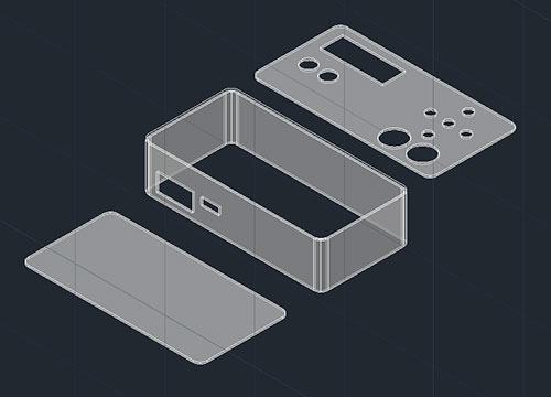
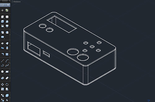
1.-Computer aided design. Design of the function generator box.
I used Autocad to draw all the pieces and to model a 3D drawing that help me to test the dimension and location of all of them.
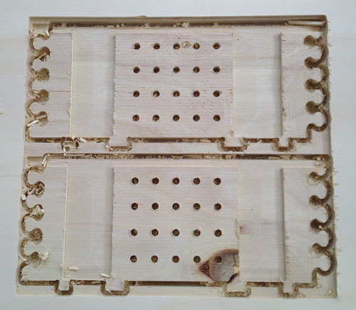
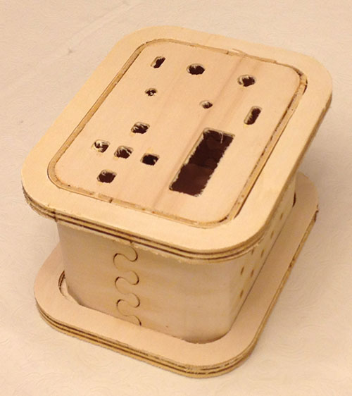
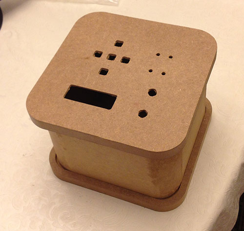
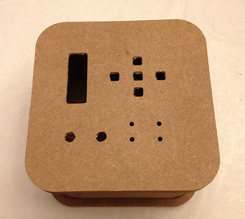
2.-Physical design and fabrication. Making the function generator box.
I used the CNC machine to cut the box.
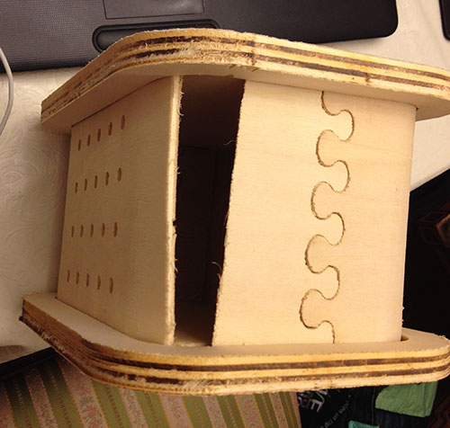
The first box I made had two parts for the sides.
One of them broken when I was putting the parts together.
It broke in one corner.
I think problem was that the flutes were not very deep.
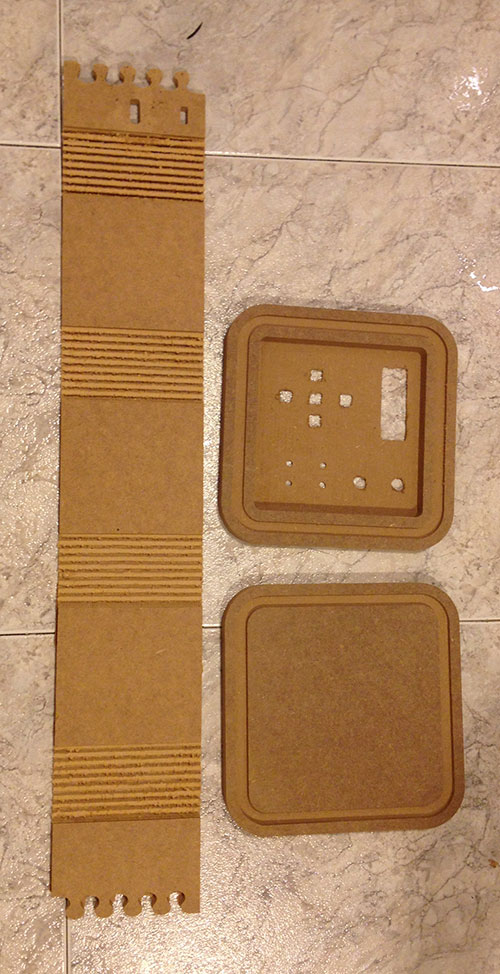
I designed the new box using VcarvePro.
I made the flutes more deeper and now the sides are only one piece.
I also have changed the position of some buttons and connectors.
3.Electronics design and production.
Design and make the function generator board and the button board.
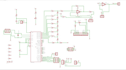
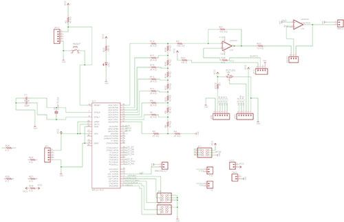
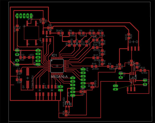
I have designed two boards with Eagle for the function generator.
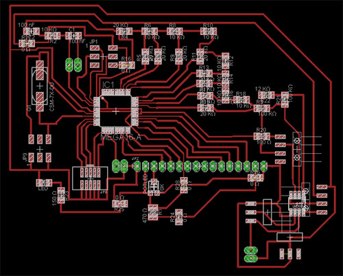
Function generator board
Eagle's autorouter was not able to route the board so I have routed it manually
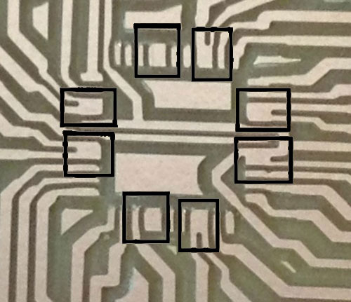
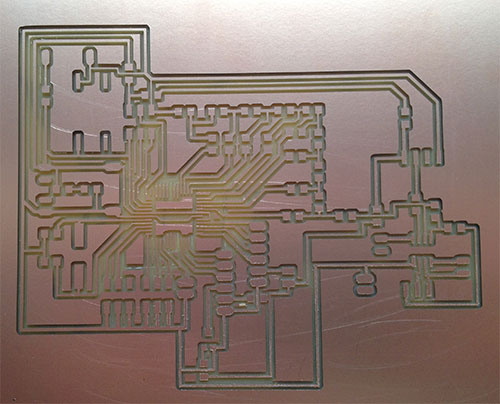
My first attempt was a failure. The Modela could not drill all processor pads, and some connectors pads were too small for the connectors that I have..
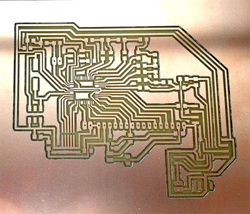
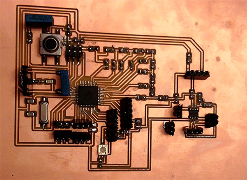
After I changed some connectors pads I made a second attempt with the Modela.
4.Input and Output devices.
A five buttons keypad is the input device of my project and I have used a LCD display as an output device.
I have used
AVR-GCC 4 bit and 8 bit LCD library. This lirary allow to use four pins to control the LCD display.
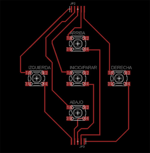
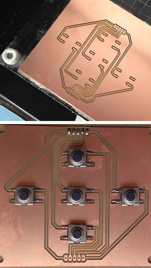
Keypad board
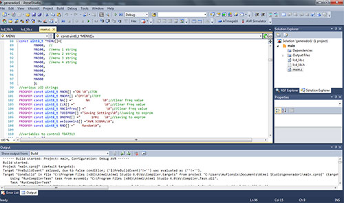
5.Embedded programming Program the function generator
I have used Mindaugas Marozas firmware as point of departure. It is written in C with some parts on ASM code. I have not changed ASM part because I do not know this language.
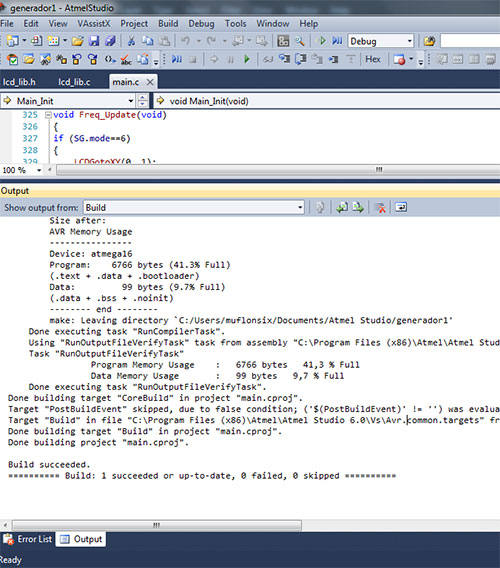
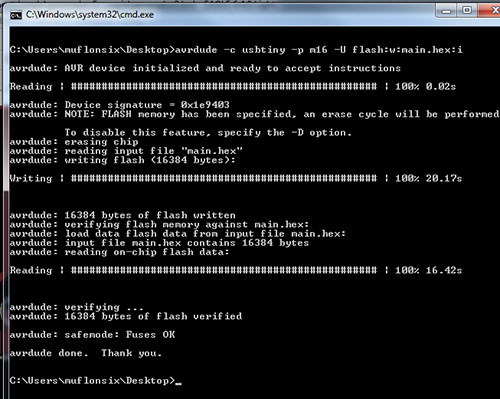
Bulding the project
Before you upload .hex file to the board you should set ATMEGA16 fuses.
The ATMEGA16 fuses should be :
HIGH = 0×59
LOW = 0xCF
avrdude -c usbtiny -p m16 -U lfuse:w:0xcf:m
avrdude -c usbtiny -p m16 -U hfuse:w:0x59:m
Final files:
basetapa.dxf
laterales.dxf
botones.sch
botones.brd
generador.sch
generador.svg
main.c
|