Output devices
This week's assignment was to build and program a circuit to control something.
(to produce an output)
What I decided to build:
Knowing that my final project is going to comprise of both Stepper and DC motors, and maybe servo motor, I decided to play around with understanding how these work and how to program them to fit my needs. I started with Prof. Neil's Stepper motor control board (the full step). I chose to play around with the board that comprises of the PWM IC. this was intended for me to get to understand how the PWM's work, since it is my first time working with them. As for the transistor based circuit, I already have knowledge as to how they work so I focused on the PWM's IC's.
How Challenging it was:
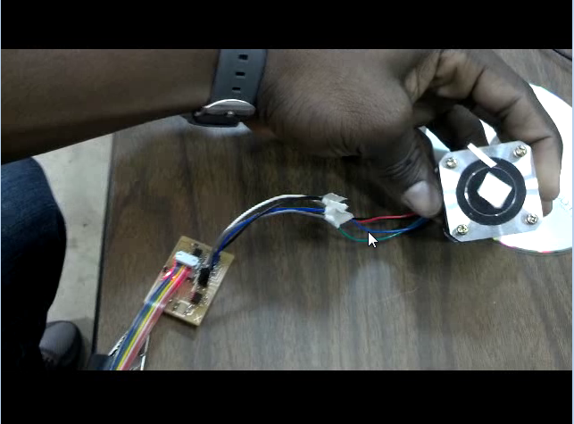
With the experience from the previous tasks, I did not have to do mach concerning the software issues, Once everything has been set, I just programmed it and there was no error returned. That was the good news. Now comes the bad news, after programming I was surprised to realize that, the motor I was going to use has different color codes. This challenged me to find and configure the wires in other to have it working. But before I did that I checked the outputs of each pin to make sure the circuit works. after some few tries, I succeeded in getting it to work.
Design process:
With this circuit, I really did not do much in modifying it, I just downloaded Prof. Neil's design for the class archive and redesigned it by adding a few more components to it. I then milled it with the Modella MDX. using the Fab Module. it only took a few minutes to get it done (milled). I then soldered it by first tinning the board and soldering the components by basically heating the lead on the board which flows and climb the lead of the component. Anyway I finished soldering it then programmed it with the C code and the Make file I downloaded from the archive.
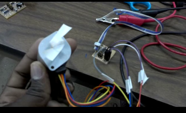
After this, I worked on figuring out how to connect the wires for the stepper motor.
I also took sometime to work on the Unipoler motor controller and it worked out just fine. The end product can be located below in video format.
Images Showing the process:
1) Downloaded circuit board file from class archive:

2) Image of my version of the board in eagle format ....
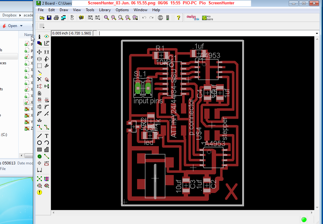
3) Processed curcuit in PNG format

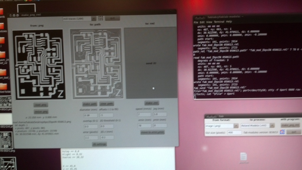
4) Processed PNG files with the Fab Module:
3) Milling and cuting the board:

4) Soldered the component to the board:

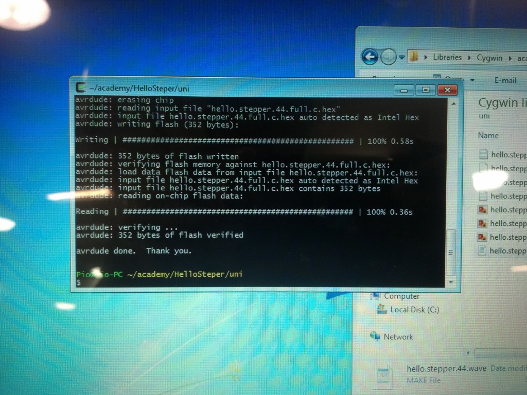
5) Programmed the board:
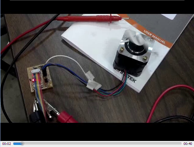
7) Wired the board to the motor and Tested them:
Click on images below to play