8. Electronics Production
For this week we had to:
-
Group assignment:
- Characterize the design rules for your in-house PCB production process: document feeds, speeds, plunge rate, depth of cut (traces and outline) and tooling.
- Document your work to the group work page and reflect on your individual page what you learned
-
Individual assignment:
- Make and test the development board that you designed to interact and communicate with an embedded microcontroller
Group assignment
As part of the group task, we considered the following points:
-
Software VPanel for SRM-20 for CNC control
-
Zeroing the XY and Z axes
-
Installing and fixing the new board on the MDF table
-
Generated G-codes for milling tracks and cutting out the board outline
-
We considered such parameters as the choice of cutter for work, the speed of rotation and movement of the spindle, the depth of milling and the depth of cut by the cutter.
-
Considered the structure of the G-code together.
-
Made a cut of the test board
The details of our group work can be found here.
Cutting the test board
During the group task, we learned how to work on a CNC Roland SRM-30 machine. We uploaded the .png files and using mods generated the necessary g-code to perform the milling process.
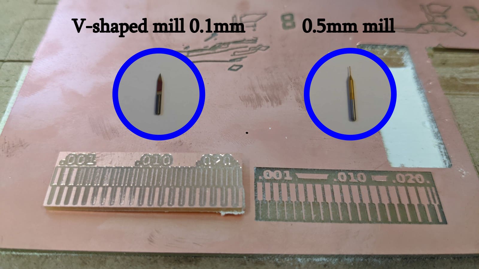
The initial test involved using a 0.5mm cutter to determine the maximum clearance it could pass, which was 0.020 inches.
We then switched to a 1/32” contour cutter.
We also tested the 0.1mm V-Cut. We saw how the cutter was able to travel a greater distance despite its V-shape.
Individual assignment
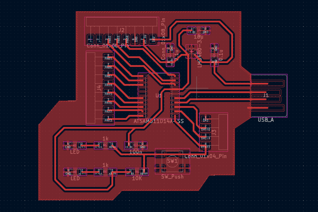
In my individual task, I decided to cut out the board that I designed during the Electronics Design week.
Export SVG files from KiCad
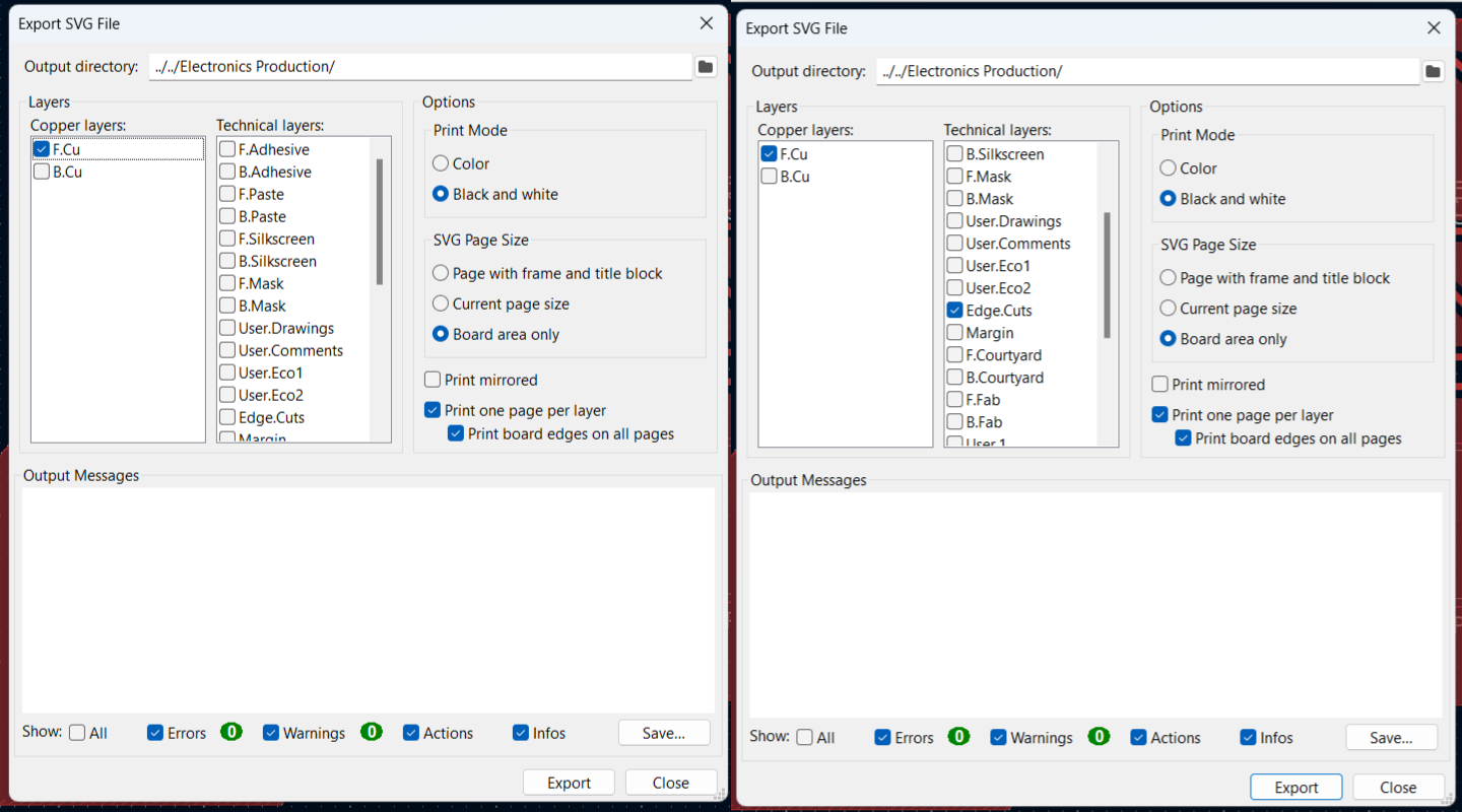
I did not change anything in my board design, but decided to print it as is. In order to generate G-code we need to export our layout in SVG format. To cut the board, we need to export two files: one for milling tracks and the other for milling a contour.
G-code for track milling
To generate G-code I decided to use Fab Mods. Here it is possible to generate G-code using files of different formats. I am using SVG format as drawing.
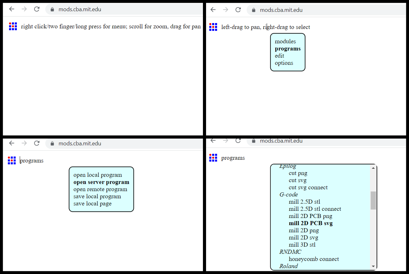
Then the program for generating the G-code will open. In the first window you need to select a file. Since the SVG file that is exported by KiCad has color in the paths, we need to invert the file because the milling path follows the black tracks.
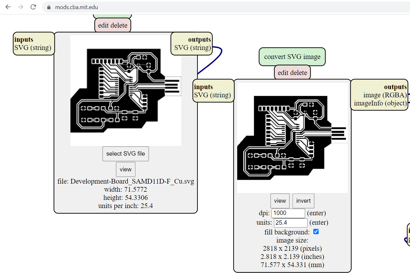
The next step in the third window is to select the type of operation, in this case, select mill traces (1/64). In the fourth and fifth window, you can change some parameters. I do not change the parameters and click on calculate, G-code will be generated and automatically downloaded to the computer.
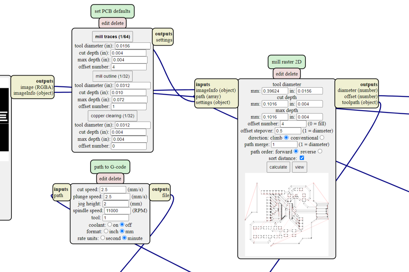
The trajectory of the cutter can be viewed in detail by clicking on view.
G-code for contour cutting
Now let’s generate a G-code for cutting out the board outline. The difference is that, for obvious reasons, inverting is not required.
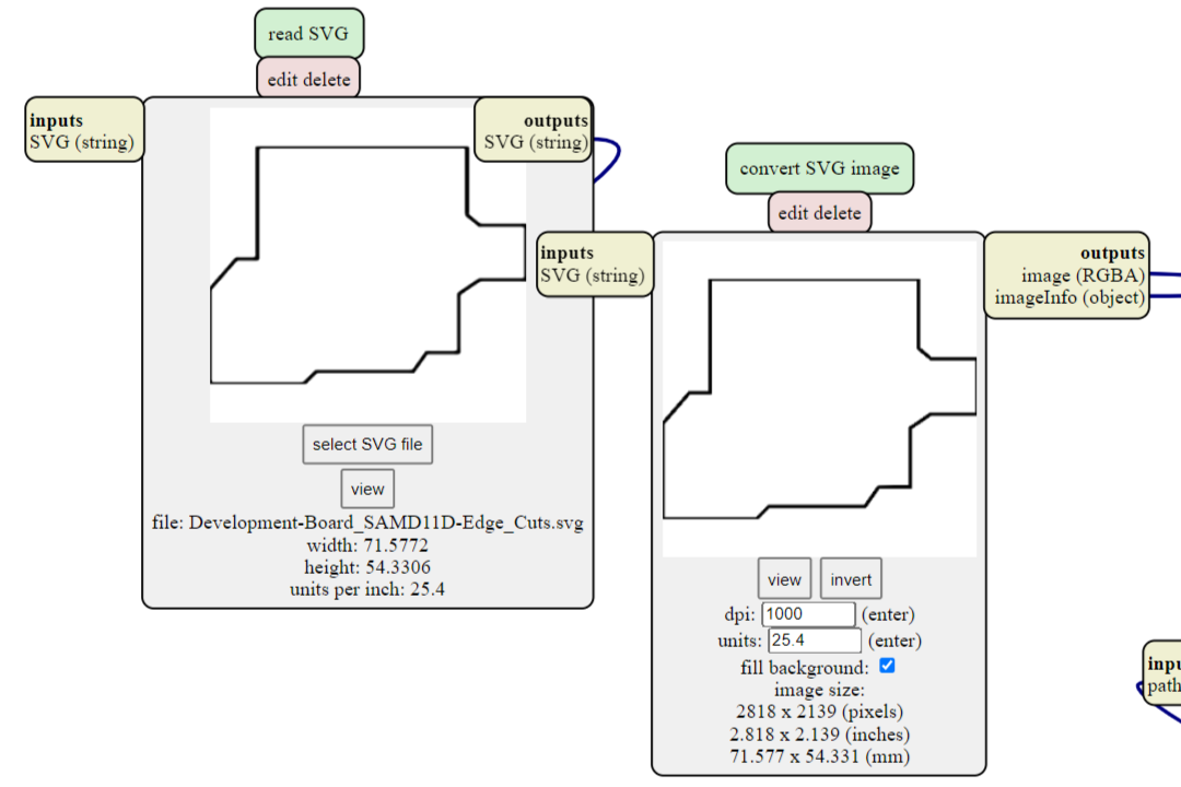
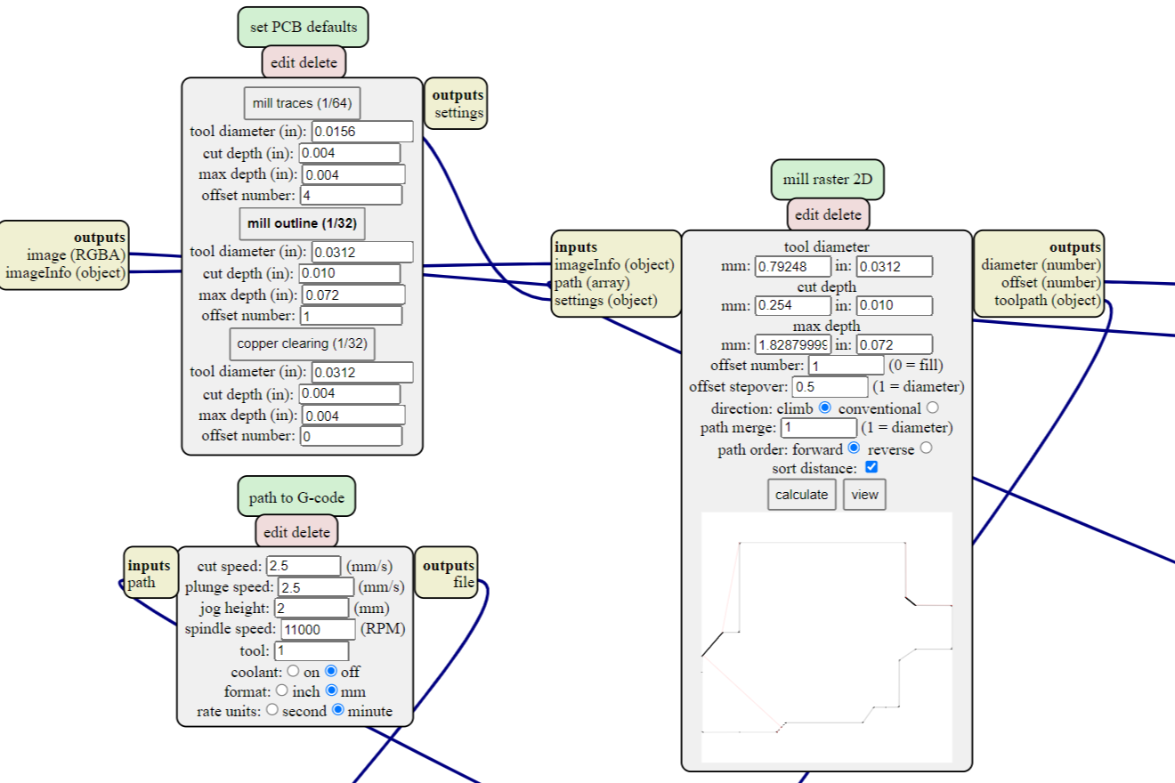
Then, in the third operation window, select mill outline (1/32). The settings can be left as default.
Work on Roland SRM-20
Once you have the G-codes, you can start working with the Roland SRM-20.
Attaching material to the sacrificial table
To fix the board on the working surface of the table, we use double-sided tape. But for secure fastening, we also use clamps. We fix the board on the sacrificial table with double-sided tape, then fix it with clamps for 15-30 minutes.
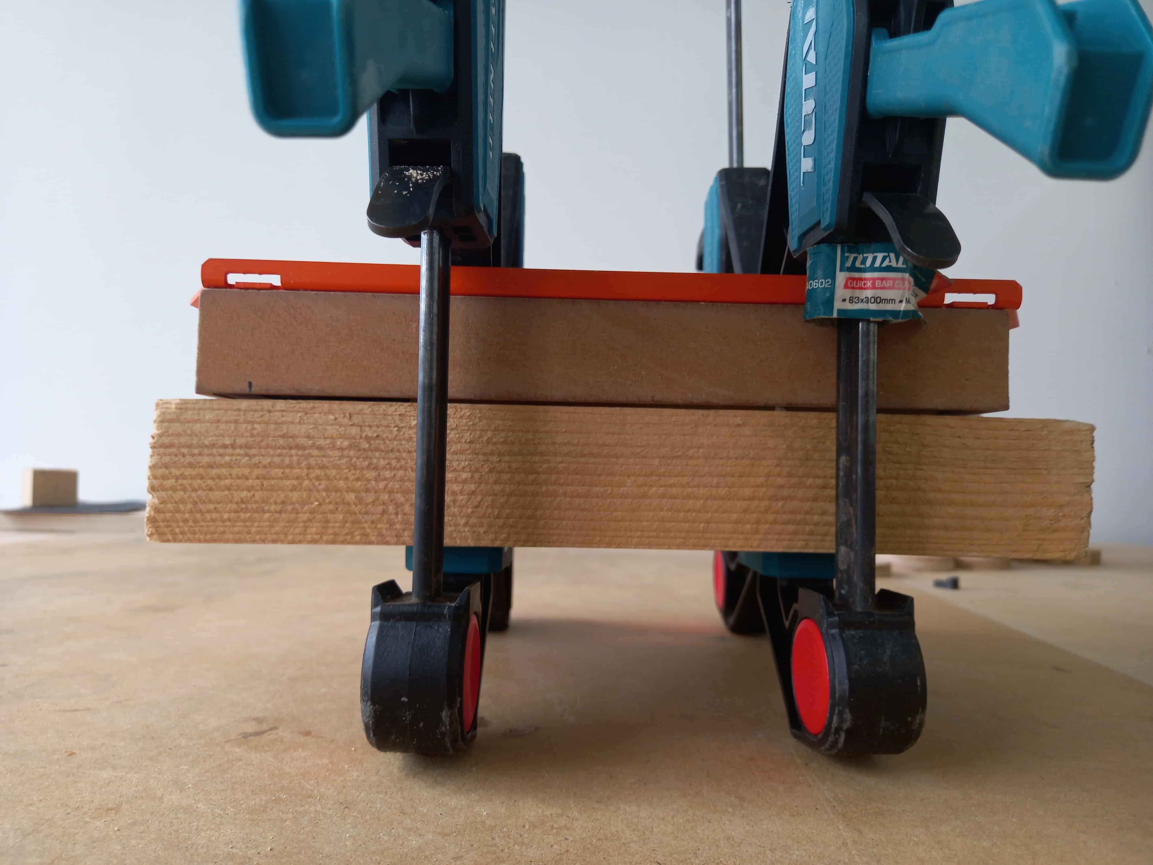
As a result, the board is securely fixed to the table surface.
Determination of zero levels for XY and Z coordinates
After the material is fixed on the table, we open the VPanel from SRM-20 program to control our CNC machin.
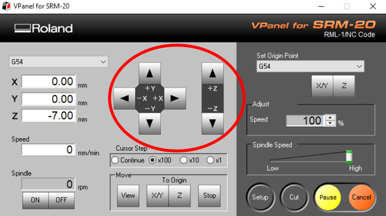
The CNC machine control program contains buttons for moving the spindle in various directions. These buttons allow you to adjust the position and orientation of the spindle to work on the workpiece.
In the next step, I send the spindle to the right place along the X / Y coordinates and zero its position along the corresponding axes. This can be done by clicking on the X/Y button in the Set Origin Point section.
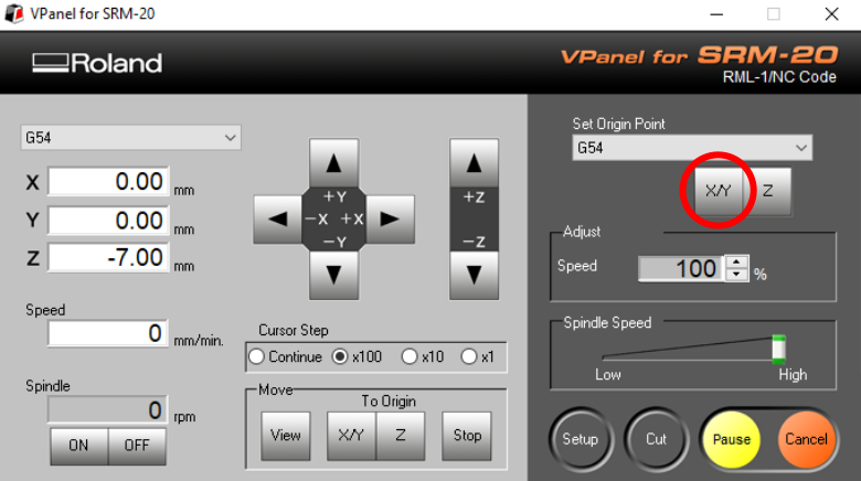
This program has the ability to work with several G-codes at once. Pressing the X/Y button resets the XY coordinates for the G54 system. From the list, you can select a different value from G54 to G59, which allows you to work in six different coordinate systems. However, it should be borne in mind that when running several files, the same cutter is used for processing.
After we have defined the XY start point, it’s time to define the Z zero point.
To do this, you must perform the following steps:
-
Raise the spindle to a safe distance.
-
Loosen cutter clamp.
-
Replace the cutter with the correct one.
-
Without clamping the cutter, release the spindle to the desired distance so that the cutter is sufficiently inserted into the spindle.
-
After replacing the cutter, fix it to the spindle and reset the Z-axis value.
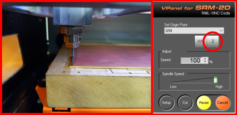
- For safety, you can raise the instrument after zeroing.
“It is necessary for the surface of the fixed board to be clean and for the tip of the milling cutter to be clean as well. Since we only deepen into the surface by 0.1mm when milling traces, and the copper layer of the board is 0.07mm, even a small amount of dirt can cause the zero position of the milling cutter to be at a certain distance from the surface of the board, which can result in incorrect milling (traces not separating).”
Track milling
After the material is fixed on the table, and the zero levels are determined, press the Setup button. A window opens where we can upload our file for milling tracks.
As I noted earlier, it is possible to upload several files at once, you need to make sure that the list contains the file or files we need.
After loading the G-code we need, click on the Output button, after which a pop-up window may open in which it is warned, it is recommended to stop working. This is due to the fact that the machine has standard settings for the speed of rotation and movement of the spindle, if the speed settings that are given in the G-code increase the standard ones, then such an error pops up.
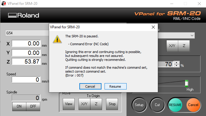
In my case, I will ignore this error and press the Resume button, besides, for safety, I reduced the speed of the cutter to 70%. After pressing the button, the milling of the tracks of my board will begin.
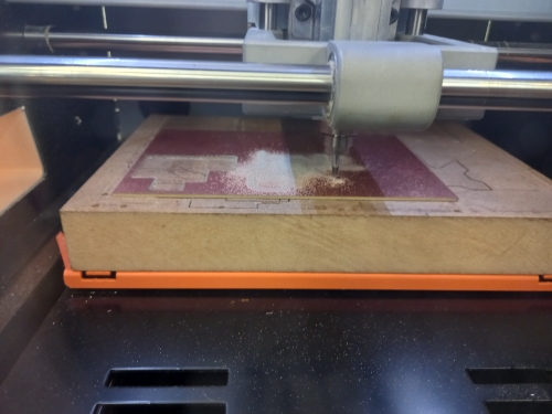
It is important to note that during the operation of the machine, it is necessary to monitor the process and avoid emergency situations, such as tool breakage, tool going outside the treated area, etc. In the event of errors, stop the machine immediately and eliminate the cause of the error.
Contour cutting
After milling the tracks, it remains to cut out the outline of the board.
To do this, you need to do the following steps:
-
To do this, the first step is to replace the 1/64 inch cutter with a 1/32 inch.
-
We send the spindle to the (0, 0) value, and there we determine the zero value of the Z axis.
-
And then we load the G-code for cutting the contour, and start the CNC.
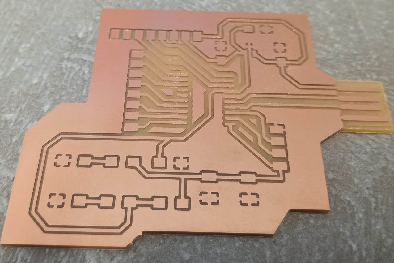
Result
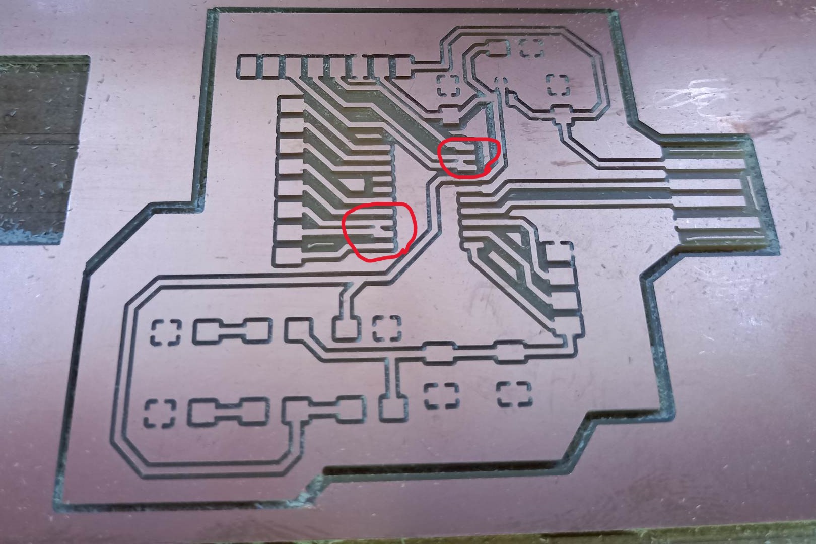
As a result, the board was cut out, I really liked the quality of the engraving and the quality of the cutout. The only thing that was cut out incorrectly was that two spaces between some tracks were cut out incorrectly.
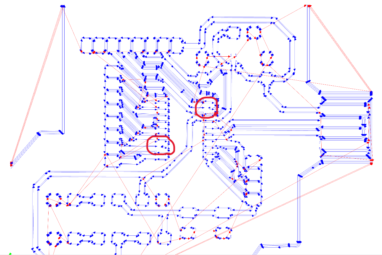
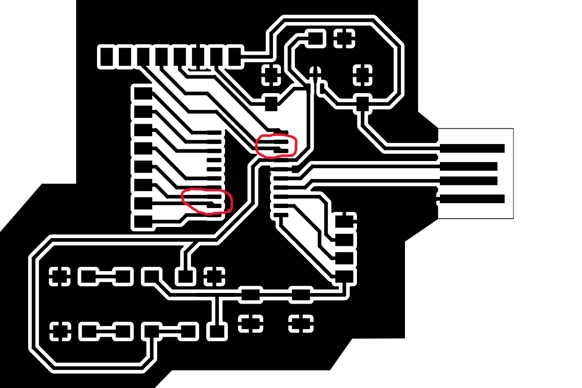
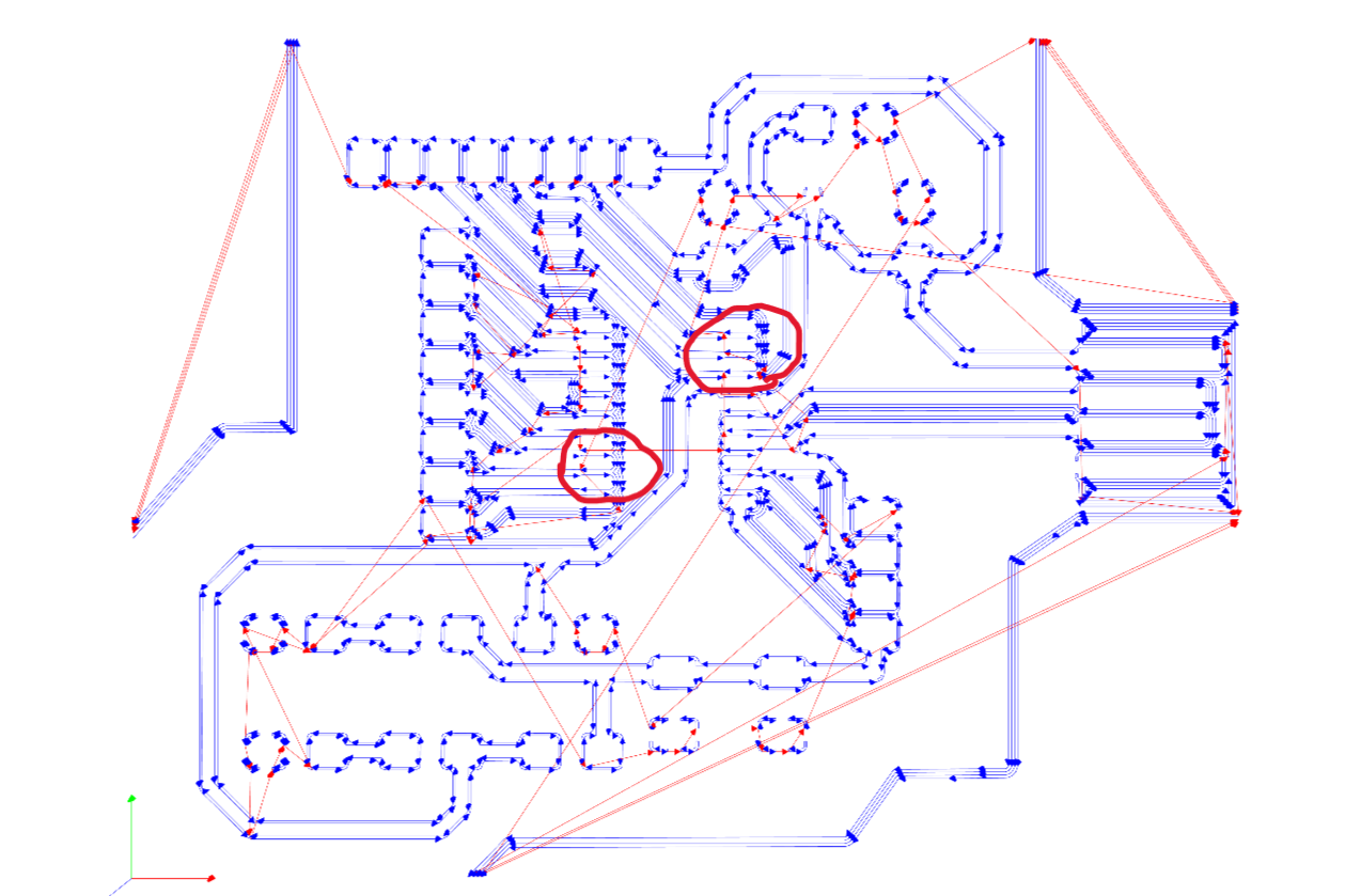
If you open it directly in the G-code generator, you can see the following
But there is another way to view the generated G-code, this can be done at ncviewer.com.
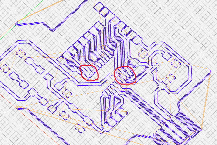
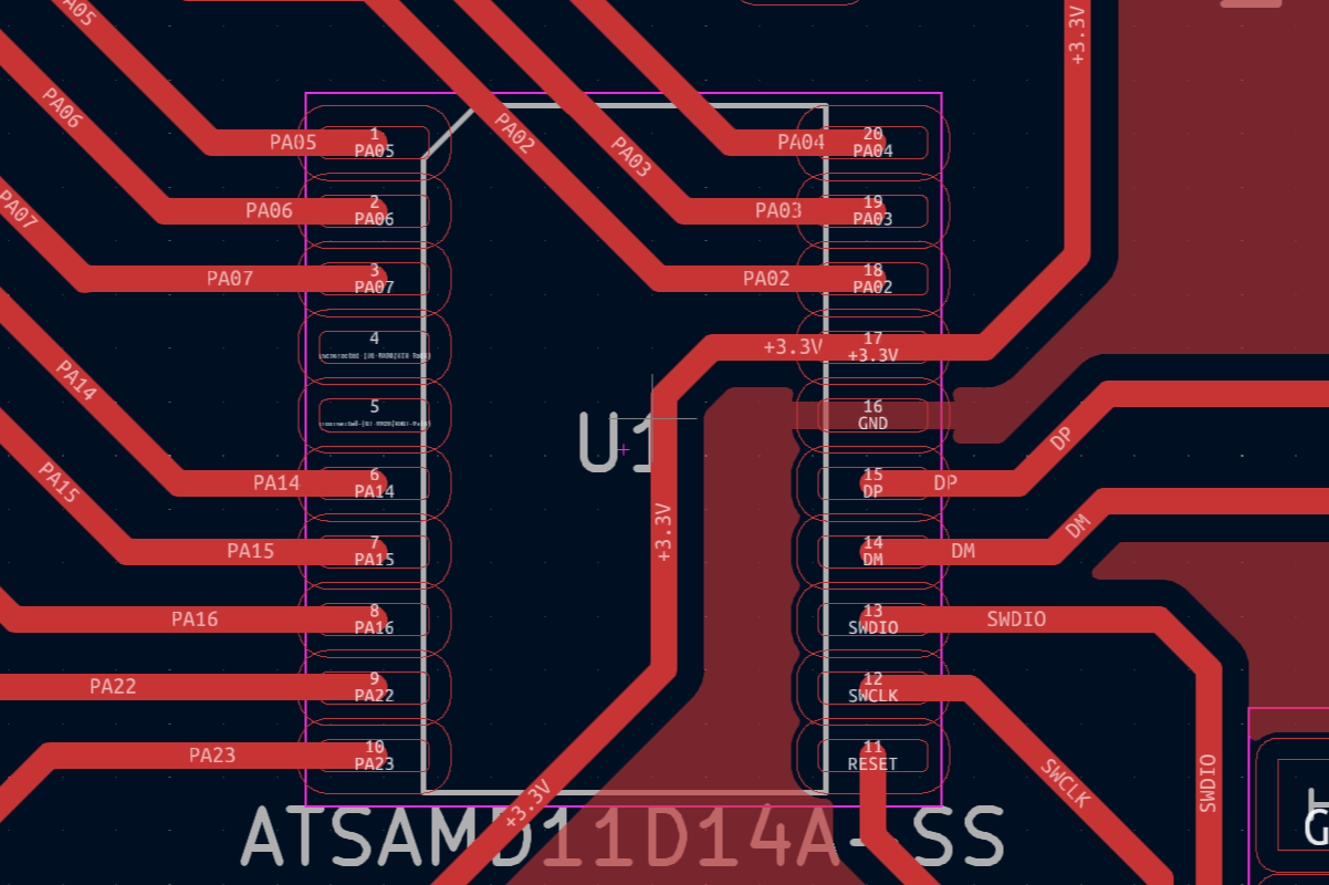
If you look at the generated SVG file, then the place of incorrect generation will look like this
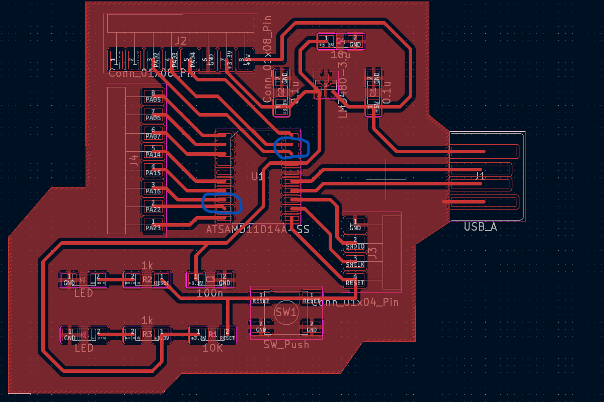
And if you look in PCB Editor, then this place is here
Fixing tracks and getting new boards
The first step is to fix it in KiCad. To do this, I will remove the tracks in places where defects were detected and rebuild them:
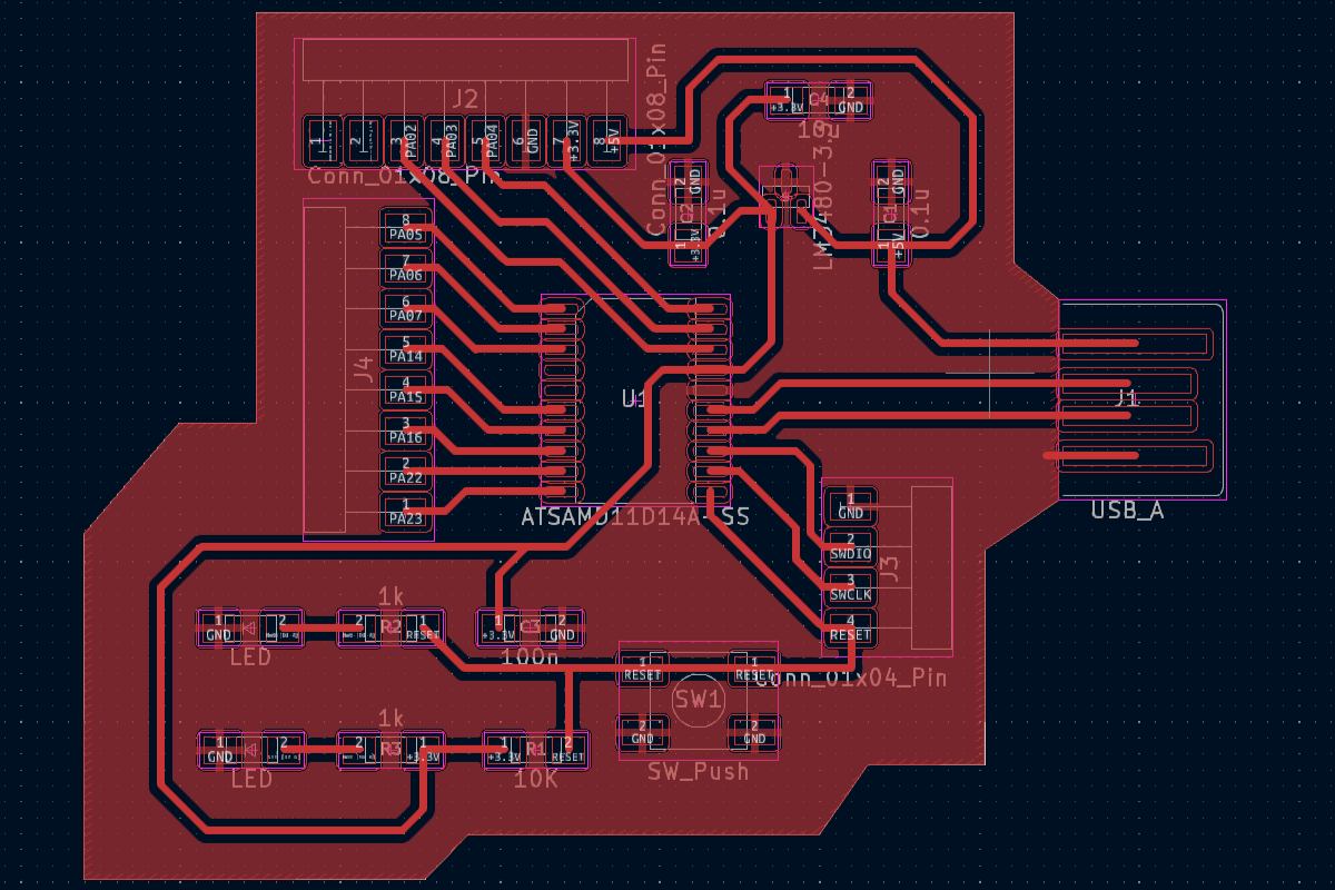
After fixing the tracks in the KiCad Program, I re-export the layer for milling in SVG format.
Then you need to follow the steps described here: G-code for milling tracks
After that, I opened the trajectory of the cutter in the program, I made sure that each necessary place was processed by the cutter:
After I made sure that everything was correct, I re-milled the tracks and cut out the board outline and got the following result:
Soldering components
Solder selection
For solder, I use solder brand kester (24-6337-8834):
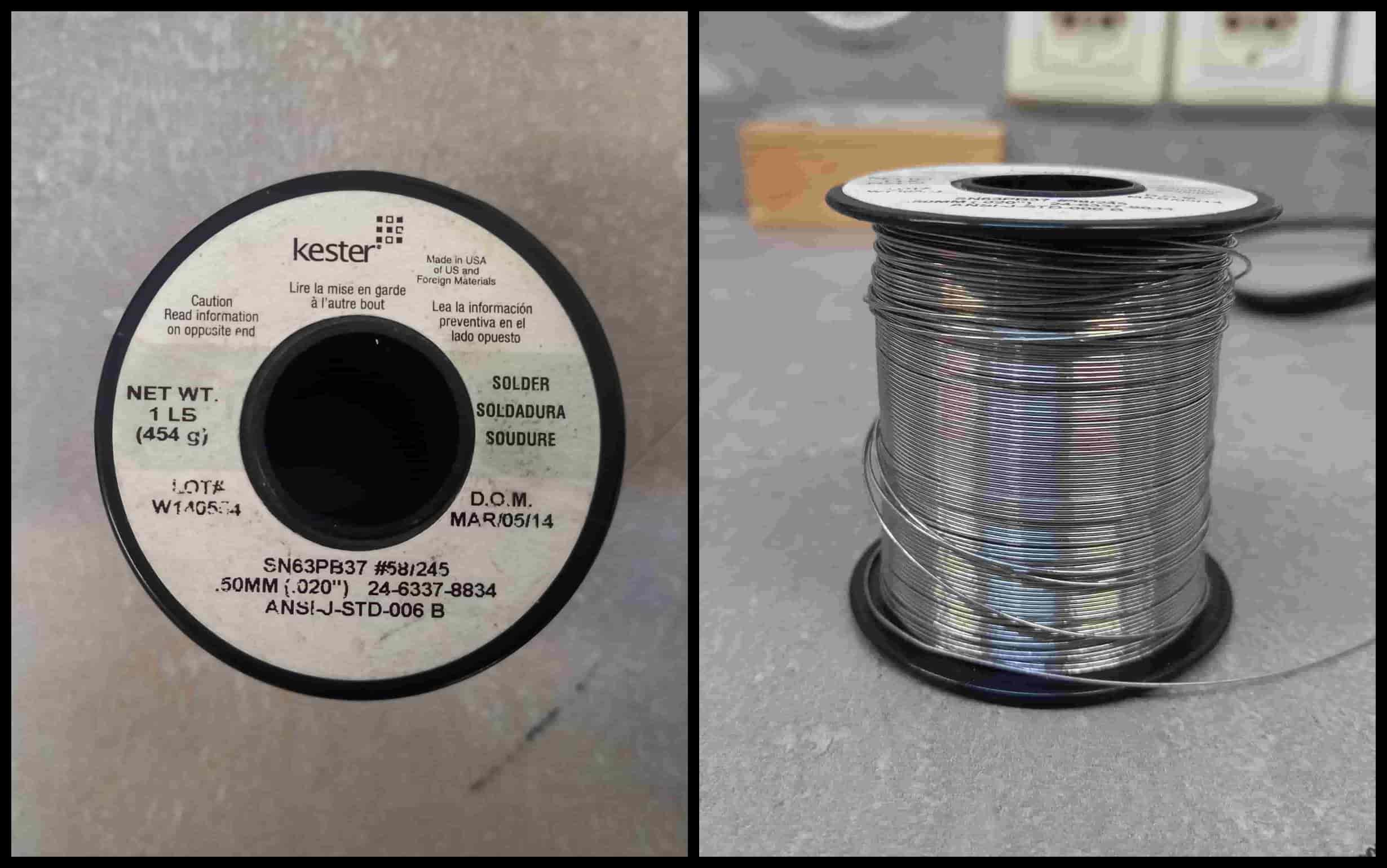
The advantage of using this solder is that there is no need to clean the board with flux. You can read more about this here. I will only note that its melting point is 190°.
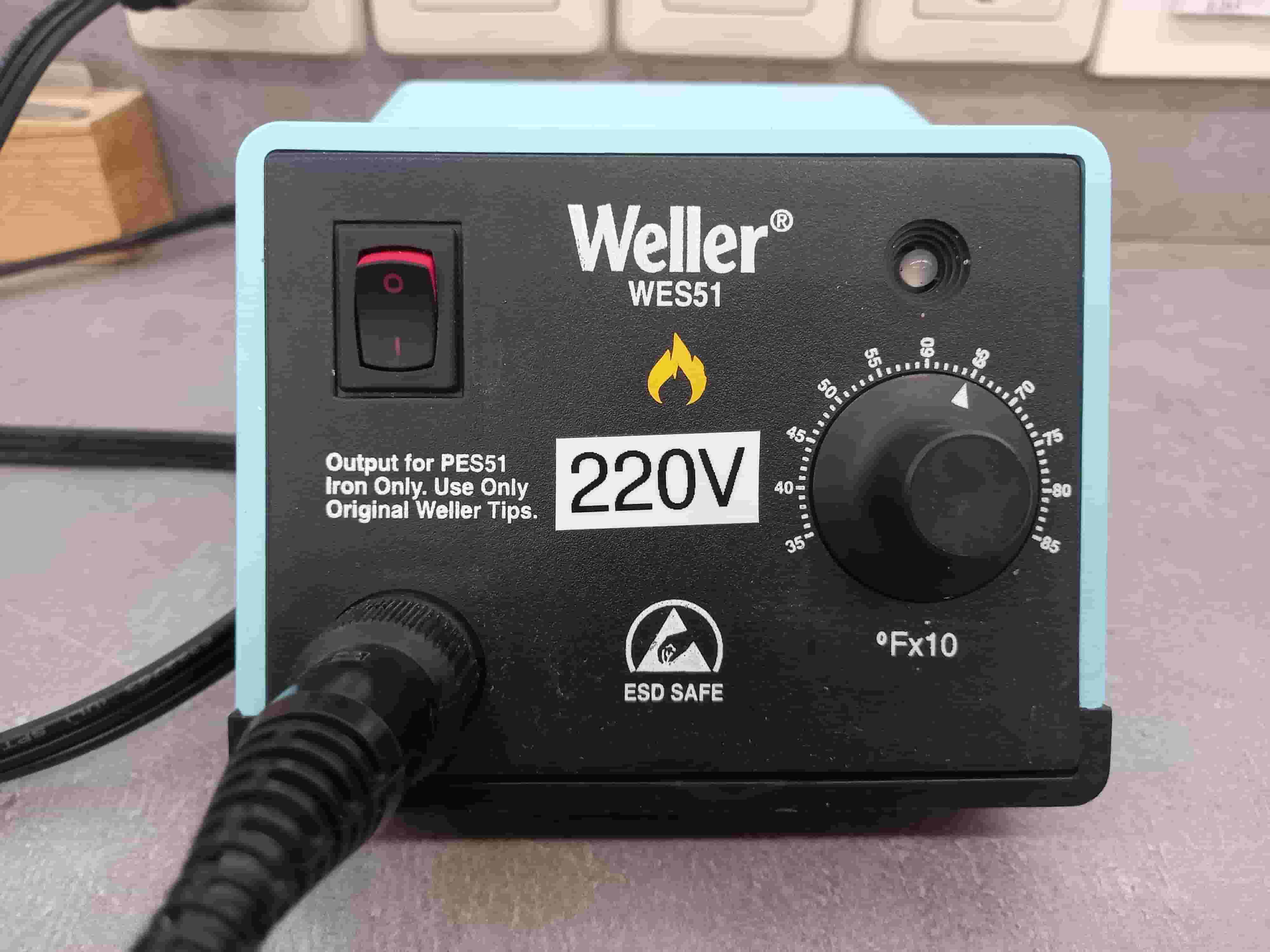
Type of soldering iron
It is advisable to use a temperature-controlled soldering iron. In my case, I set the temperature to 650 degrees Fahrenheit, which is (650 °F -32) * 5/9 = 340 °C.
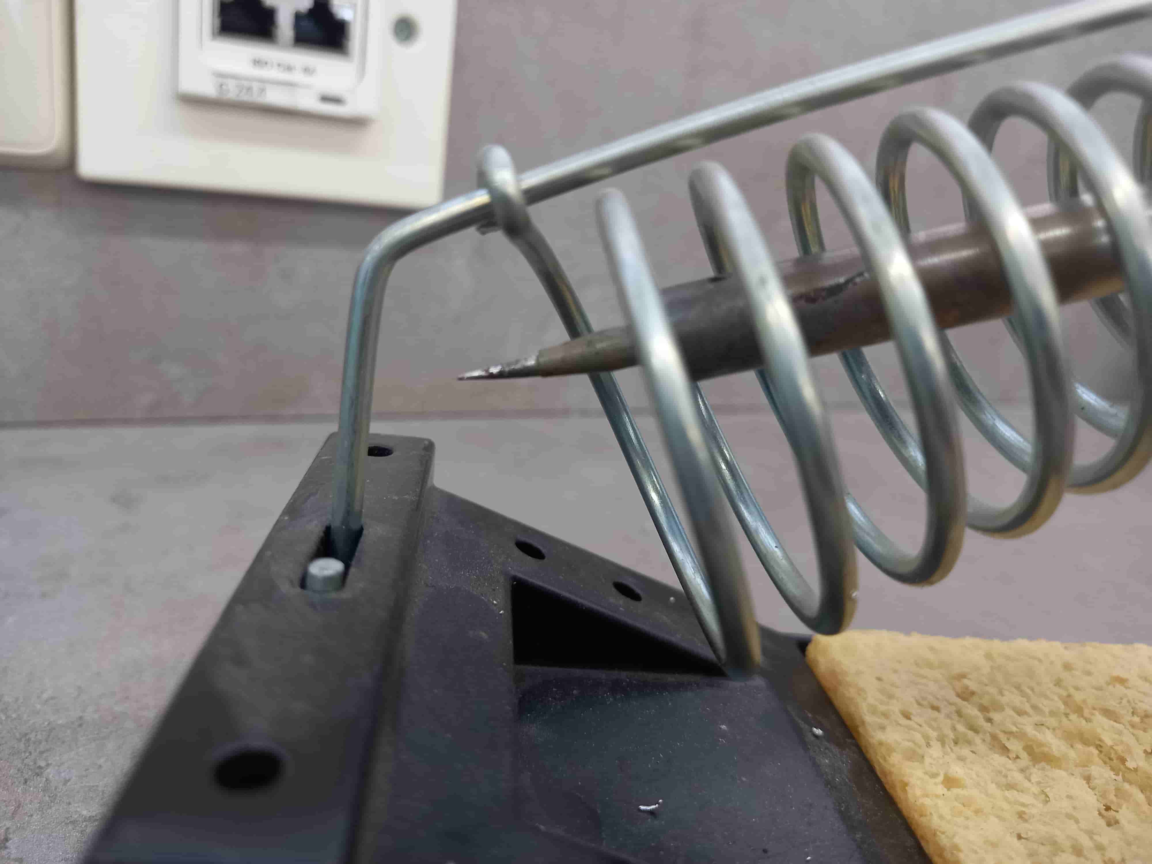
For electronics, it is better to use a soldering iron with a thin tip:
The process of soldering components
-
The first step is to prepare tools and materials:
- Board with installable components
- soldering iron
- Solder
- Tweezers
-
Soldering iron cleaner. It is necessary to wipe the soldering iron tip on a special sponge or cloth to remove solder residue and dirt.
-
Take tweezers and select the component to be soldered onto the board.
-
Bring the soldering iron near the soldering point to heat the pad. This usually takes no more than a few seconds.
-
Solder the component to the board. Apply a small amount of solder to the solder point, press the component against the board with tweezers and allow the solder to cool.
-
Repeat the soldering process for all components on the board.
-
Check soldering quality. Make sure each component is soldered to the board well and securely. This can usually be determined by appearance and with a multimeter.
These were the basic steps I followed during the soldering process.
It must be remembered that the soldering of components requires accuracy and care, so do not rush and follow the process carefully, all work is carried out with a hot tool, and carelessness can lead to skin burns.
Final result
After soldering the components, the board will look like this
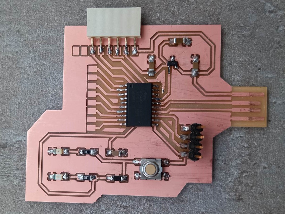
If you insert the board through the USB port into the computer, the LEDs will light up
Bootloader Installation
At this stage, my board is unrecognizable to the computer. To make it recognizable for the computer, you need to load the bootloader into it. A bootloader is a program that is executed when a device is turned on or restarted and is responsible for loading the main program into the device’s memory.
For me, working in the Arduino IDE is comfortable. For this reason, I want to install and download the arduino bootloader which will allow the IDE and Arduino compiler to send programs to the board for execution. Here there is a good guide that explains how everything works.
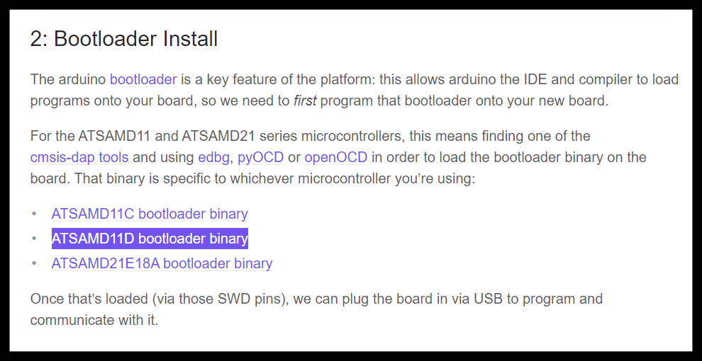
First of all, I will download and install the EDGB software, with which I can program my microcontroller using the tool CMSIS-DAP (debug interface for microcontrollers).
Since my board uses an ATSAMD11D14A-SS microcontroller, I need to download ATSAMD11D bootloader binary.
Now you need to move the downloaded file to the folder with edbg.exe.
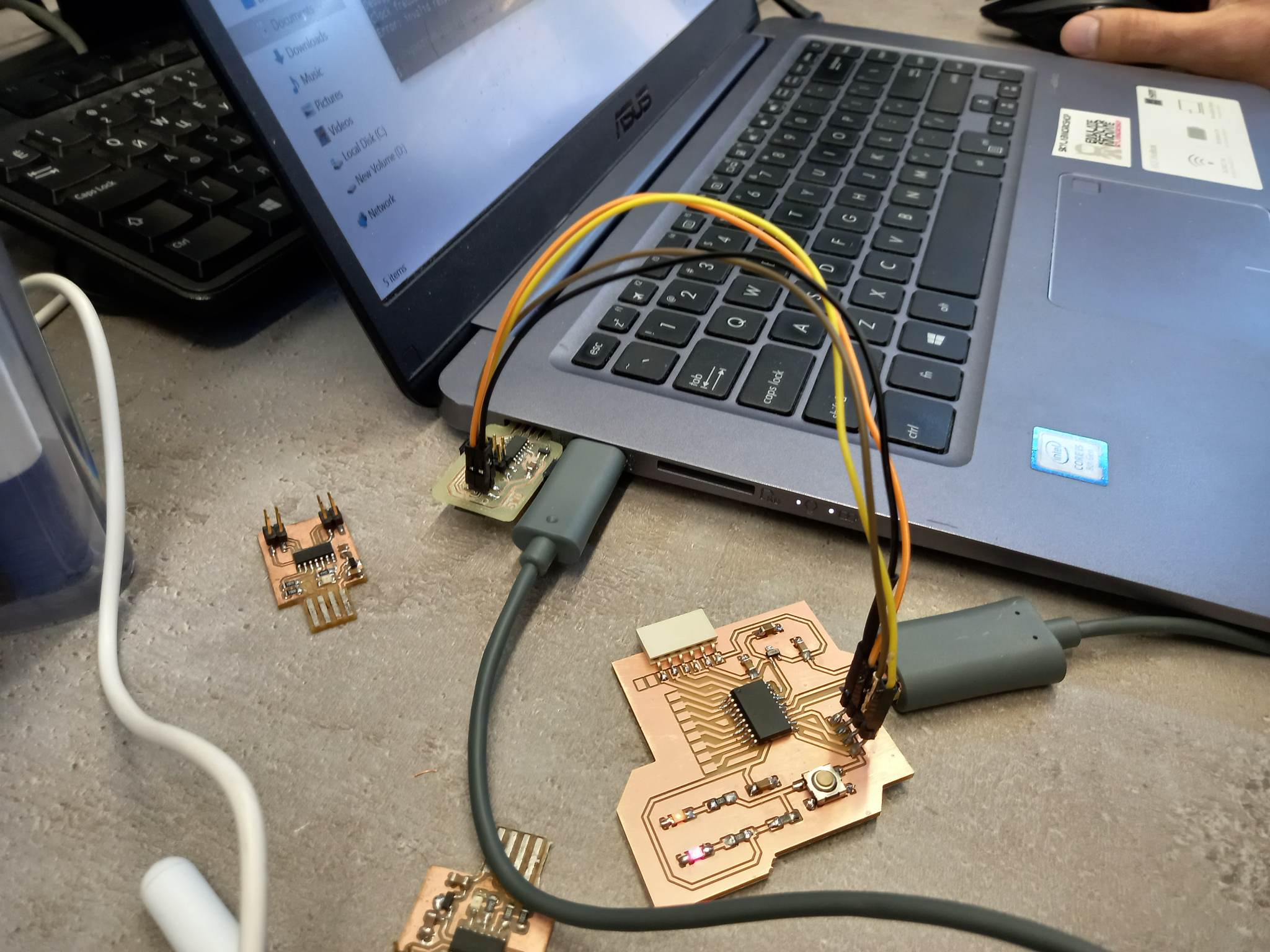
Next, you need to connect the board to the computer via a USB port for power and connect the board’s SWCLK, SWDIO, RESET, and GND pins to the corresponding pins on the programmer.
Then in this folder open the terminal GIT BUSH.
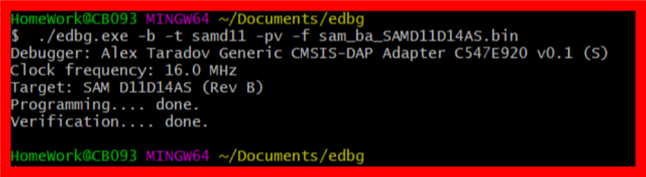
And write the following command:
./edbg.exe -b -t samd11 -pv -f sam_ba_SAMD11D14AS.bin
If the download is successful, the board will already be visible to computers.
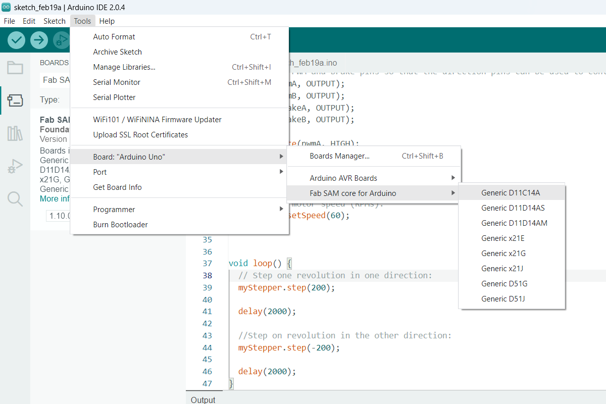
Setting up the Arduino IDE
The second step is to get the Arduino IDE to work with SAMD microcontrollers. There is a detailed instruction about this .
There is a good guide for pinouts
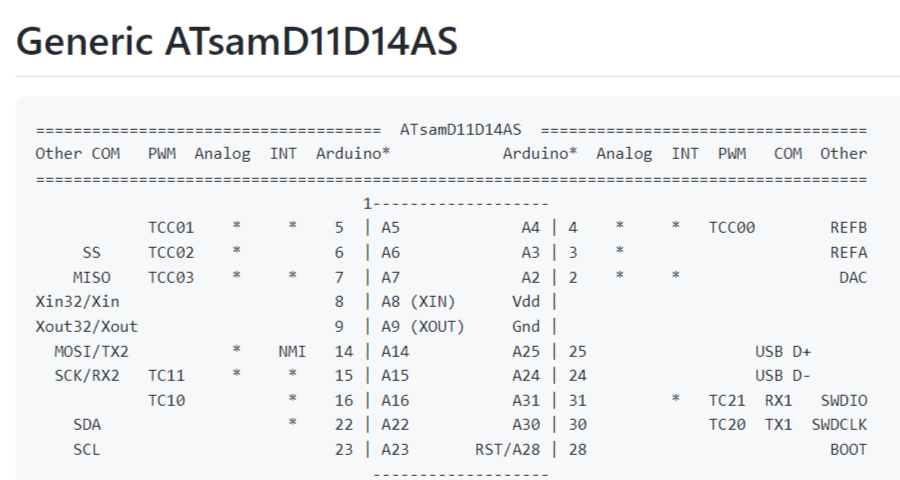
Everything goes well, but when I connect it to the computer via USB, write a program and try to upload it to the microcontroller, I notice that the device is not detected by the computer. And here Babken Chugaszyan comes to my rescue. We opened the documentation of the microcontroller and found that I had mixed up the D+ and D- pins. There are 2 ways to solve this issue:
- Redraw and print the board
- Directly on the board, make a cut of these two tracks and make connections crosswise using a wire.
I chose the second option, and as a result my board got the following look
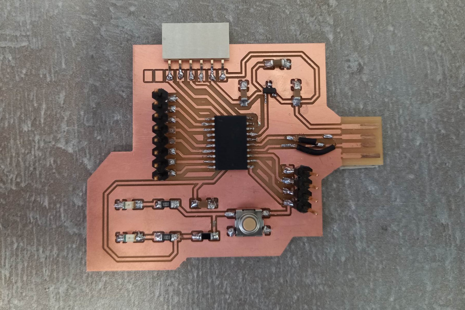
When I turn on the board to the computer via the USB port, two LEDs light up.
Conclusion
This week was very enjoyable for me, as I was able to see the results of my Electronics design project. I connected the soldered board to the computer via USB port and the LEDs lit up successfully. I also uploaded a bootloader to my board, as a result of which it became recognizable for the computer.
However, during the milling process, a problem arose where the cutter could not pass through the gap between the tracks, as its diameter was greater than the distance between them. To solve this issue, I adjusted the distance between the tracks, and the second attempt was successful.
As for the soldering, the most challenging part was soldering the microcontroller, since its legs were significantly smaller than the legs of other components.
Files
SVG files for carving and cutting the board