3. Computer controlled cutting
Group assignment
Details of our group work can be found here.
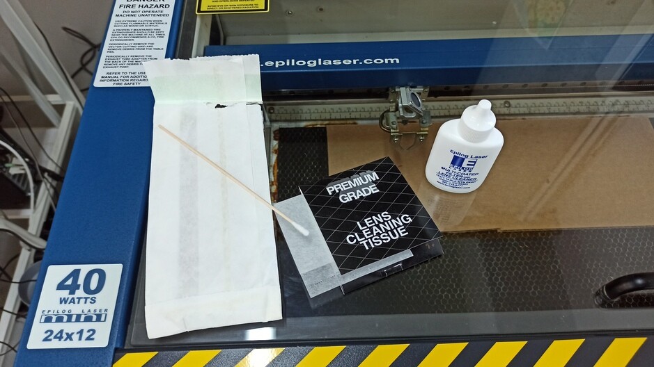
As part of a group assignment, we looked at working with a Epilog mini 24 40W laser machine.
Safety precautions
Since the laser itself can lead to the ignition of the material, it is important to observe safety precautions, namely - Application of the Air Assist system in material cutting mode. - Never use the laser system unattended. - Keep a properly maintained and tested fire extinguisher handy.
Laser focusing
There are two ways to determine the position of the laser focus: - manually - automatically
Laser Maintenance
It is important to keep the laser machine clean, namely: - checking that the smoke extractor has fresh filters and is working properly - it is necessary to clean the lens and mirrors every week by the recommended method described in the manual.
Measured the thickness of the cut
To measure the cut, we cut out 11 rectangles 10mm wide. When measuring 11 rectangles at once, the cut thickness turned out to be (110 - 108.52) / 11 = 0.135 mm. And when measuring one rectangle, it turned out 10 - 9.860 = 0.140 mm.
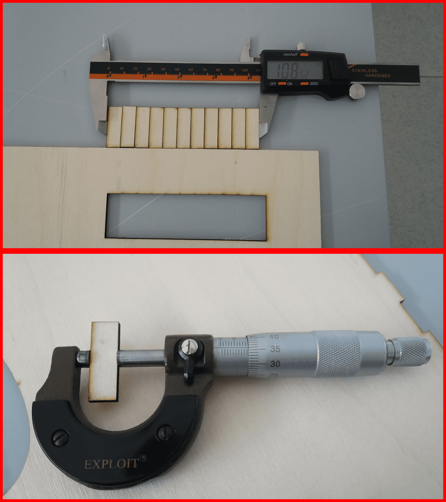
The two results are approximately equal.
Engraving and cutting
We made probes for engraving and cutting for three different materials: for cardboard, plywood and organic glass
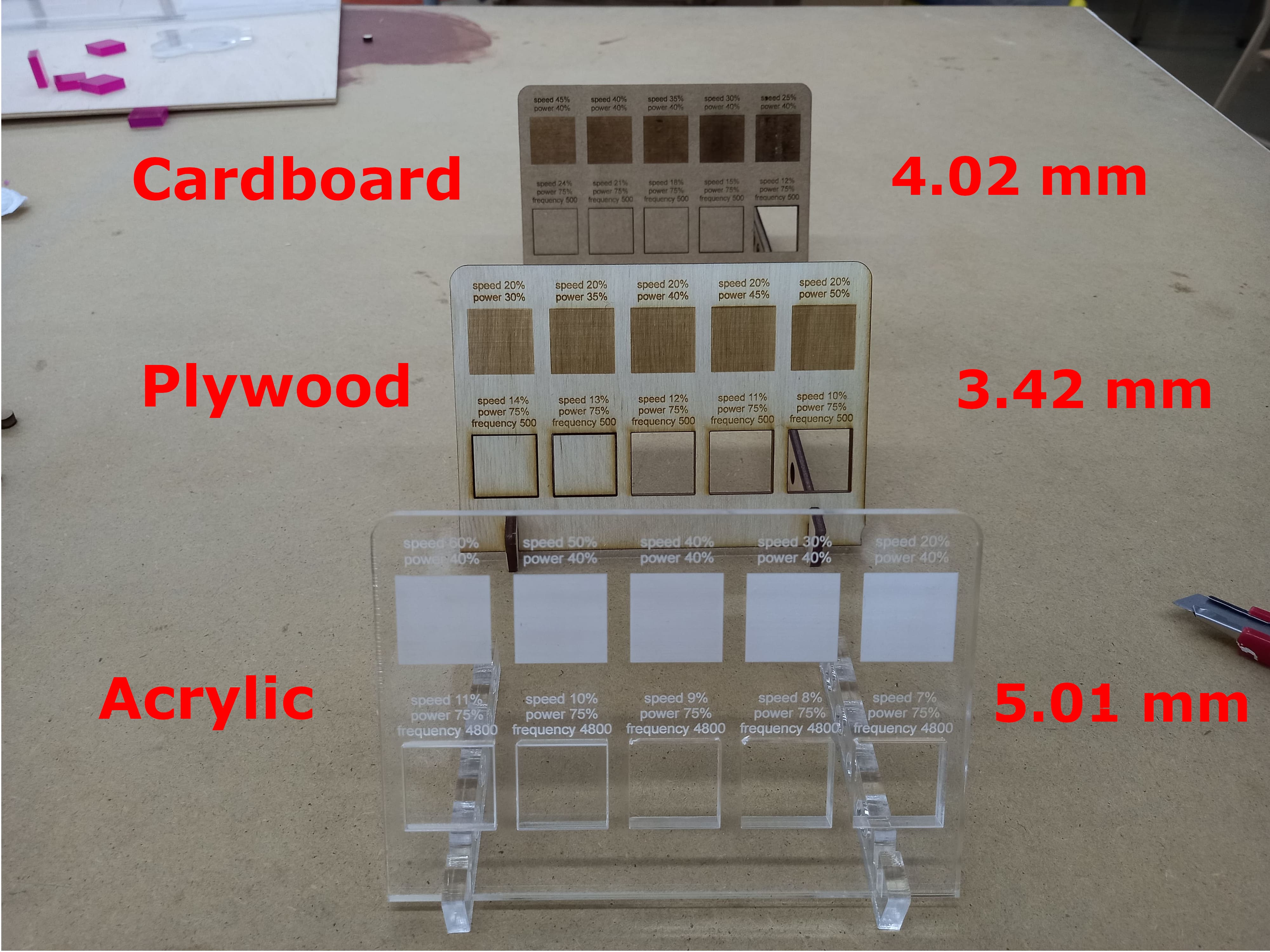
The values are different from the standard data settings in the manual, this may be due to laser wear.
Working with vinyl cutter
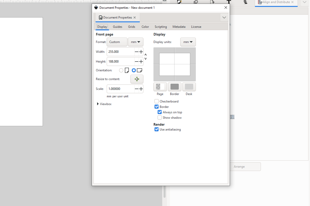
Cutting area
I measured 281mm by 250mm rectangular paper and placed it under the vinyl cutter. The machine calculated and gave me a working area of 255mm by 188mm.
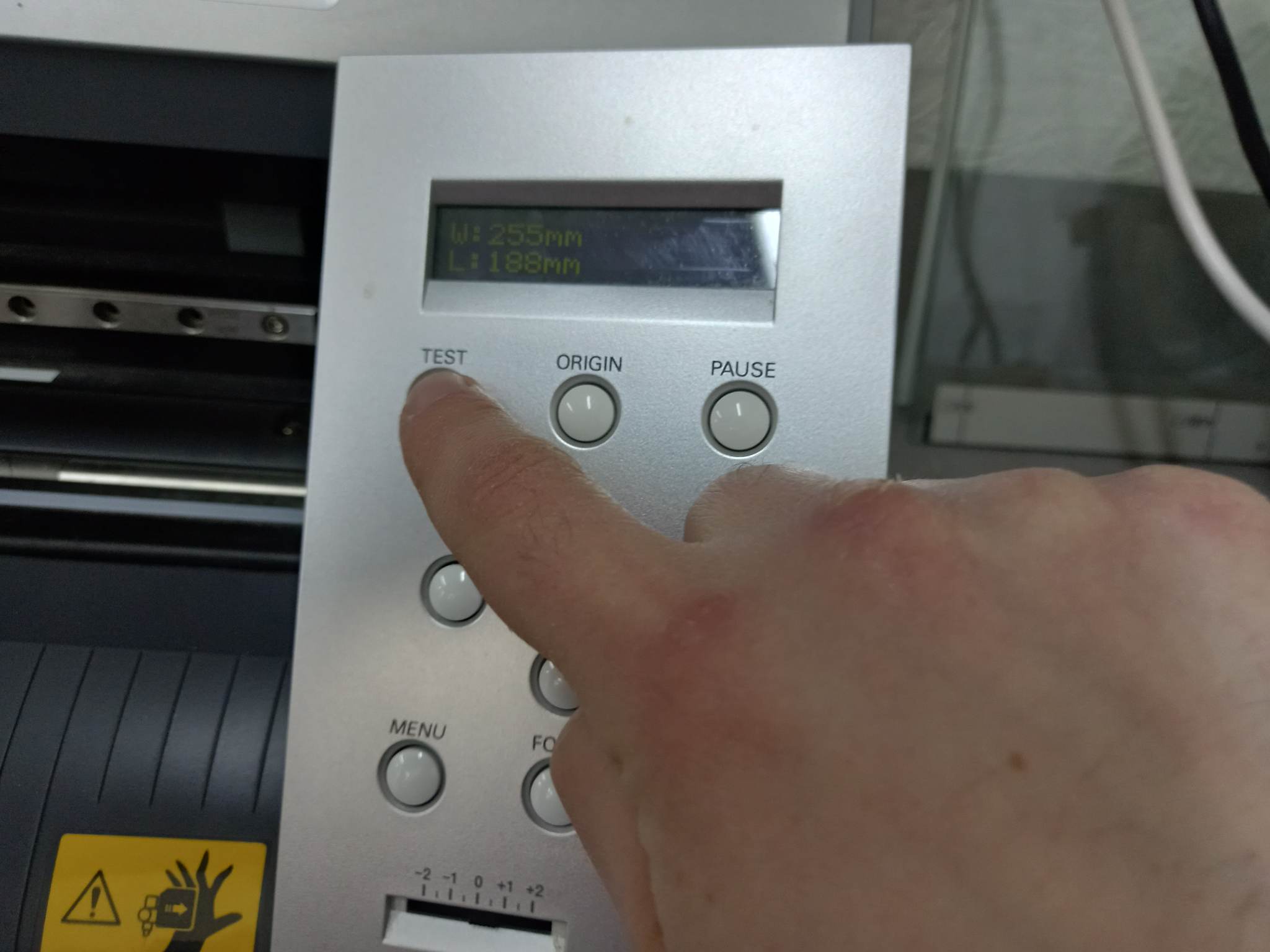
If you need a specific working area, then you need to take a piece of large sizes
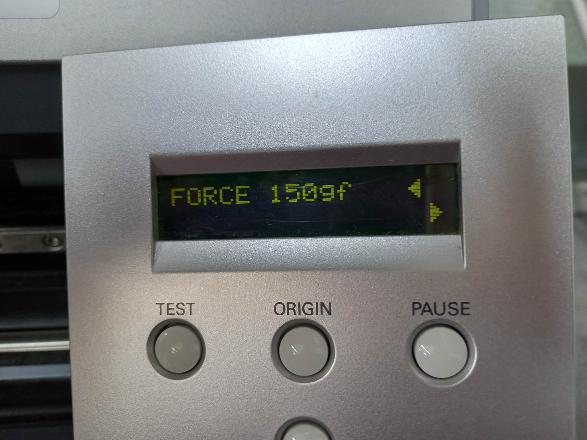
Force test
I performed test cuts with different force settings to check the spectrum of results and find the perfect force setting for this specific vinyl.
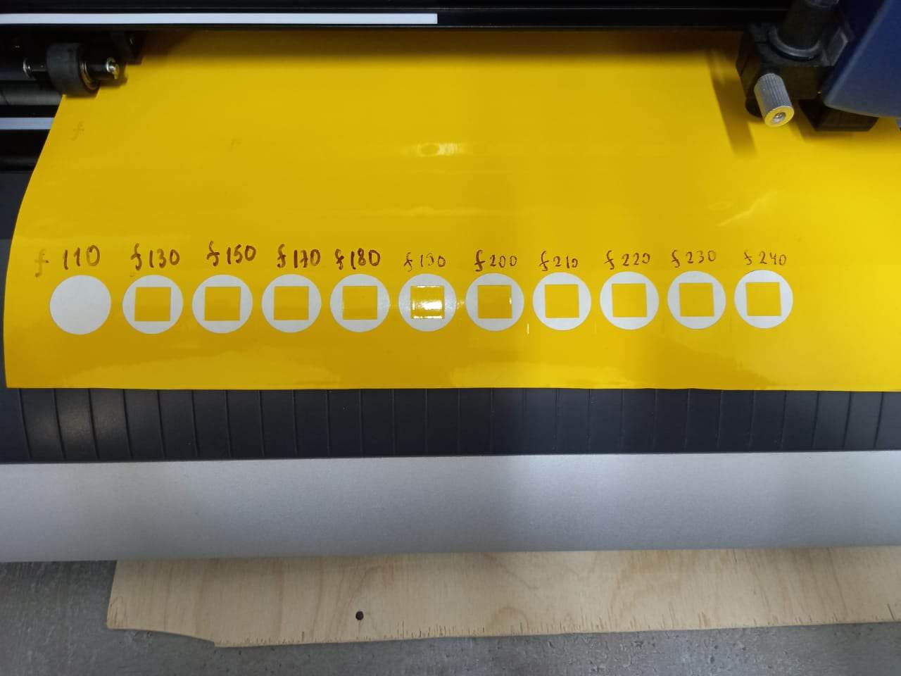
The ideal setting I found was 150gf.
Drawing for cutting
Our vinyl cutter works through the Inkscape program. In this program, I will specify the page sizes.
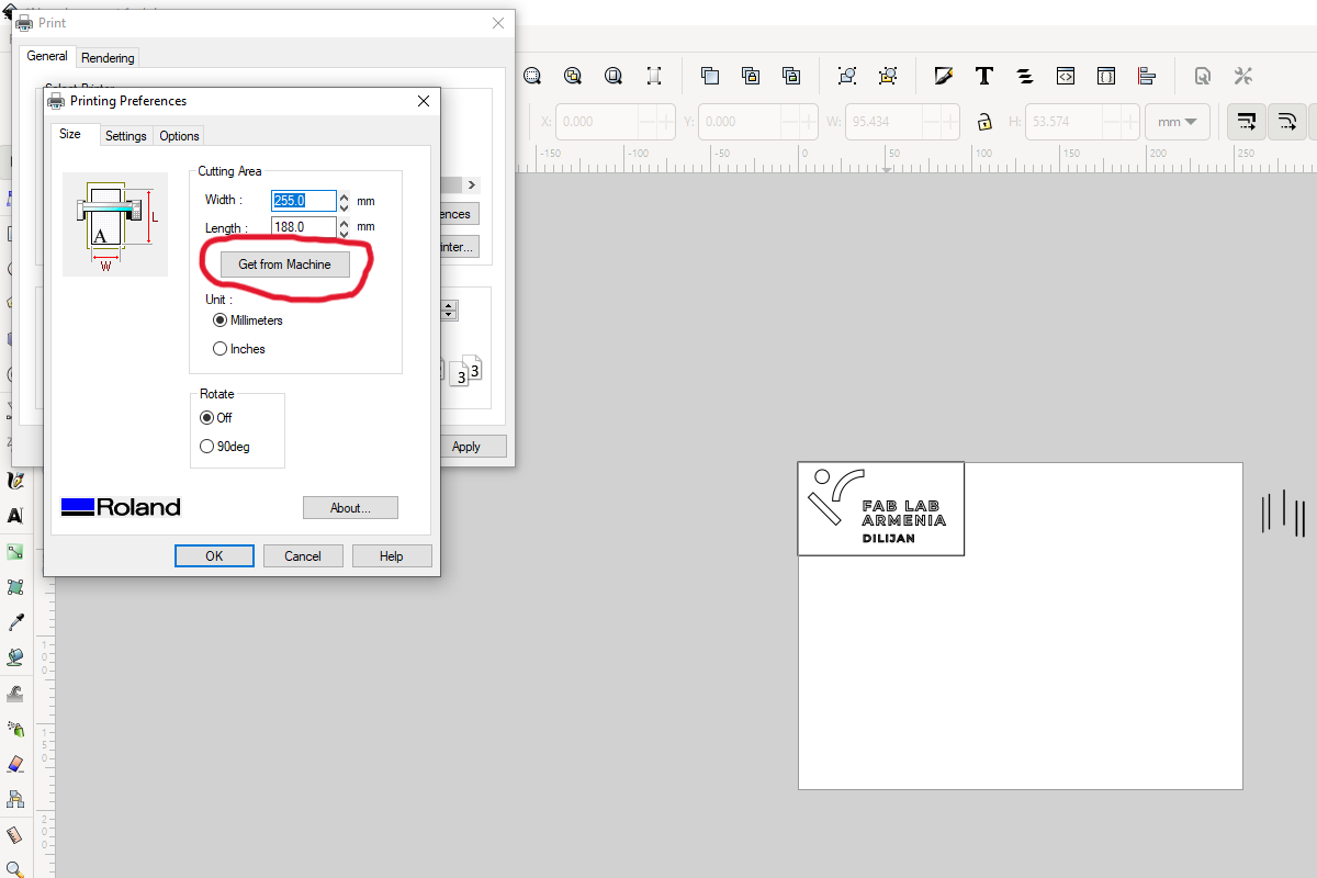
I found the logo of our FAB LAB Armenia Dilijan and decided to print it out. Positioned in the place where I want to cut.
![]()
To print
Then in the print settings in the place Cutting Area I clicked on the button Get from Machine and got the parameters of the piece.
Then I pressed print.
Cutting result
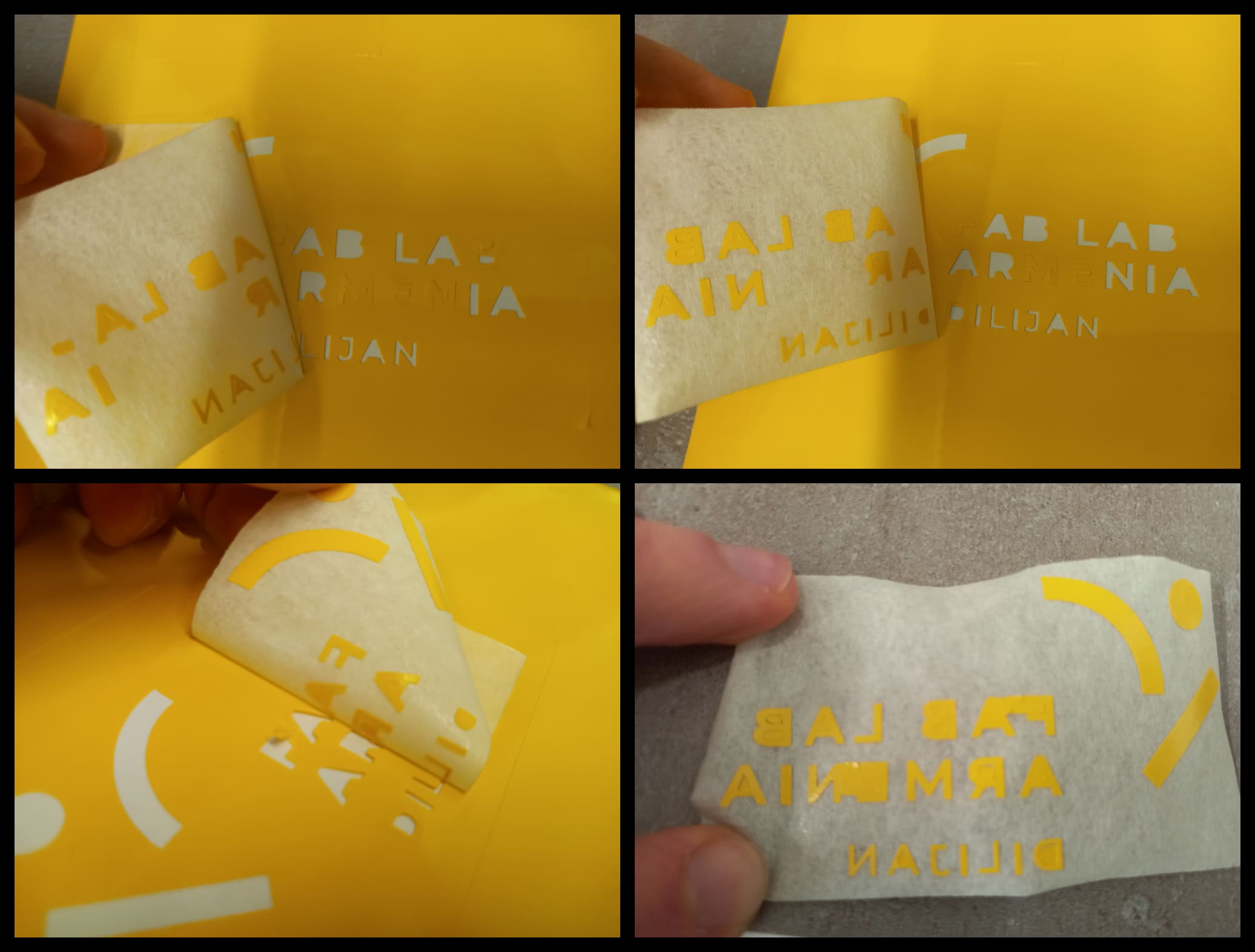
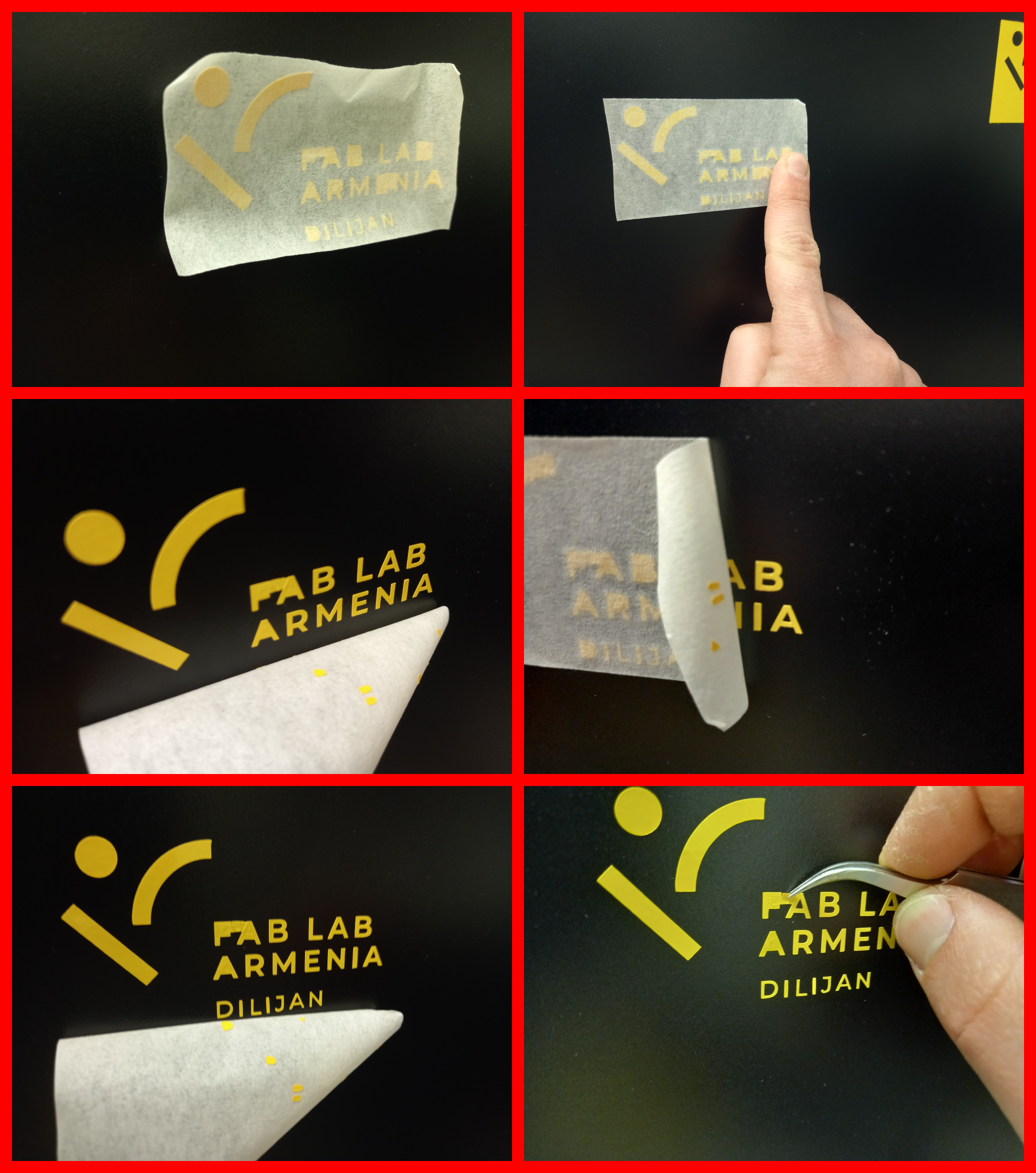
Since the vinyl has a yellow color, it is very difficult to capture the resulting outcome on camera. I took several photos on my phone to showcase the cutting result, but almost nothing was visible in them. However, by using the micro photography mode, I was able to capture the textual part and the shapes of the logo more clearly and in greater detail.

Cutout separation
I decided to use the inner part of the cutout. Although I performed a test cut, there were some areas where the small text did not cut well. As a result, the outer part did not separate easily. To solve this problem, I decided to use masking tape.
I attached tape to the surface, which covered the entire logo. The use of adhesive tape helps to maintain the distance between the letters. If they are removed individually with tweezers and fixed to the surface, it will be very difficult to achieve the desired result.
If there was only one line of text, the best solution would be to attach tape to half the height of the text. This would allow the use of tweezers in case the text does not detach well from the cutout. It would provide greater precision and control when separating the text from the cutout.
I wasn’t able to detach the desired part from the cutout right away, but I used a method of attaching and detaching the tape, as well as applying pressure to the areas where the letters and shapes of the logo were located. Thanks to this, I was able to achieve that the entire desired part stuck to the tape.
Using cutout
Let’s look at what the use of a rectangle to emphasize our drawing can give us.
Essentially, it may happen that we only need to use the inner part. However, if we want to create multiple cutouts and use them later, the use of an additional rectangle (or another contour) will help us divide them into logical sections.
Another important advantage is the ability to obtain two usable units from a single cutout. In this example, I was unable to use the outer contour since it was a bit torn between letters F and A possible reasons are: that part was not cut properly or/and I was peeling it too fast and torn it apart. However, if I had separated the outer contour first and then the inner one, I could have ended up with two units that could have been used.
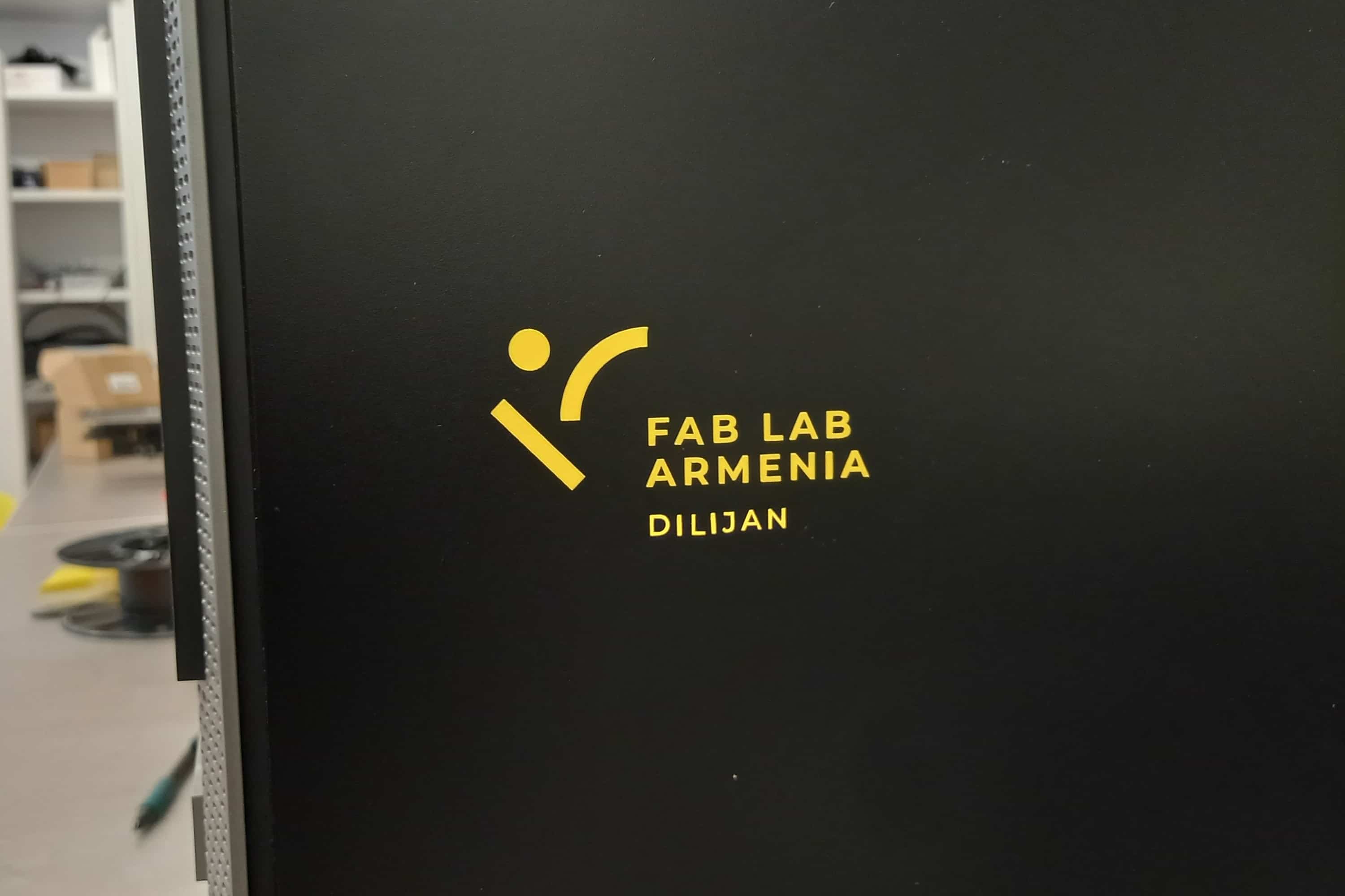
Okay, let’s start gluing. Cleaning the surface before gluing is very important to ensure good adhesion of the material. In my case, I use alcohol and a tissue to clean the surface.
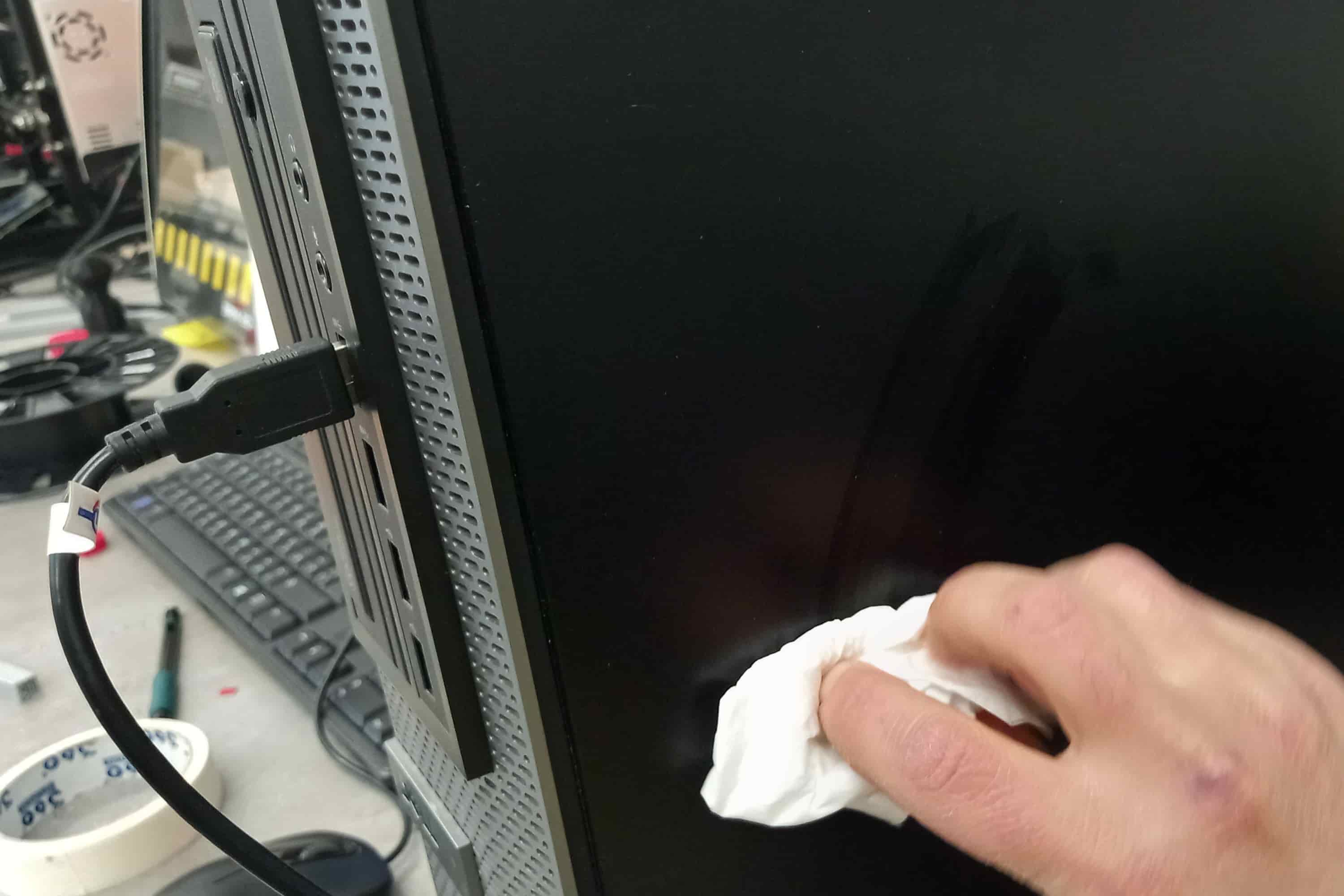
I then attach the paper tape to the cleaned surface by applying pressure with my fingers where the vinyl is. Repeated attempts help to achieve a good adhesion of the vinyl to the surface, so that when removing the tape, the desired vinyl parts remain in place, and unnecessary parts can be removed with the help of tweezers.
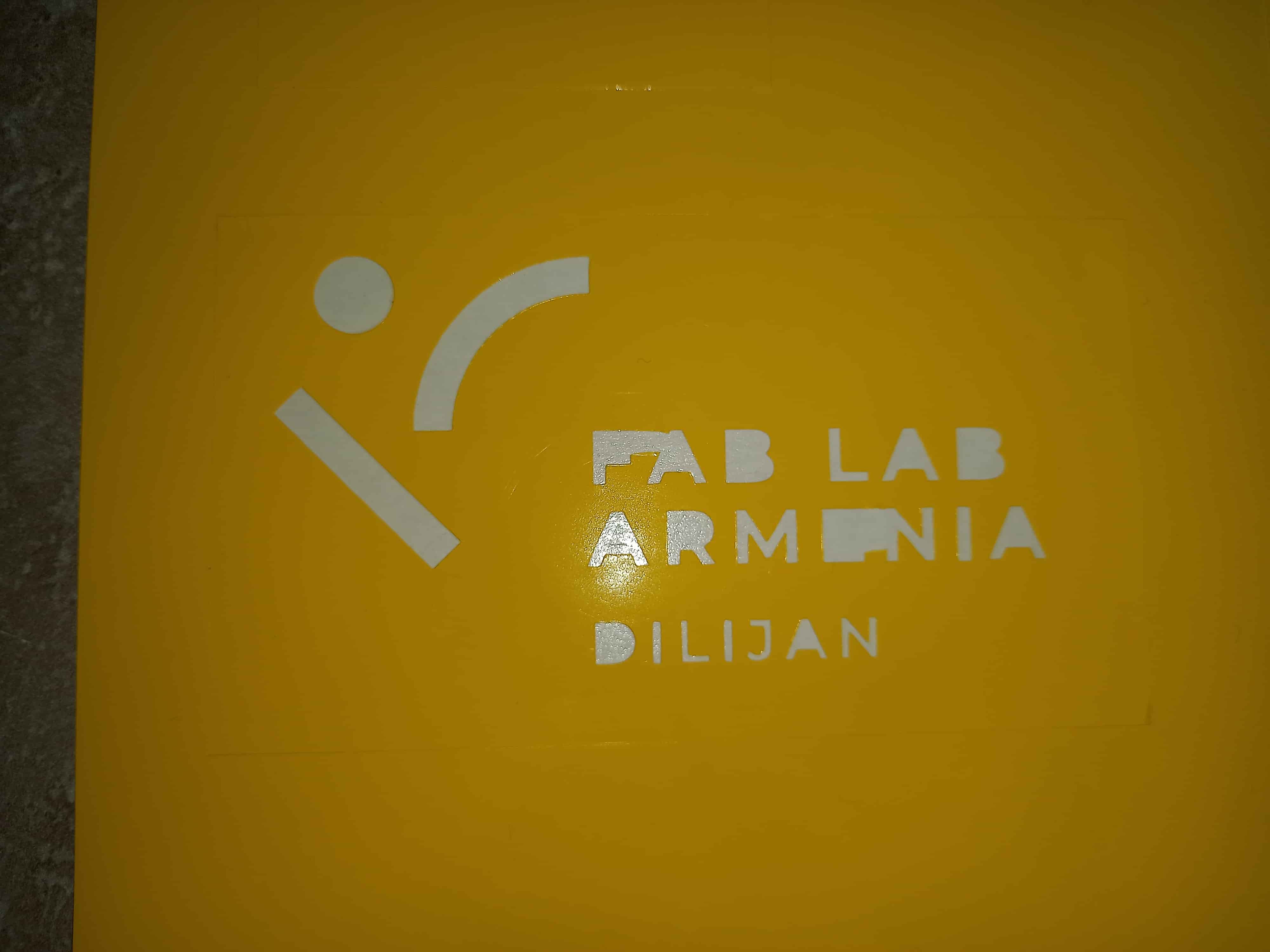
This is what the final result looks like:
I made another cut to have a successful outer contour here’s the result:
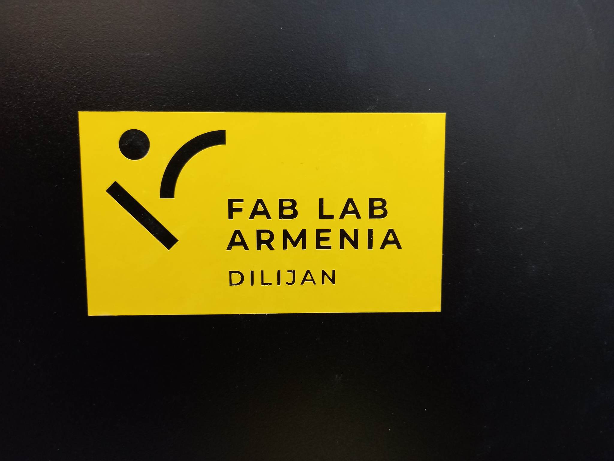
Vinyl yellow looks very good in black, but the process is a bit unpleasant for the eye.
Working with a laser
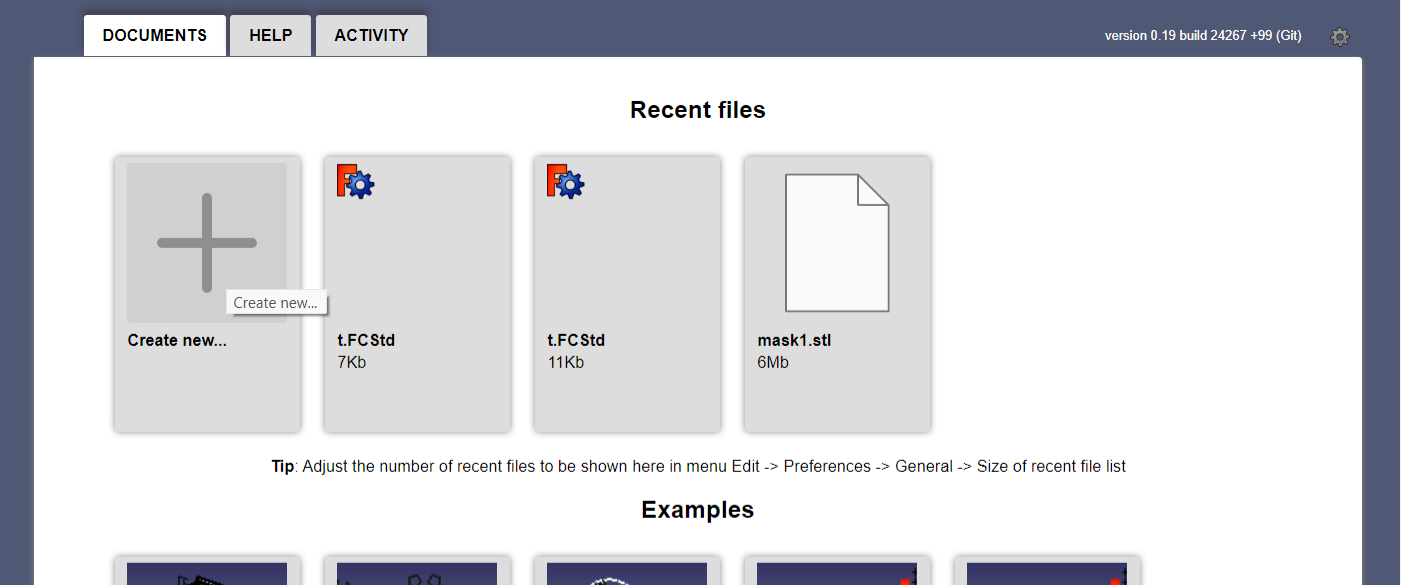
Drawing on FreeCad
- The first step is to create a new project
- The second step is to create variables. In order to do that we should change the workbench to Spreadsheet
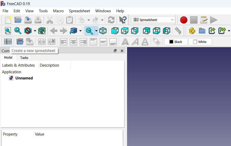
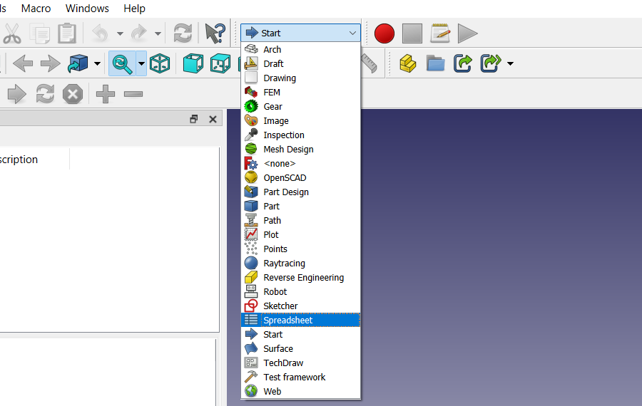 Then create a new spreadsheet by clicking the spreadsheet icon on the left side of the tools
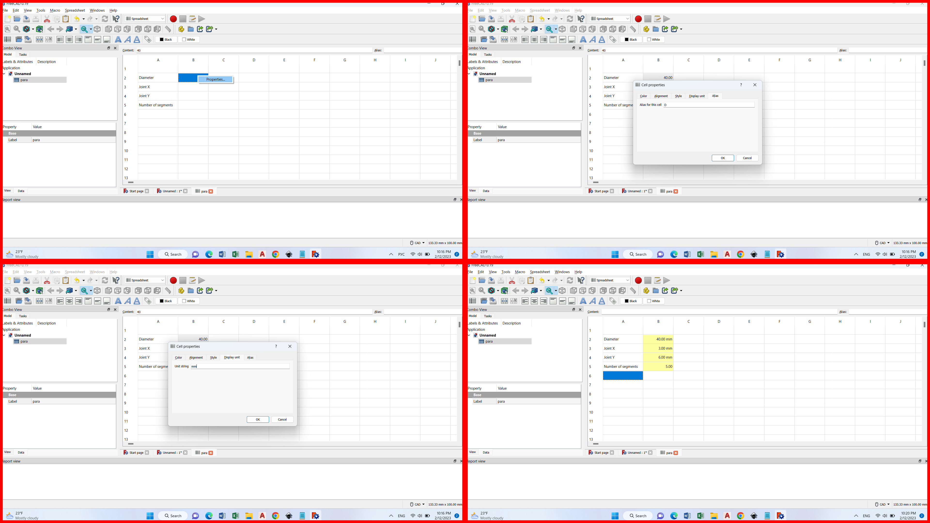
In my case, the parameters are the diameter of the constructive circle, Joint dimension along the X axis, Joint dimention along the Y axis, and the number of segments.
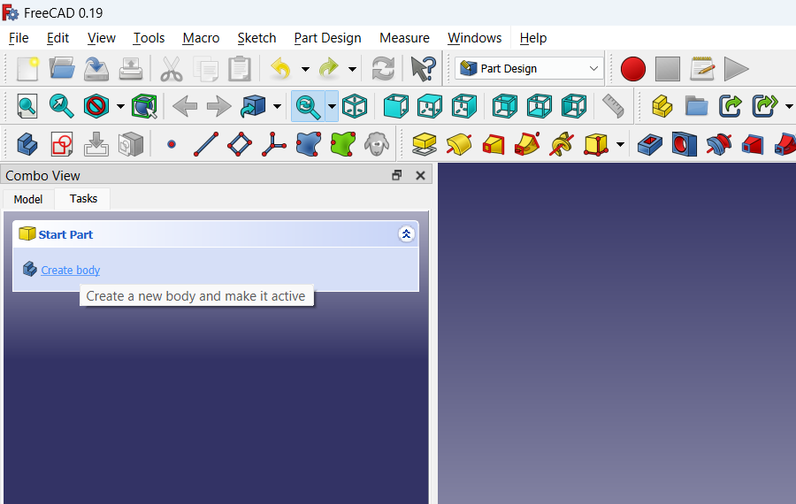
- The third step is to go to the Part Design workbench and create a body
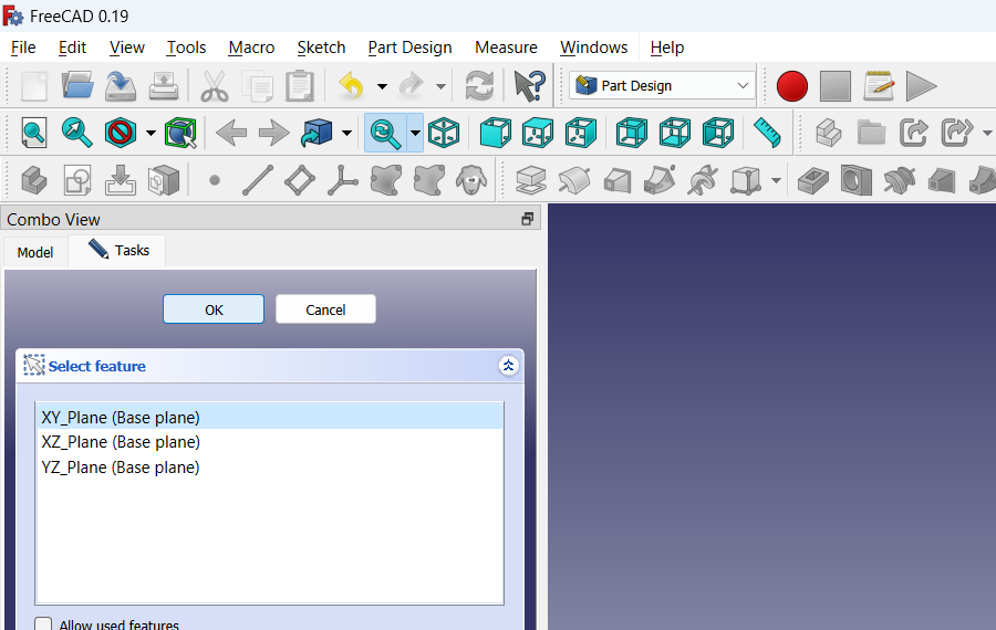
- The fourth step create Sketch and select plane XY
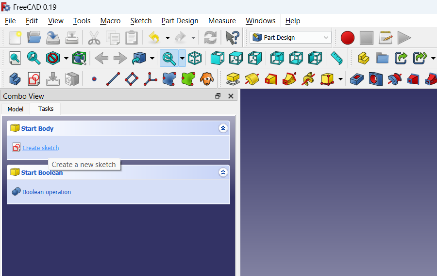
- Create a circle at the center of coordinates
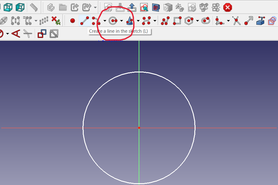
- Make the circle a construction circle by selecting the circle and hitting the highlighted tool
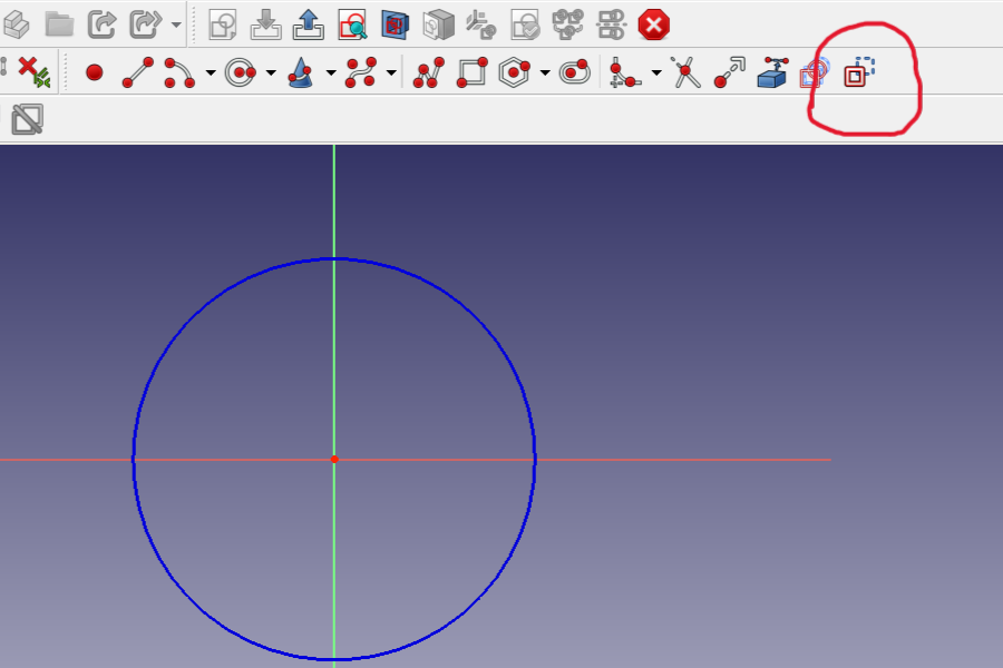
and it will change its color to blue and this circle will act as construction shape and will not appear in the actual model. Construction shapes are meant to be used to create other things referring to them
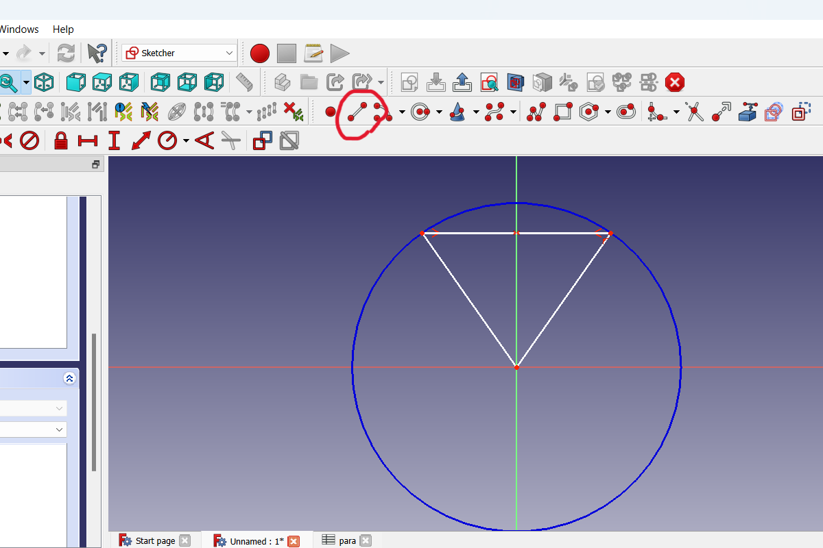
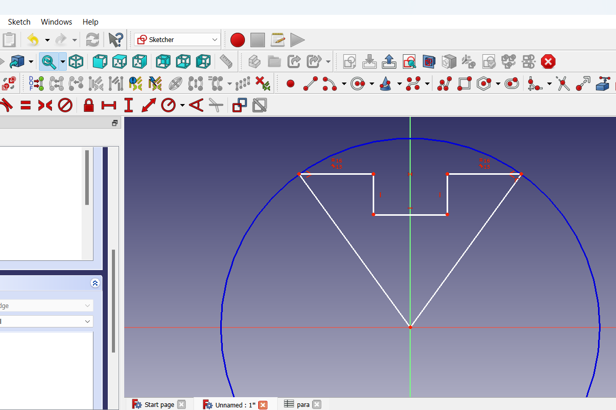
- now add 2 lines that start from the center of the circle and end on the outer edge of the circle.
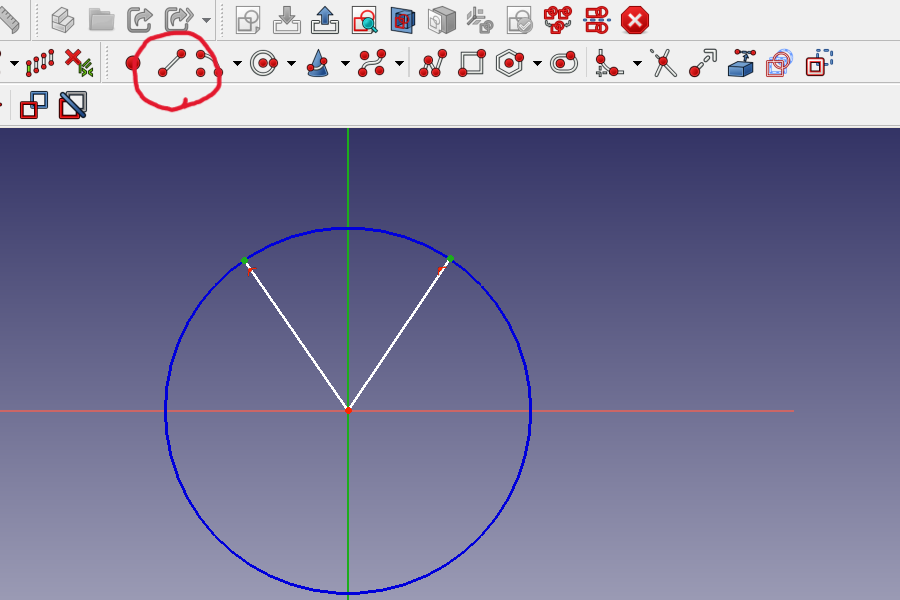
These lines are still free to move
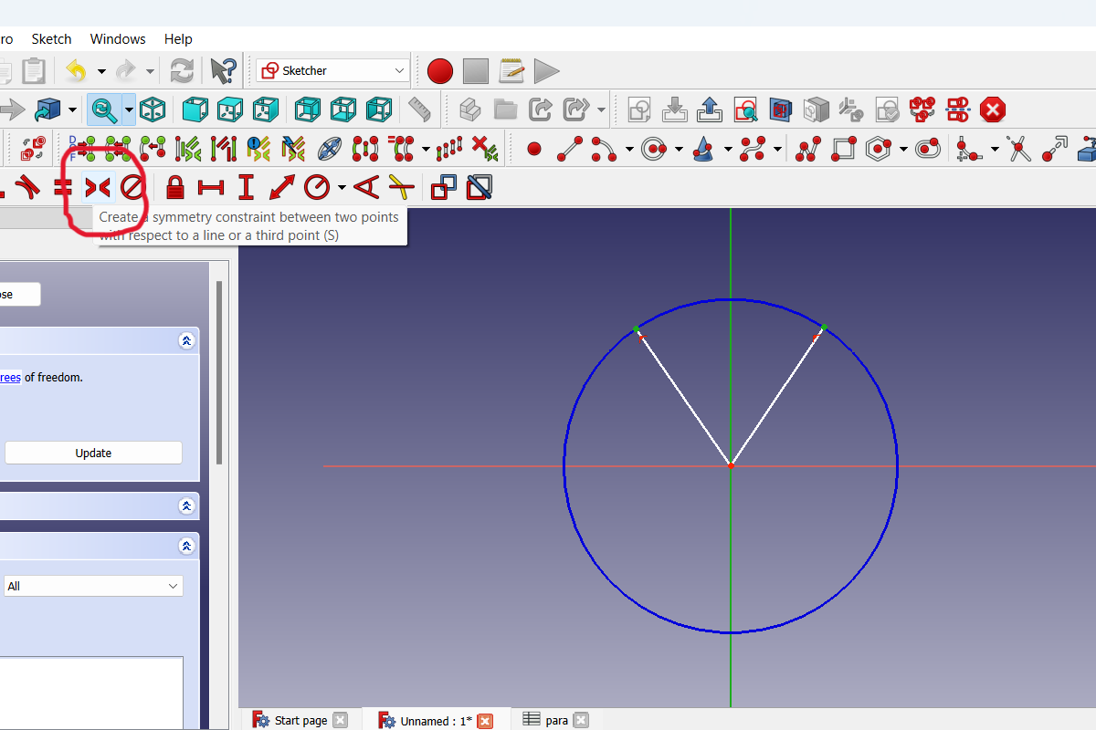
- Now you need to make these lines symmetrical to each other in relation to the Y axis. To do this, select the end points of these two lines which are on the circle and the Y axis then you need to click the symmetry constraint
In my case, an error is thrown.
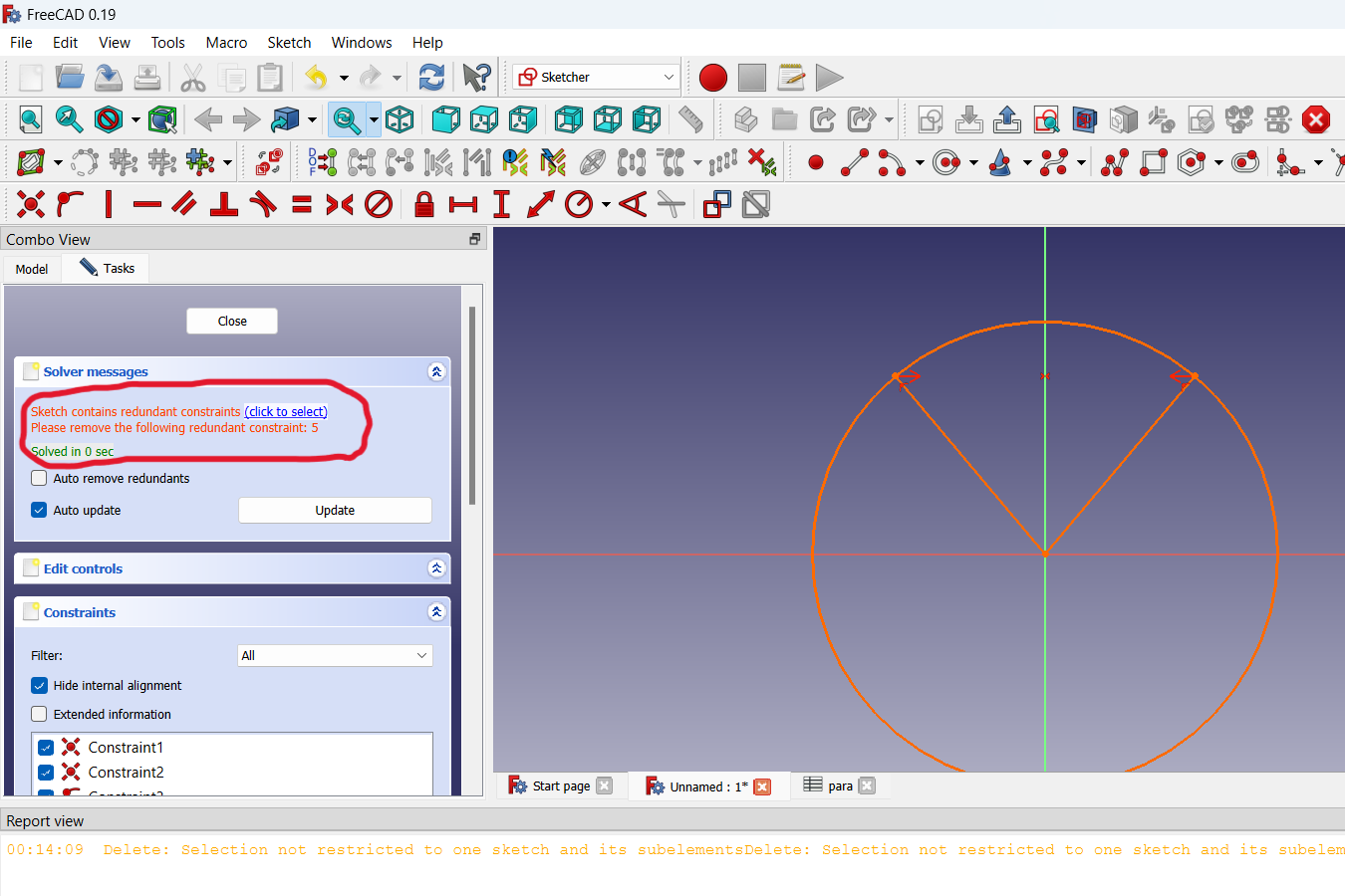
To fix this error, I will remove the unnecessary dependency and in the end everything will work out.
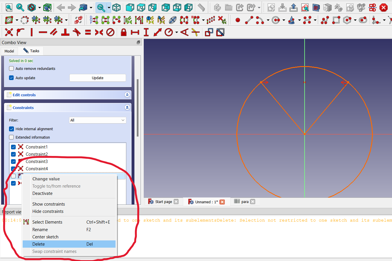 This happens when you create redundant constraints

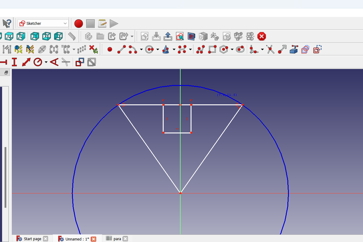
- Then connect these two lines.
- Add a joint
- Then you need to remove the extra lines.
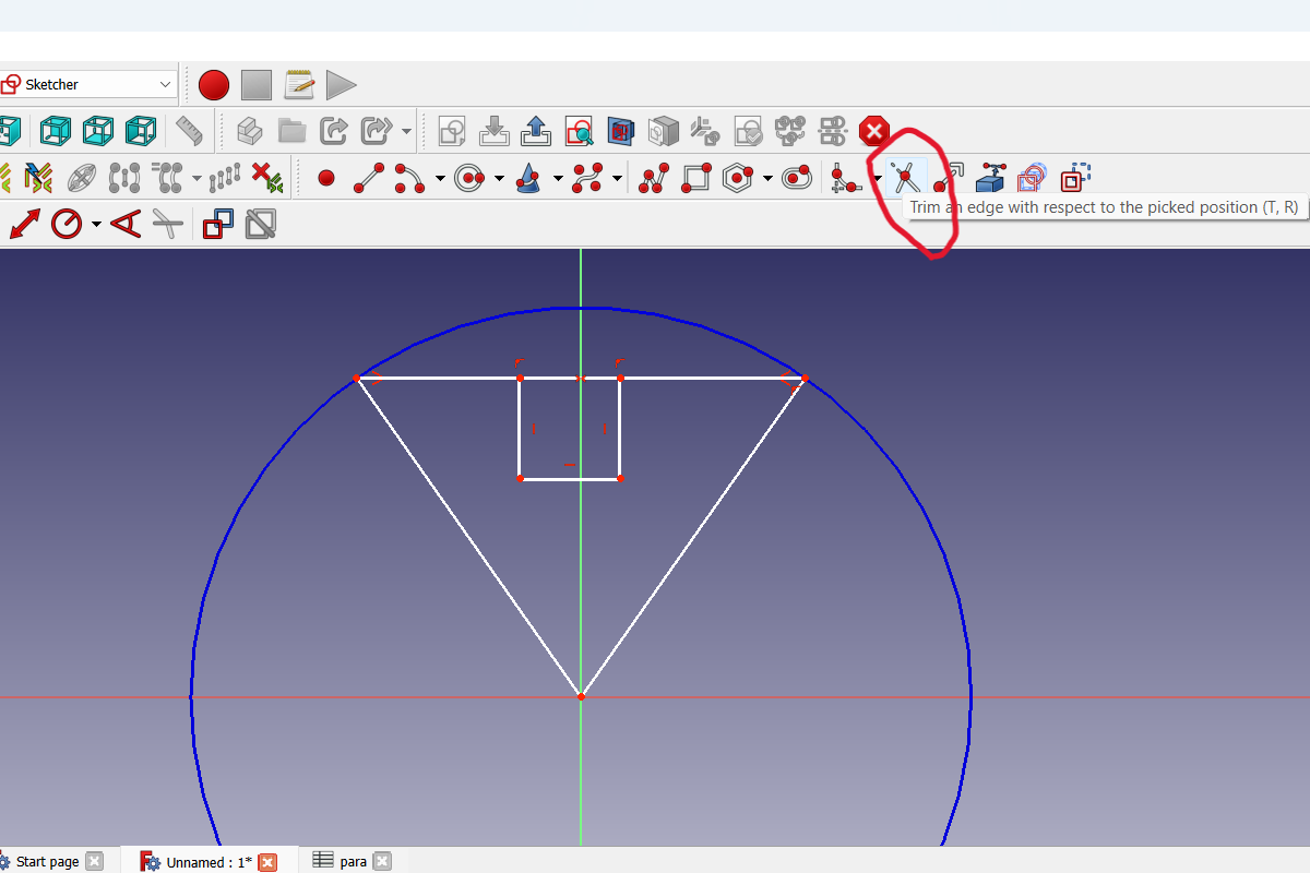
As a result, it we get more moving poins that need to be constrained
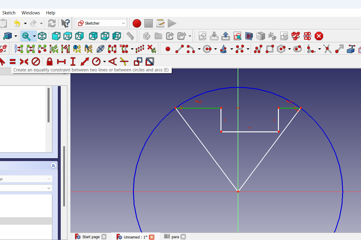
- WE need to fix the parameters of the joint as well, from the endpoints of the lines on the circle to the joint must be equal.
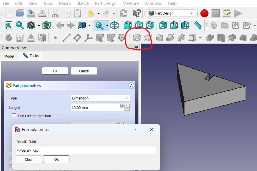
- At this stage, you can already add the parameters that we created earlier.
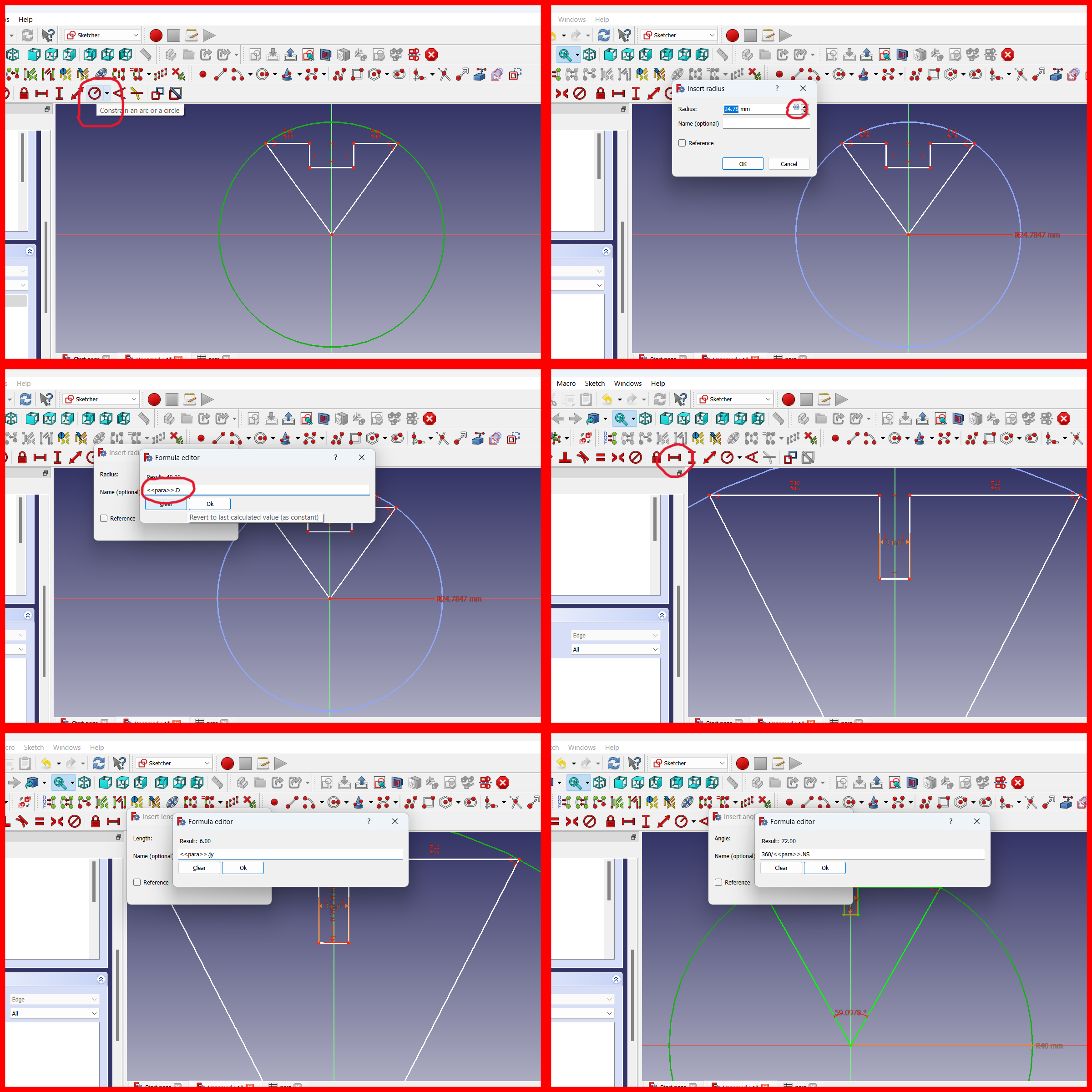
As a result, the model is completely green, which means that all its lines are fully constrained.
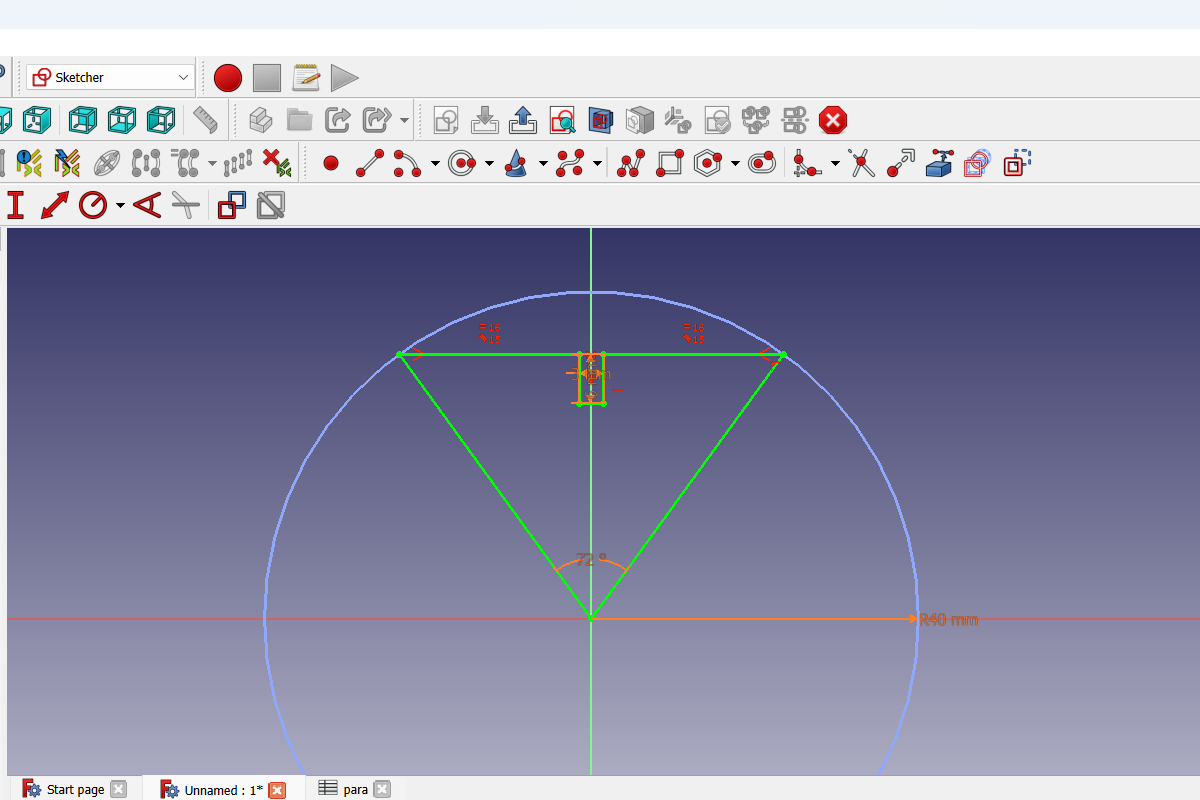 Here’s another viewgit
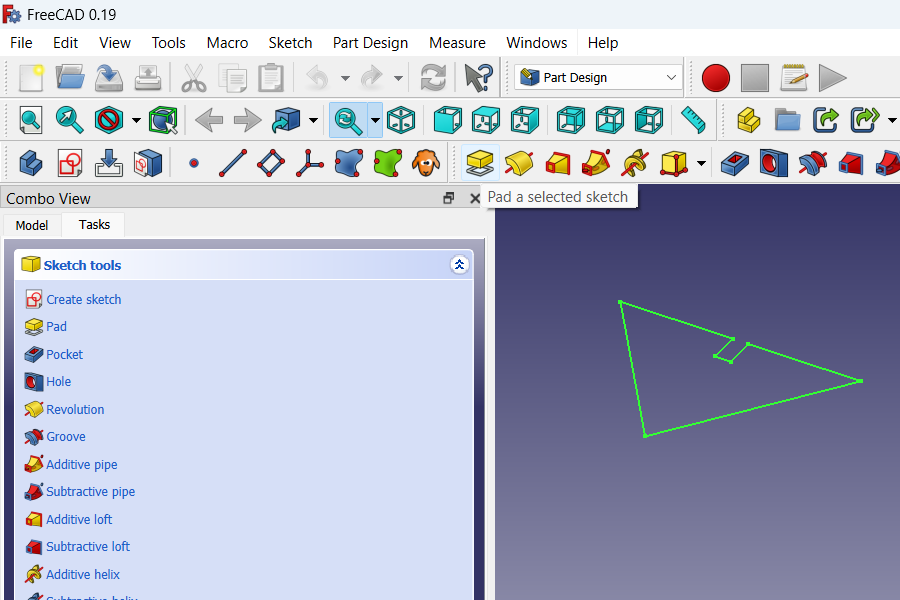
- You can already close Sketcher and go to Part Design. Then we need to mark our drawing and apply the extrude tool to it. You can immediately set the height using the parameter (Joint X).
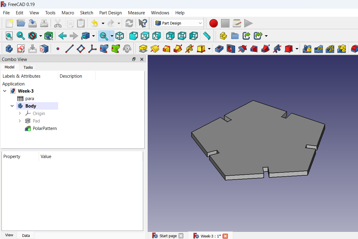
- Then you need to select the resulting element and apply the tool Polar Diagram to it. And in its parameters set our parameter number of segments.
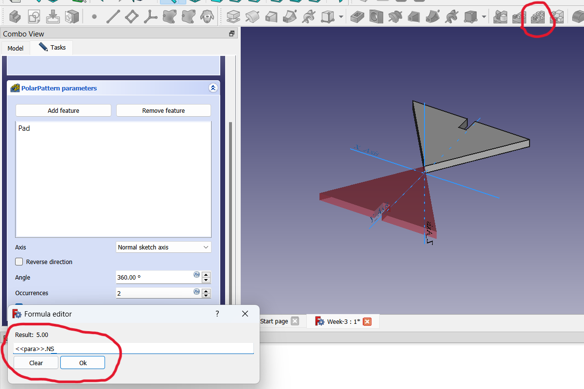
The result is a closed circuit.
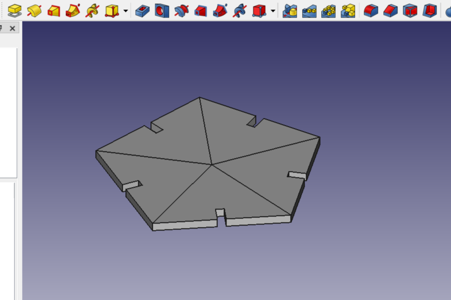
- In order for the body not to be divided into several segments, it must be connected together.
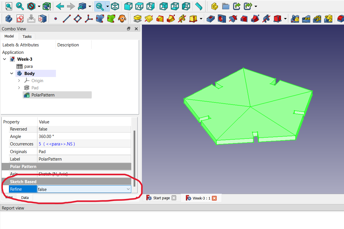
The result is a fully connected body. Which, if desired, you can change the parameters and a new object will be generated by which you can export as SVG and use in CoralDraw for laser cutting.
Laser cut kerf test draw
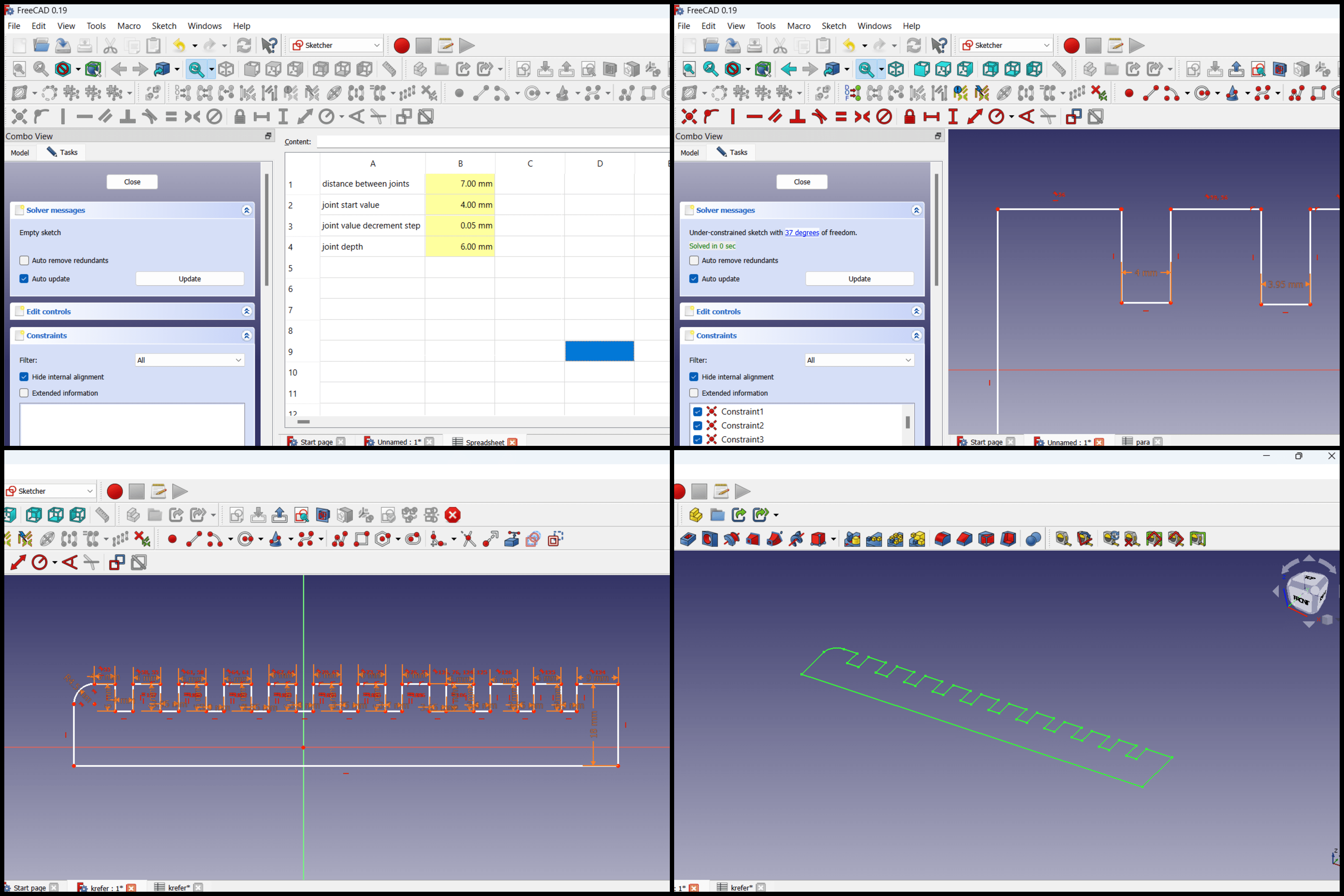
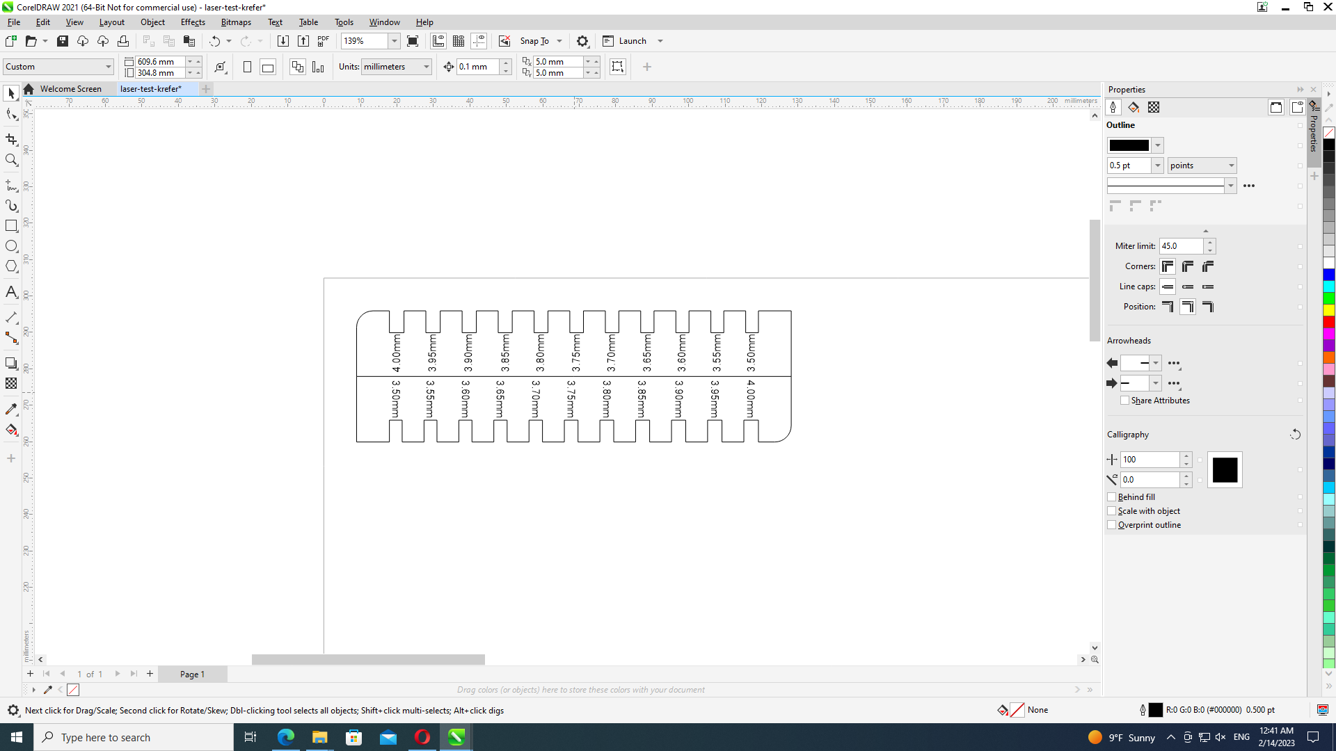
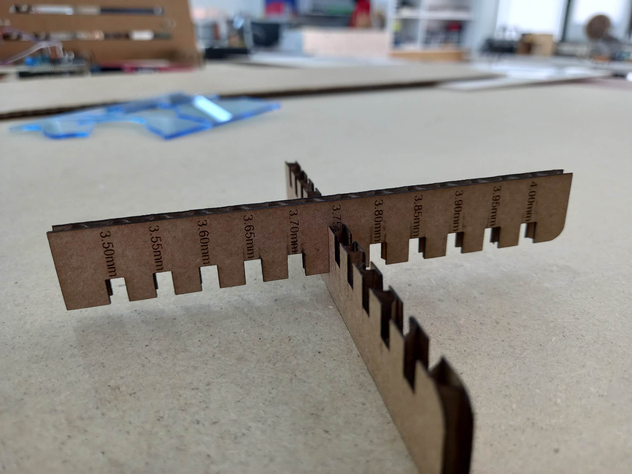
But before you start cutting the constructor, you need to conduct a test and understand how much material the laser takes when cutting, that is, how much makes up the awl of the laser beam. In my case, the thickness of the material is 4 mm. You need to figure out how to make the connection size so that the elements fit into each other tightly. To clarify this, I drew a test element that will answer this question. It includes from 4mm to 3.5mm holes with a step of 0.05 mm. I drew the test element in the FreeCad program as a parametric object. I will not go into details, just show a few photos:
Export 2D Drawing
Now let’s export the 2D drawing to be laser cut.
- Go to the Draft section
- Select an object
- Choose the location of the drawing TOP
- In the top menu Modification select Shape 2D view
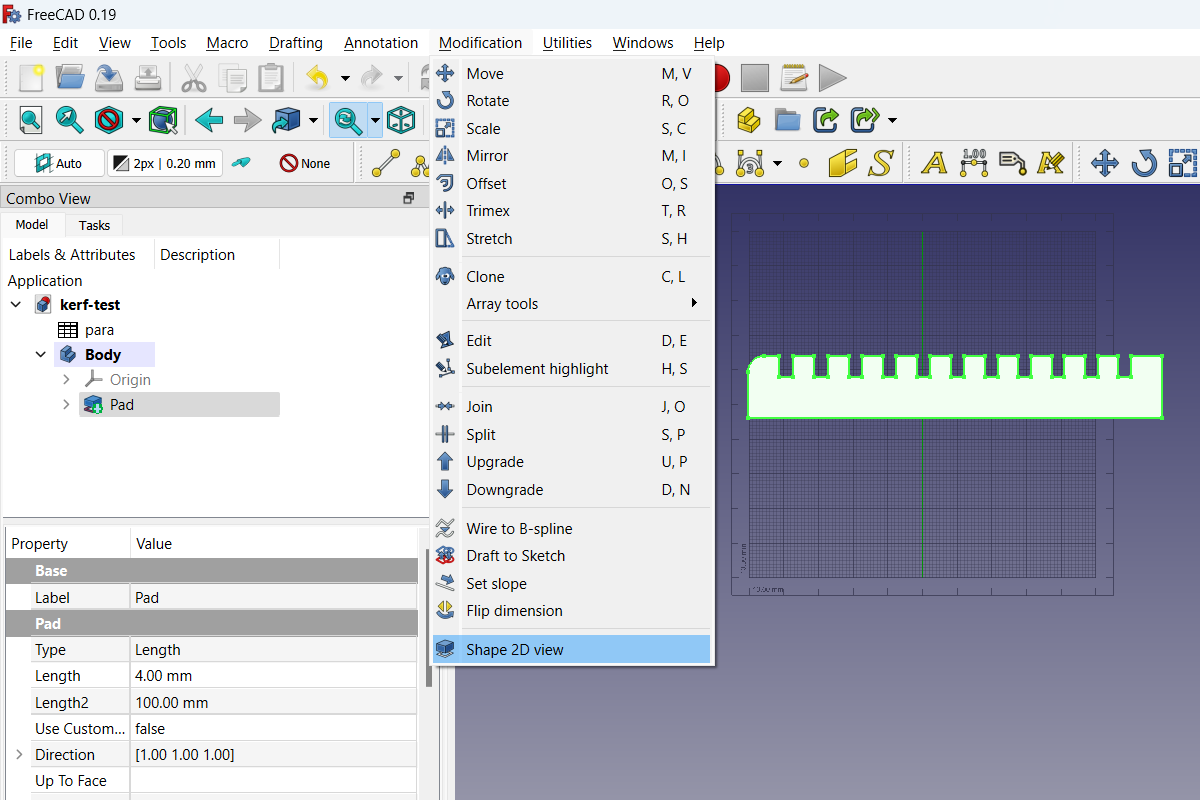
- This creates a flat drawing that can be exported in the format we need (File -> Export).
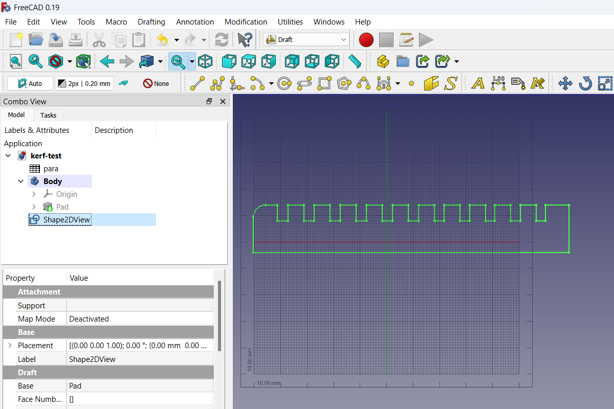
It is important to choose the location of the drawing, if the location is different, that is, this method gives us a projection of our 3D model, relative to how we look at it.
Laser cut kerf test
Our laser works through the program CorelDRAW 2021. I need to open the program CorelDRAW, create a new document, leave the default settings.
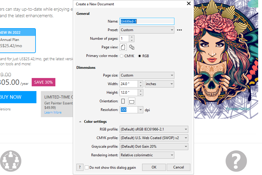
I create the document in 24 by 12 inches, as it corresponds to the size of our laser table, in the future I can change it so that the file is calculated in millimeters.
Then I just drag and drop the .dxf file I created into the program. I add text (hole sizes). Then I drag it to the place where I want to cut it.
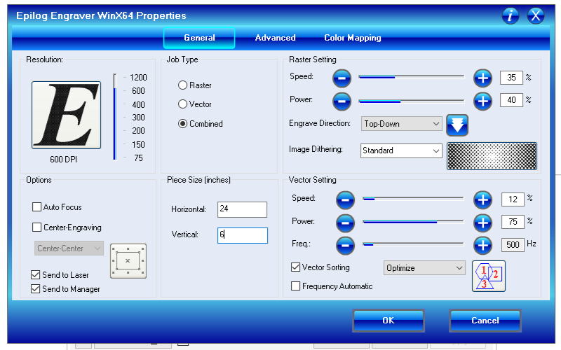
That’s it, now it’s time to raster and cut. There are two methods for determining focus, the first is manual and the second is automatic, in my case I chose the first option. As for the settings, I chose the settings that we received in the group task.
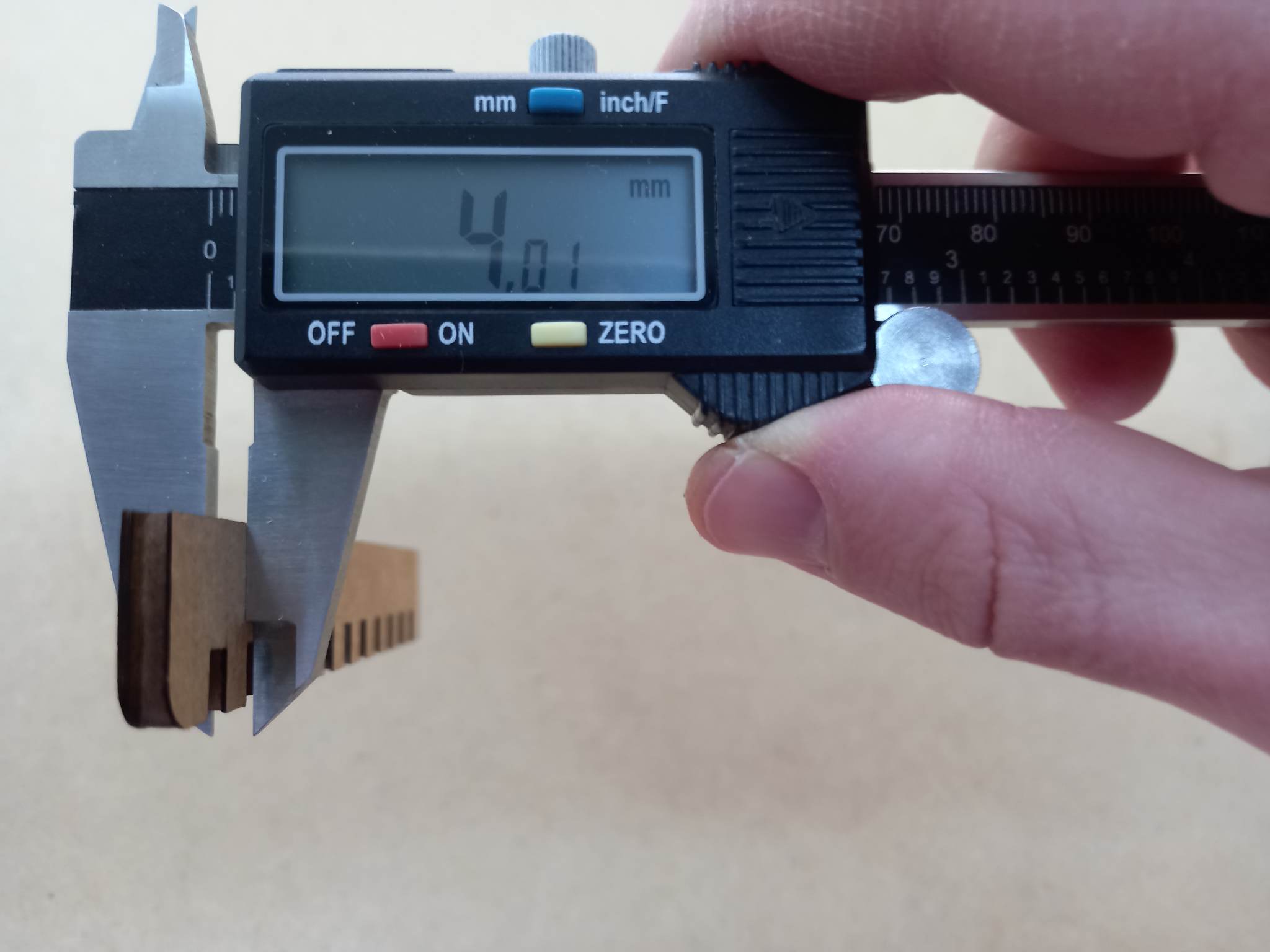
As an optimum value for 4.0mm plywood, I like the 3.75mm cut the best, it fits very well.
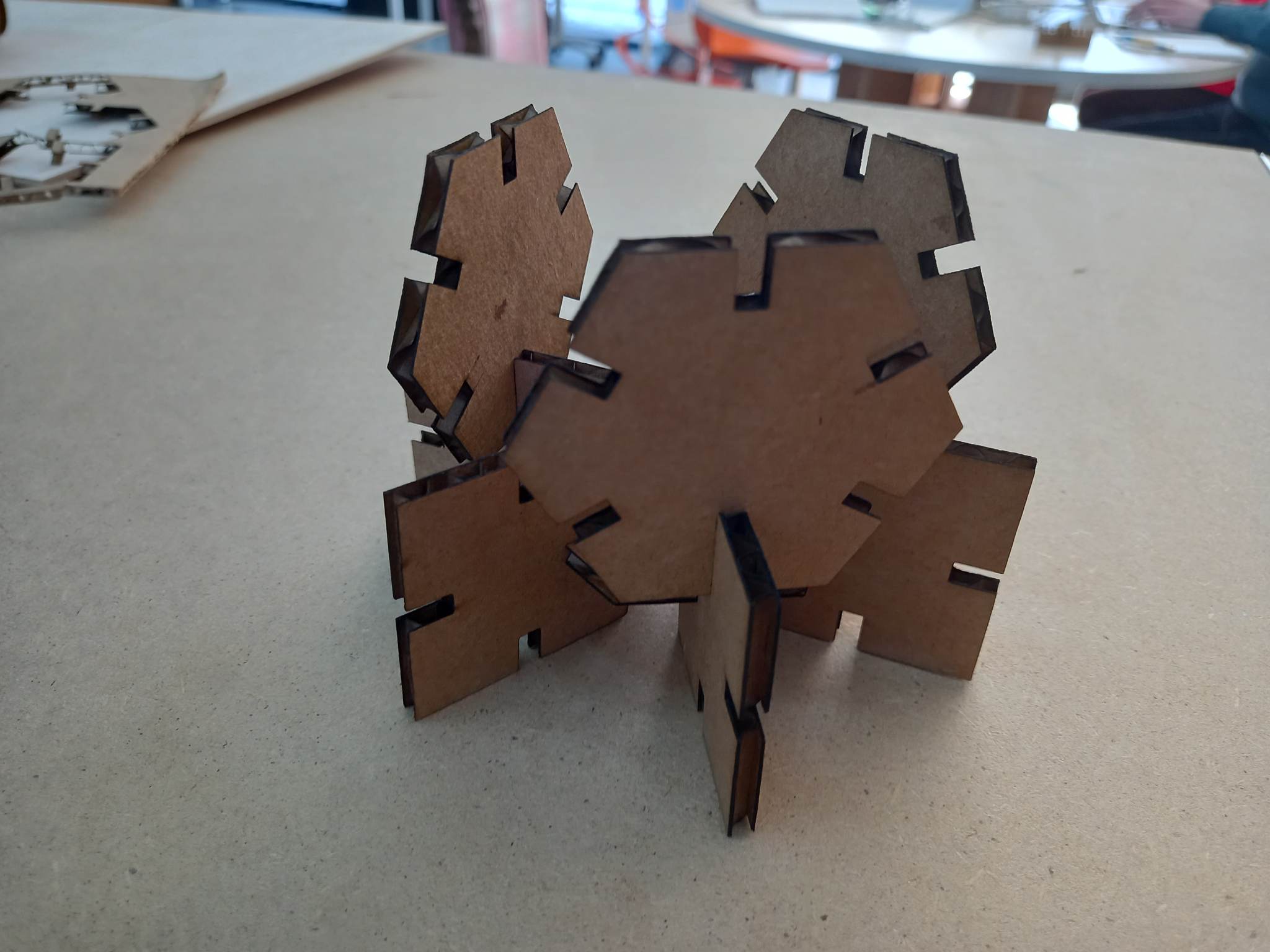
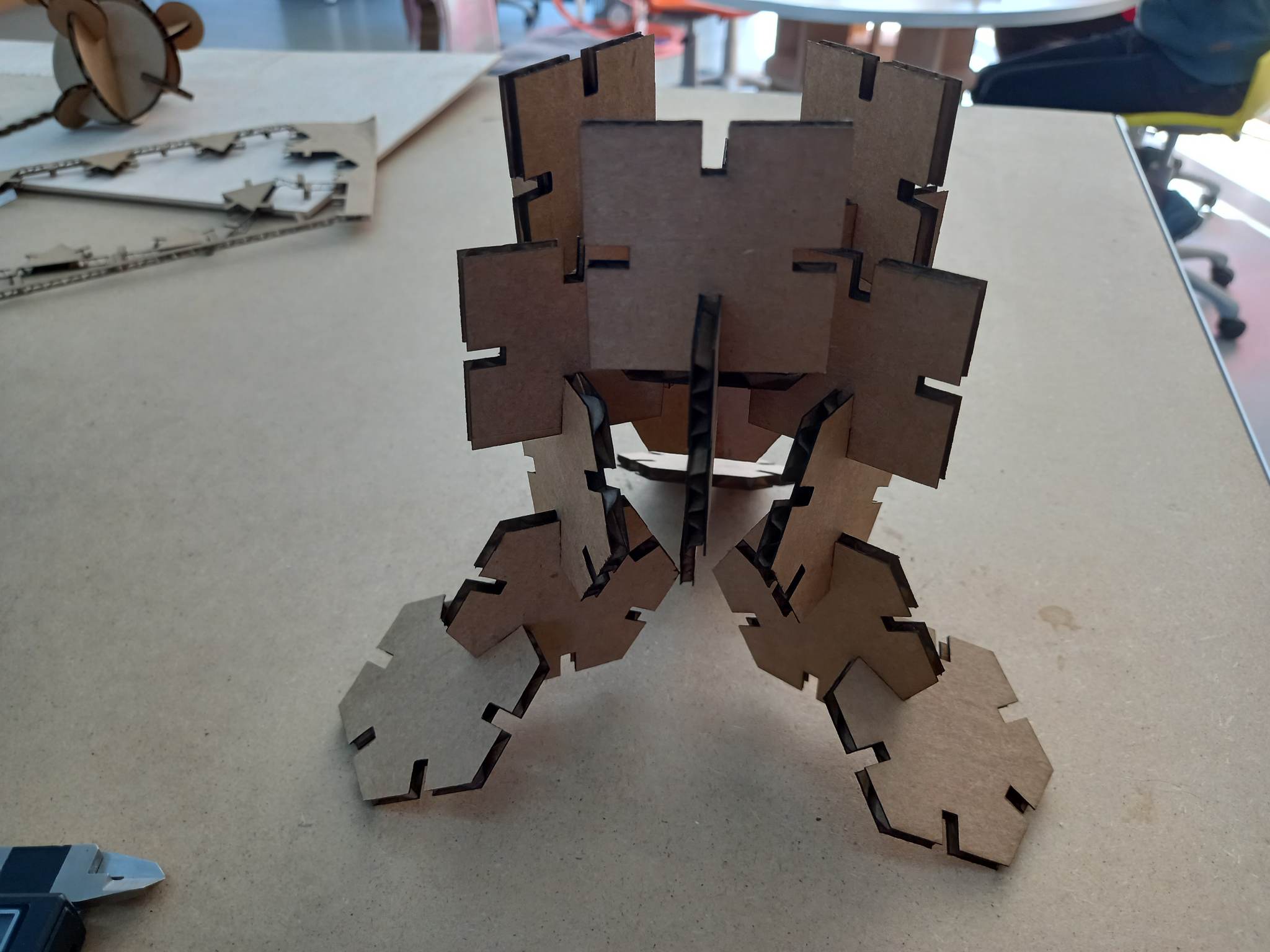
Laser cutting
Now that the test is done, you can change the joint width in the parameters to 3.75mm (Joint X), Number of segments (I chose 4 and 6).
Follow the steps that were taken in Export 2D Drawing.
Then the steps that were taken in Laser cut kerf test.
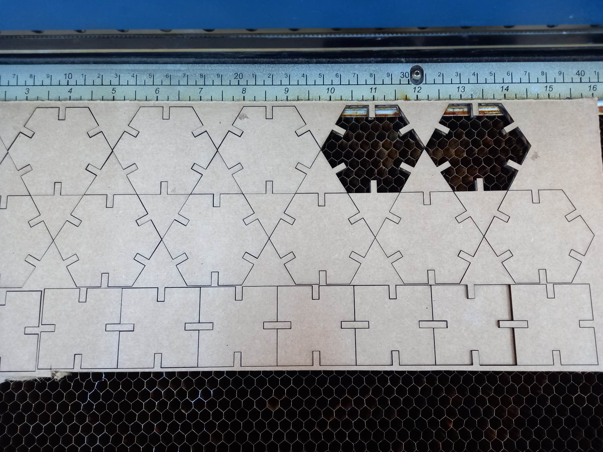
The result is as follows:
Links to Original Files
Vinyl Cutter
Laser Cut