9.Output Devices
Assignments
-individual assignment:
-add an output device to a microcontroller board you've designed,
-and program it to do something
-group assignment:
-measure the power consumption of an output device
Research
ATtiny KiCad library
XIO RP2040
SEEED XIAO rp2040 arduino
ADRIÁN TORRES SEEED XIAO rp2040 library
SEEED XIAO rp2040 KiCad library
stepper motor tutorial
Throughout The Week
Group
For group work this week me and my group tested the max and minimum voltages of a neo-pixle strip. It was not a lot of work, so we did it all together Group Site
Making the board
For this week I wanted to make a servo board that could control 7 servos using and using an external power supply for my final project.
V1
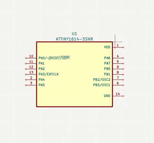
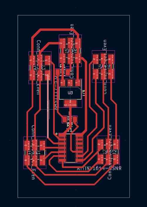
For my first version of my servo board I tried using a ATTiny 1614 microcontroller because while it is small it has enough pins for the seven servos I need. I have also had experience with the ATTiny 412 chip and though I might be able to transfer that code over. To start making the board I designed it in KiCad. I started by downloading the Attiny 1614 from the library linked above and adding it into the schematic.
I then added in a 3x2 header so that I could plug in the power ground and UDPI pin so that I could power and program the board. Then I just had to add headers for all the servos to be attached and add edge for the board to be cut.
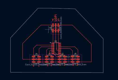
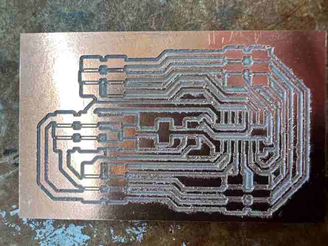
After I was done designing I milled the board out on the Batam Tool CNC Machine and here is the result of that.
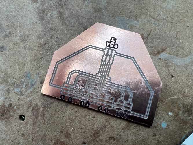
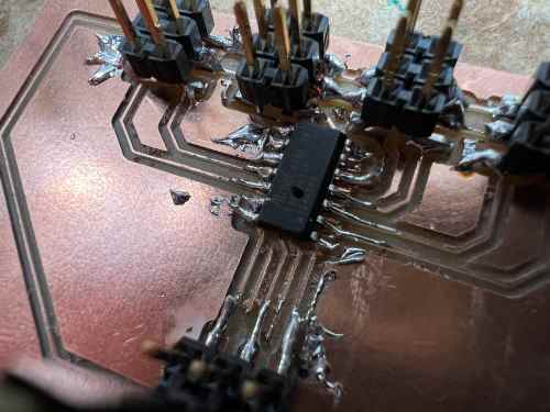
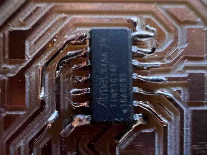
Then I had to solder the Atttiny 1614 chip on and the pin headers
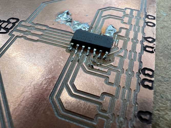
But then I realized I had made a big mistake. When testing the board I had just used an Arduino 5v power to supply as power for everything but when I plugged the 9 volt power supply in it immediately sparked and shorted from too much power going to the ATTiny 1614, so I had to redesign the board.
you can see the hole in the ATTINY in this image.
V2
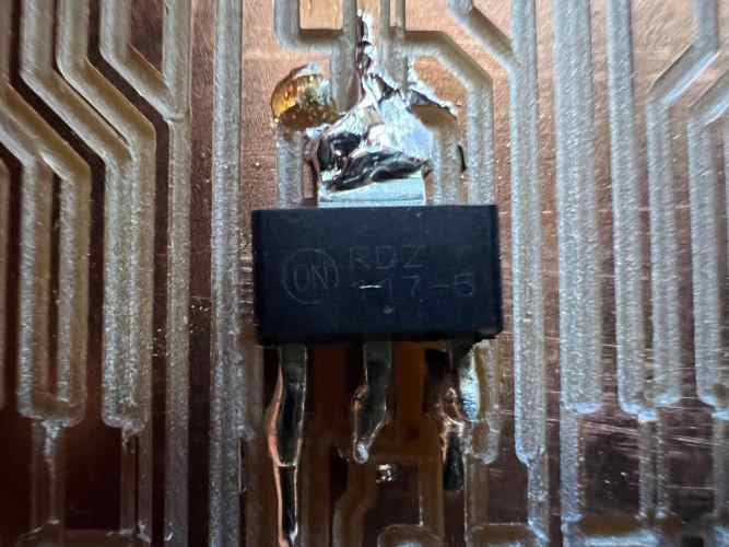
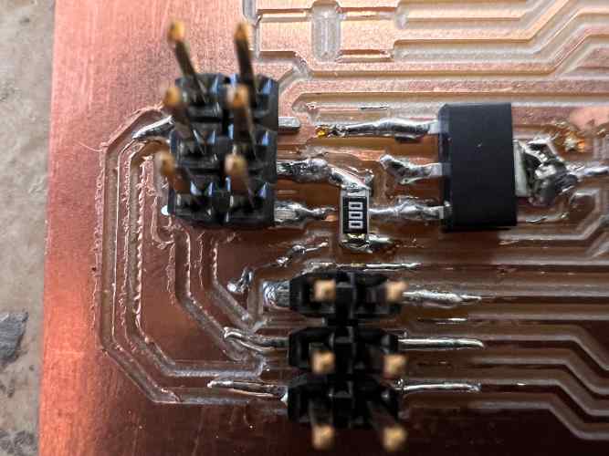
For version two of my board I had to figure out how to stop more than 5 volts from going into the ATTiny 1614 to do this Adam Durret my teacher and fellow fab academy student suggested a voltage regulator. After researching what that is and how it works to see if it would work I added it to my design in KiCad.
Here is a picture of the piece in question. It takes in all the power put into it and them contains it to 5 volts and lets it out through the big tab.
After I was done with the design I just had to mill to board out and solder it all.
Once it was soldered it worked with up to two servos as seen in this video.
This is when I realized a stupid mistake I made, because while it might work with two servos as soon as a third was added none of the servos could move their full value because they were not getting enough power. Because the 9 volt was not enough to power everything. I had known this prior, but I did not think that the 5 volt regulator would not be able to handle the 20-32v power I need for all the servos causing the 5v regulator to fry and not let any power through, causing me to get a NO_TARGET_POWER error when trying to upload code. Along with that I was getting many MCU_STATE_ERROR: NOT_VALID from the ATTINY 1614 and decided to scrap this board and use a SEEEDuino instead along with a better 5 volt regulators for it.
Realization
At this point right after week 10, because I was late for this week, is when I realized that I truly did not like this project idea and was not having any fun working on any parts of it. I realized this because when working on the Soda Machine during week 10 that even though their where parts that sucked every little success made me so happy, but any success with this project does not give me anything. So I decided so Switch projects and upgrade and improve the version one of the soda machine we made into a more refined process with many improvements. While I realize that I have already put a lot of work into this project I just do not find it worth it, So I would rather put my time and passion into something that I have fun making.
Because of this I am scrapping all progress on the servos because I had already gotten 4 to work and though that was good enough, and I switched to programming a stepper motor to learn how to use one for the soda machine.
Stepper motor
Because I had previously already designed a board for a microcontroller with an output device, I just needed a quick understanding of the stepper motor and how it works along with all its settings, so I hooked it all up to a H bridge motor controller to control the outputs for the stepper and not overheat the arduino. I then had to learn how to program it. Through a tutorial I learned all the code programs for it in Arduino that I could mess with. Here is that code and a video of the stepper motor spinning.
// Include the Stepper library:
#include <Stepper.h>


int stepsPerRevolution = 50;
const int speed = 200;


Stepper myStepper = Stepper(stepsPerRevolution, 8, 9, 10, 11);


void setup() {
  // Set the motor speed (RPMs):
  myStepper.setSpeed(speed);
  Serial.begin(9600);


}


void loop() {


  myStepper.step(stepsPerRevolution);
}
After getting the basic understanding of the code I then went through changing all the variables to truly understand what each command does and what would be best for the soda machine.
#include <Stepper.h> - This brings in the library for the stepper motor so that I can code it.
int stepsPerRevolution = 50; - this sets how many steps it takes for the stepper motor to do a full rotation. It can go as low as 1 and as High as 200. At one each step turns the motor 360 degrees but at 200 it turns the motor 1.8 degrees giving me much more control of where it goes.
myStepper.setSpeed(speed); - this sets the speed of the motor. It means how many steps it will do per second. Meaning that right now it does 4 rotations per second.
Stepper myStepper = Stepper(stepsPerRevolution, 8, 9, 10, 11); - This sets the stepper motor to digital pins 8,9,10,11 and sets how many steps it takes per revolution.
myStepper.step(stepsPerRevolution); - Lastly is the step command. This makes the stepper motor actually turn a certain amount of steps. It can be both negative and positive making it turn right and left.
Summary
This week I learned how to control voltage with a voltage regulator and how to use external power supply to power a circuit. I also learned how a stepper motor works and how to control it with its many code commands. With this I will be able to design a circuit to have the many input and output devices I will have on my new final project. I also will be able to control the carriage with lots of precision with the stepper motor allowing me to not spill more liquids.