My Final Project
For my final project I want to create a digital clock that has the blocks be pushed out by servos to relay the time. I want it to be able to connect to the wifi to figure out the time and maybe for me to be able to switch it into timer mode. when in timer mode you cna set a timer with a key pad on the side and it will count down.
Original planning
When I first started to think more about a final project I would like to make At first I was thinking I could make a type of alarm clock, then I though about a table that would show where I am at all times becuase its connected to my phone but then I figured out that I want to make a digital clock where the blocks come out of the clock being moved by servos. I want it to connect to the internet and maybe for it to be able to turn into a stopwatch/timer. Here are all the images with notes I wrote about how each item works and want I want To do plus look like. This is just a prototype becuase if I can find a more effieceint and reliable method to move the block up and down I will use that.
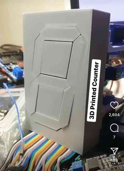
The blocks are in in this picture from an instagram post I found.
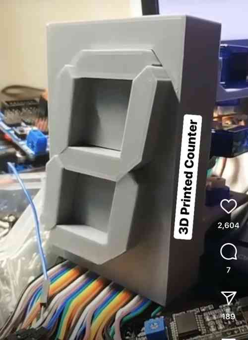
The blocks are out in this picture from and instagram post I found.
![]()
The Instagram logo links to a instagram post that I found that I would love for my final to work like.
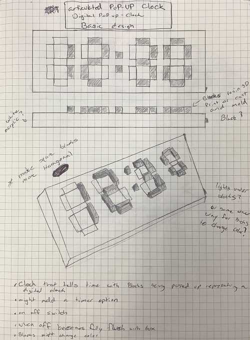
This pages show the clock as a whole. I started with what I wanted it to look like so I did not think about how it would work at first. The hardest part about this project is the up and down system because I need a quick and easy method to move the blocks up and down while also being cost and time effieceint.
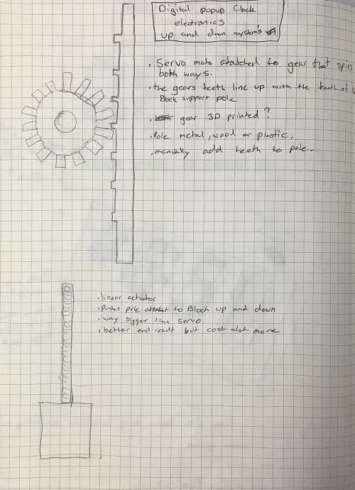
Thats why I though up using servos becuase they are quick, reliable and accurate. Then for how the servo will move it I remebered gears amd how with their teeth they can push stuff up and down so I decided to go with what is drawn above.
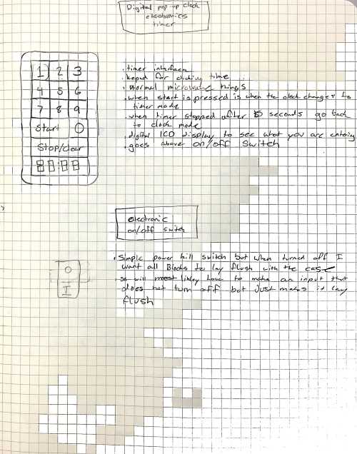
As you can see I want to make a key pad that turns the clock into a timer for whatevr time you set. there will be a mini led LCD display so you can see what time you have put in and once that happens you can hit start to start the timer. I would also like to add a switch that makes the whole clock lay flush with the case and then turn it off.
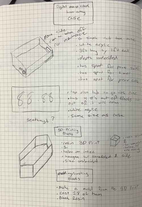
For the case I am thinking just a normal tab box made out of white acryic thats around 3 feet by 1 foot big. for the blocks that move up and down I want to resin 3D print 1 then mold it and cast the rest. The blocks will be hollow on inside for more space.
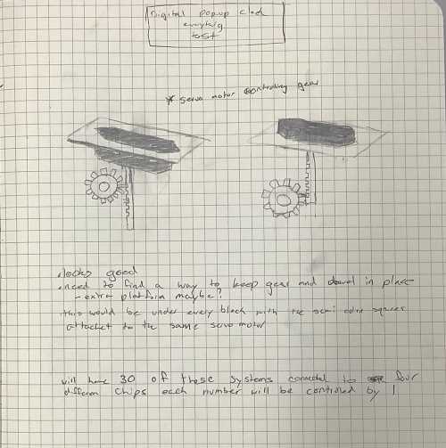
This last page is a basic sketch of one servo system put together with the servo turning the gear and the gear pushing the dowl up and down. I will need to make 30 of these for the whole clock.
Original Designs
PhotoShop
Here is a simple Raster design of what I want my Project to look like from PhotoShop. I desgined it to see what the sizing my plans looked like. After desining it for the first time I though their was too much empty space so I made it smaller into what you see now.
CorelDraw
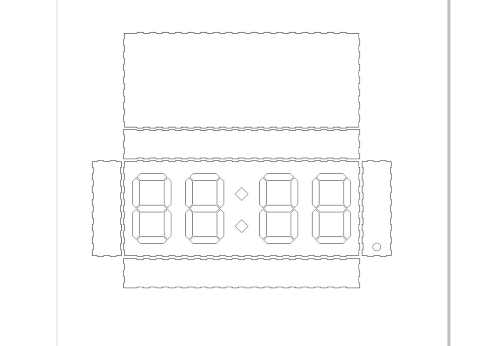
This image shows my vector drawing of my final project case as a tab box so that I can cut it on the laser cutter later. It has spots for hinges so that I can open and close the back to get to the electronics and has the a spot for the blocks cut out on the front.
Fusion 360
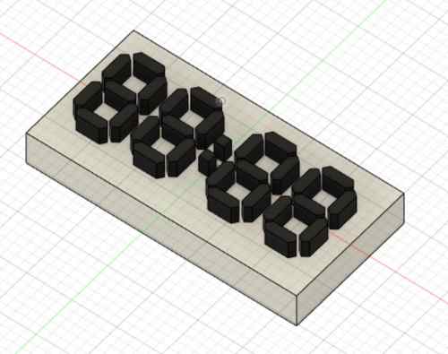
This image shows my 3d modle of what I want my final project to look like. I designed it in fusion and it too look just like this. White arcylic with black blocks.
Prototyping
laser Cutting
I started my prototyping by laser cutting a test single digit box of my final project to see the sizing and so I could build an easy tester to see what the final version might look like. this way I can try many ways off making the blocks go up and down and if it breaks it does not matter.
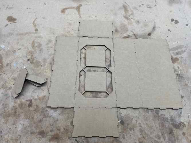
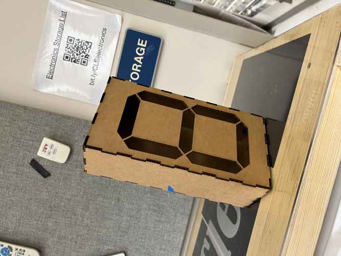
These images show my test box that I plan to use to prototype my whole system for my final clock.
3D printing
Gear system
V1
I have a bunch of thing I have to 3D print for my project but Ill start off with my gear system to move things up and down. I designed in in fusion 360 and then animated it so here is the animation. as you can see it has a spot for the servo motor to slip into so I can control it.
and here is a video of my gear spinnign with a servo motor.
V2
after I made sure my idea worked I designed a smaller more compact version that can actually fit in my clock. So I completely restarted my design and made a capsule for it that is small enough for the block to come over it. Then I remade the gear and block gear so that they will be held in place, so that it will work as intended. Here is an animation of the file.
Blocks / Digits
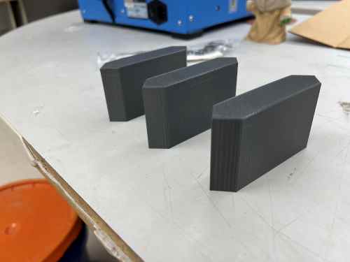
For the actual blocks for my final project I designed them in fusion 360 by using my DXF file for my single digit and extruding it up. I then left it because with the Kerf of the laser cutter there is just enough room for it to slide up and down without getting stuck. Here is the printed version that I will later cast and mold to make the final version of my blocks.
Board Design
V1
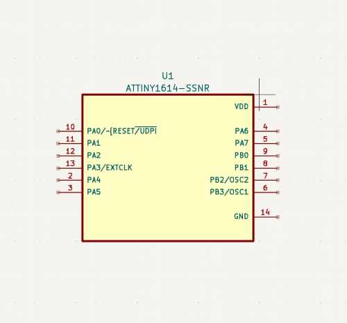
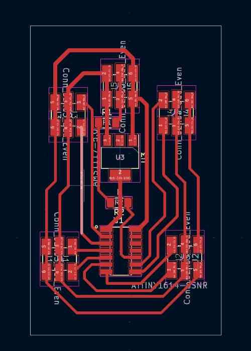
For my first version of my servo board I tried using a ATTiny 1614 microcontroller because while it is small it has enough pins for the seven servos I need. I have also had experience with the ATTiny 412 chip and though I might be able to transfer that code over. To start making the board I designed it in KiCad. I started by downloading the Attiny 1614 from the library linked above and adding it into the schematic.
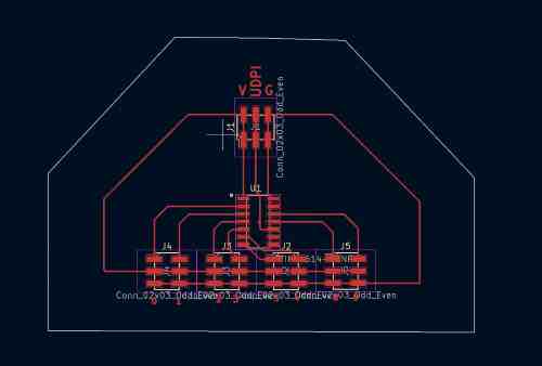
I then added in a 3x2 header so that I could plug in the power ground and UDPI pin so that I could power and program the board. Then I just had to add headers for all the servos to be attached and add edge for the board to be cut.
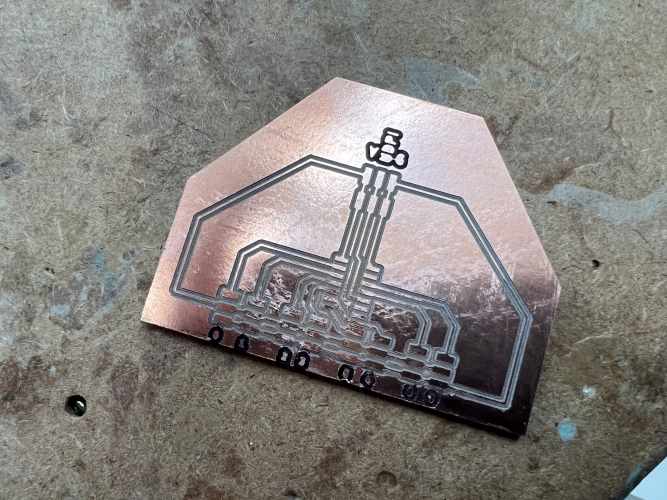
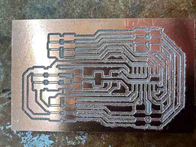
After I was done designing I milled the board out on the Batam Tool CNC Machine and here is the result of that.
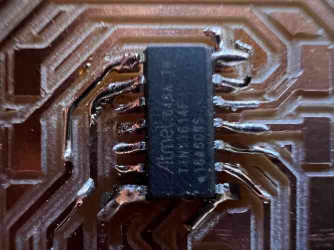
Then I had to solder the Atttiny 1614 chip on and the pin headers
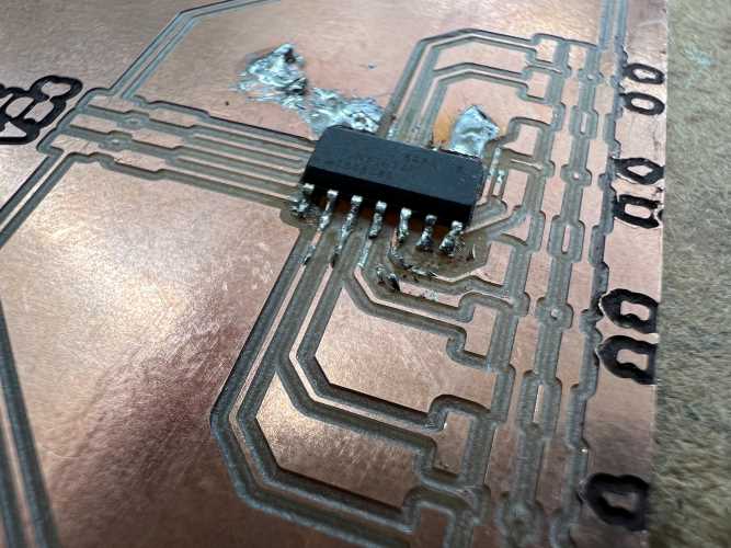
But then I realized I had made a big mistake. When testing the board I had just used an Arduino 5v power to supply as power for everything but when I plugged the 9 volt power supply in it immediately sparked and shorted from too much power going to the ATTiny 1614, so I had to redesign the board.
you can see the hole in the ATTINY in this image.
V2
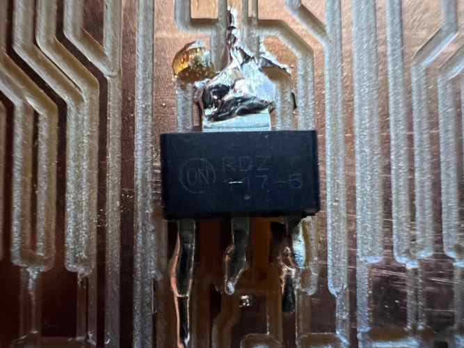
For version two of my board I had to figure out how to stop more than 5 volts from going into the ATTiny 1614 to do this Adam Durret my teacher and fellow fab academy student suggested a voltage regulator. After researching what that is and how it works to see if it would work I added it to my design in KiCad.
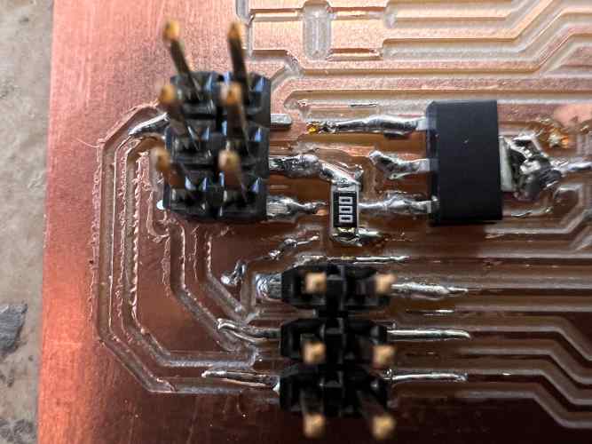
Here is a picture of the piece in question. It takes in all the power put into it and them contains it to 5 volts and lets it out through the big tab.
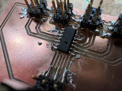
After I was done with the design I just had to mill to board out and solder it all.
Once it was soldered it worked with up to two servos as seen in this video.
This is when I realized a stupid mistake I made, because while it might work with two servos as soon as a third was added none of the servos could move their full value because they were not getting enough power. Because the 9 volt was not enough to power everything. I had known this prior, but I did not think that the 5 volt regulator would not be able to handle the 20-32v power I need for all the servos causing the 5v regulator to fry and not let any power through, causing me to get a NO_TARGET_POWER error when trying to upload code. Along with that I was getting many MCU_STATE_ERROR: NOT_VALID from the ATTINY 1614 and decided to scrap this board and use a SEEEDuino instead along with a better 5 volt regulators for it. I did this because all these errors along with having to try and figure out why JTAG was not working for me, was honesty frustrating me and making me waste so much time, so I decided to switch to something I could finish on time.
Realization
At this point right after week 10 is when I realized that I truly did not like this project idea and was not having any fun working on any parts of it. I realized this because when working on the Soda Machine during week 10 that even though their where parts that sucked every little success made me so happy, but any success with this project does not give me anything. So I decided so Switch projects and upgrade and improve the version one of the soda machine we made into a more refined process with many improvements. While I realize that I have already put a lot of work into this project I just do not find it worth it, So I would rather put my time and passion into something that I have fun making.