Input Devices
Group assignment:
Individual assignment:
A sensor is everything that has a property that is sensitive to a magnitude of the medium, and by varying this magnitude the property also varies with a certain intensity, that is, it manifests the presence of said magnitude, and also its measurement.
A sensor in industry is an object capable of varying a property in the face of physical or chemical magnitudes, called instrumentation variables, and transforming them into electrical variables with a transducer. The instrumentation variables can be for example: light intensity, temperature, distance, acceleration, inclination, pressure, displacement, force, torque, humidity, movement, pH, etc. An electrical quantity can be an electrical resistance (as in an RTD), an electrical capacity (as in a humidity sensor), an electrical voltage (as in a thermocouple), an electrical current, etc.
A sensor differs from a transducer in that the sensor is always in contact with the magnitude that conditions it or the instrumentation variable, with which it can also be said that it is a device that takes advantage of one of its properties in order to adapt the signal it measures. so it can be interpreted by another device. For example, the mercury thermometer that takes advantage of the property of mercury to expand or contract due to the action of temperature. A sensor can also be said to be a device that converts one form of energy into another.
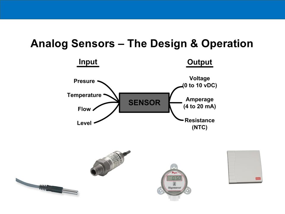
An analog sensor produces continuously varying output signals over a range of values. Usually the output signal is voltage and this output signal is proportional to the measurand. The quantity that is being measured like speed, temperature, pressure, strain, etc. are all continuous in nature and hence they are analogue quantities A thermocouple or a thermometer is an analog sensor. The following setup is used to measure the temperature of the liquid in the container using a thermocouple.
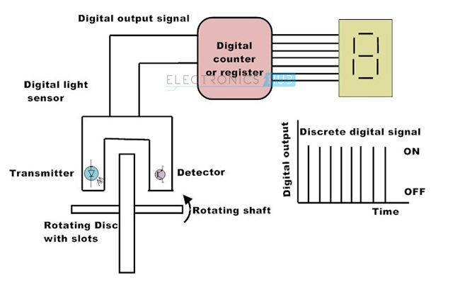
A digital sensor produces discrete digital signals. The output of a digital sensor has only two states, namely ‘ON’ and ‘OFF’. ON is logic 1 and OFF is logic 0. A push button switch is the best example of a digital sensor. In this case, the switch has only two possible states: either it is ON when pushed or it is OFF when released or not pushed. The following setup uses a light sensor to measure the speed and produces a digital signal. .
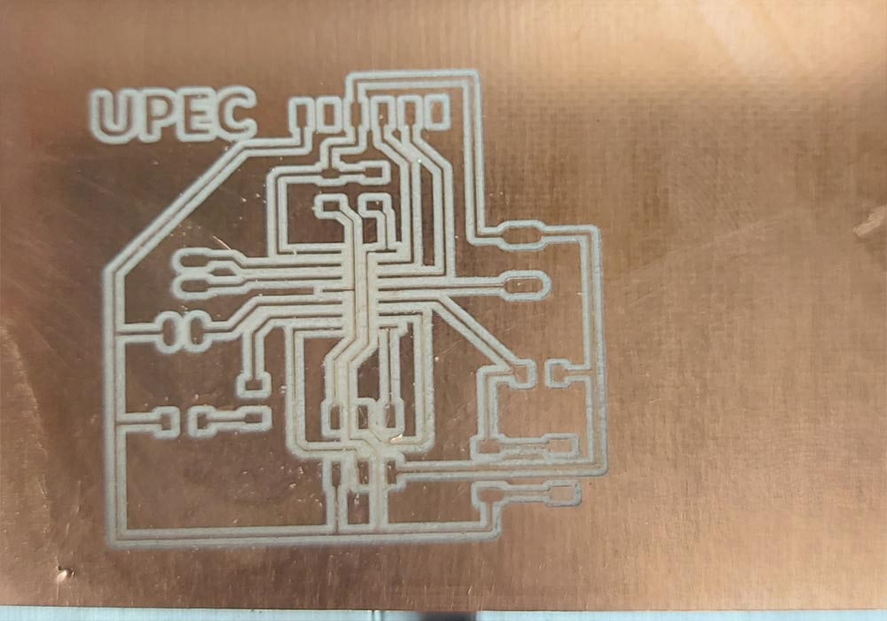
For this assignment we will use the same design used in embedded programming since this design has free pins to connect our sensor, You can watch the entire creation process and download the files at the following link, embedded programming
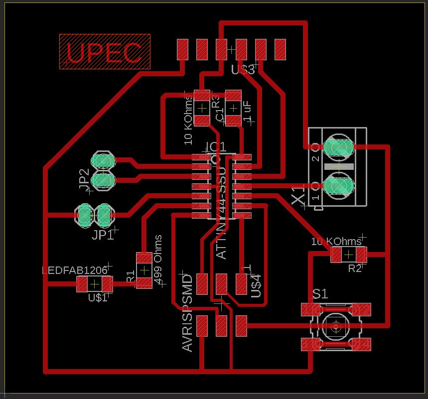
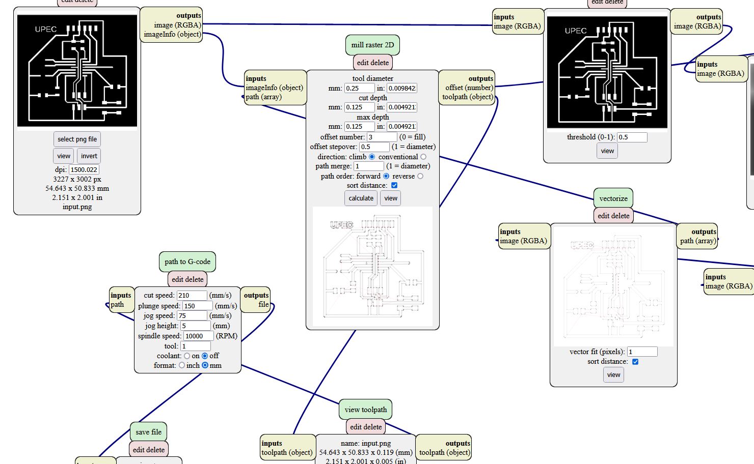
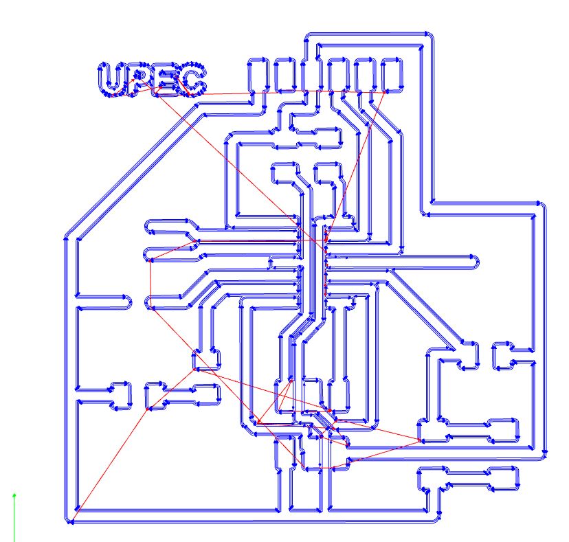
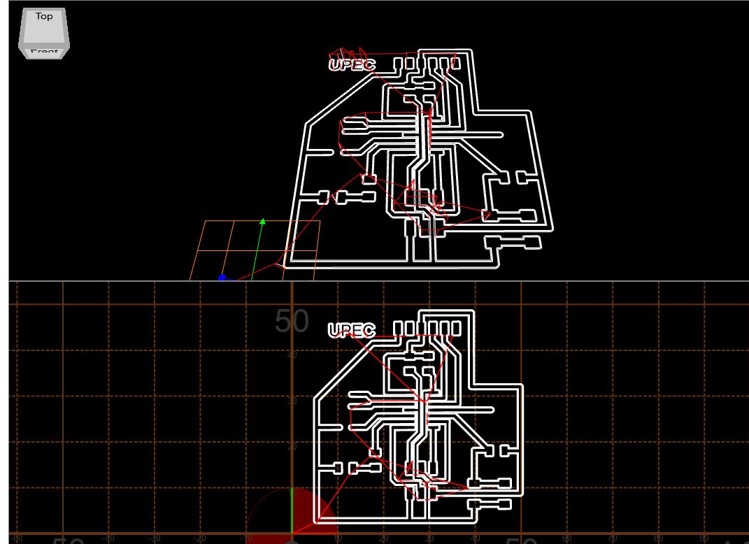
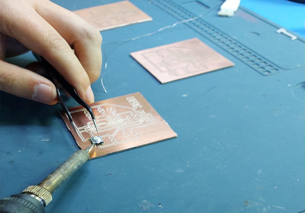
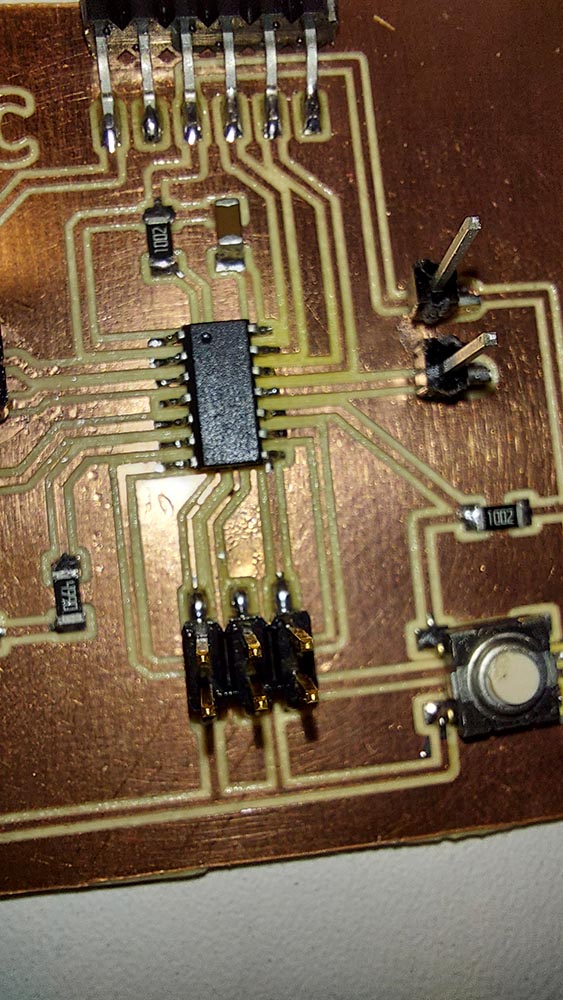
Once the design was finished in Eagle, the simulation of the g code was carried out, in which the verifications were made if all the tracks are correct, when this step was completed, the circuit board was manufactured in the cnc, and then began with the Soldering of the elements
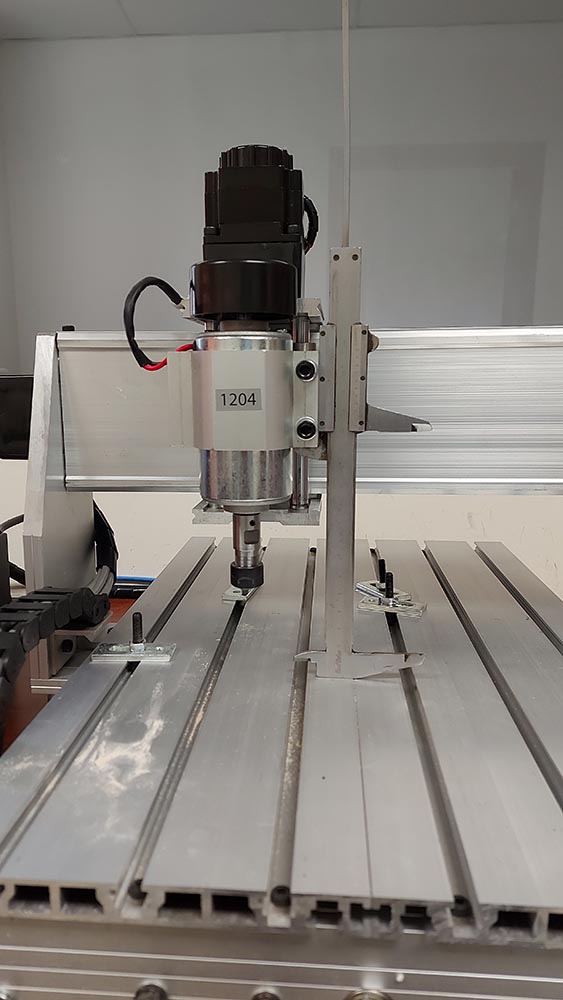
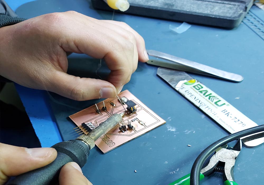
Below we can see the entire manufacturing process of our input board, for this we use our desktop cnc, the entire manufacturing process can be observed in more detail in the following link ElectronicDesig
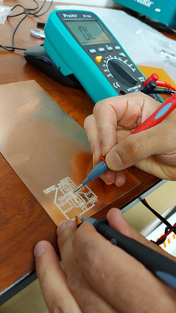
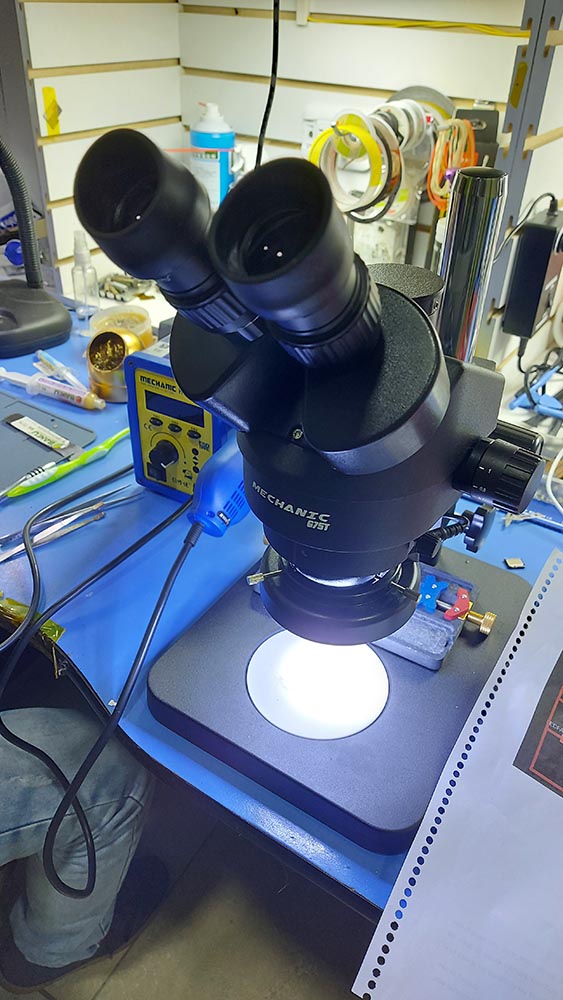
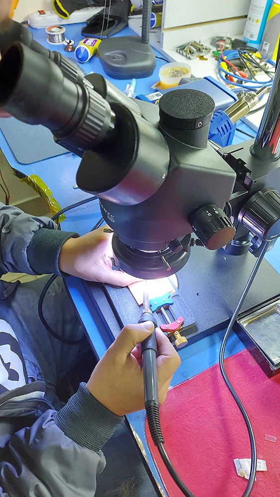
To weld the elements we use a microscope, the truth is not necessary, but it helps a lot to achieve better welds
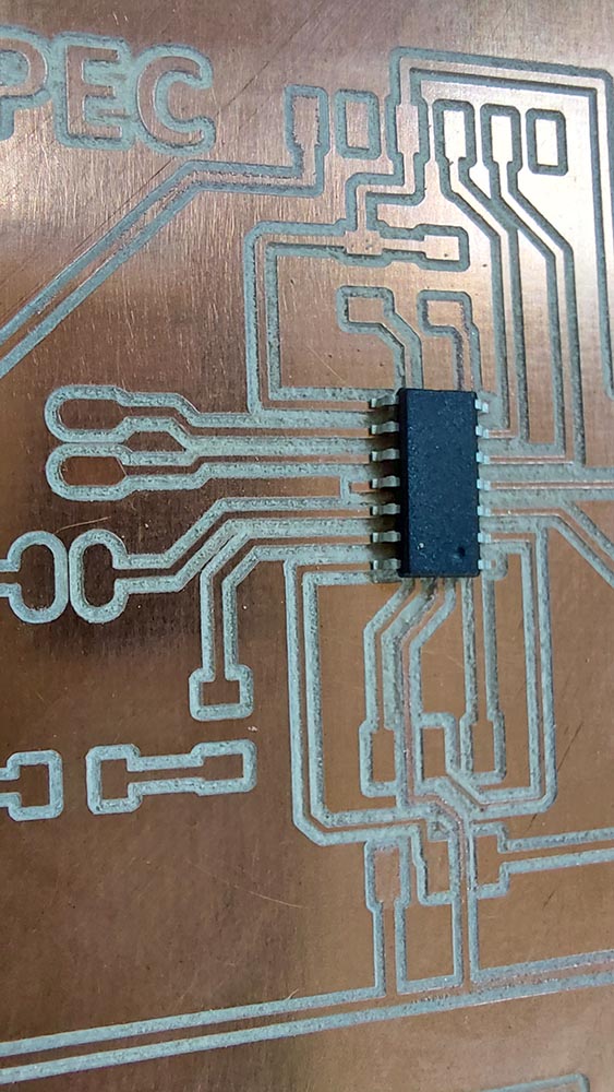
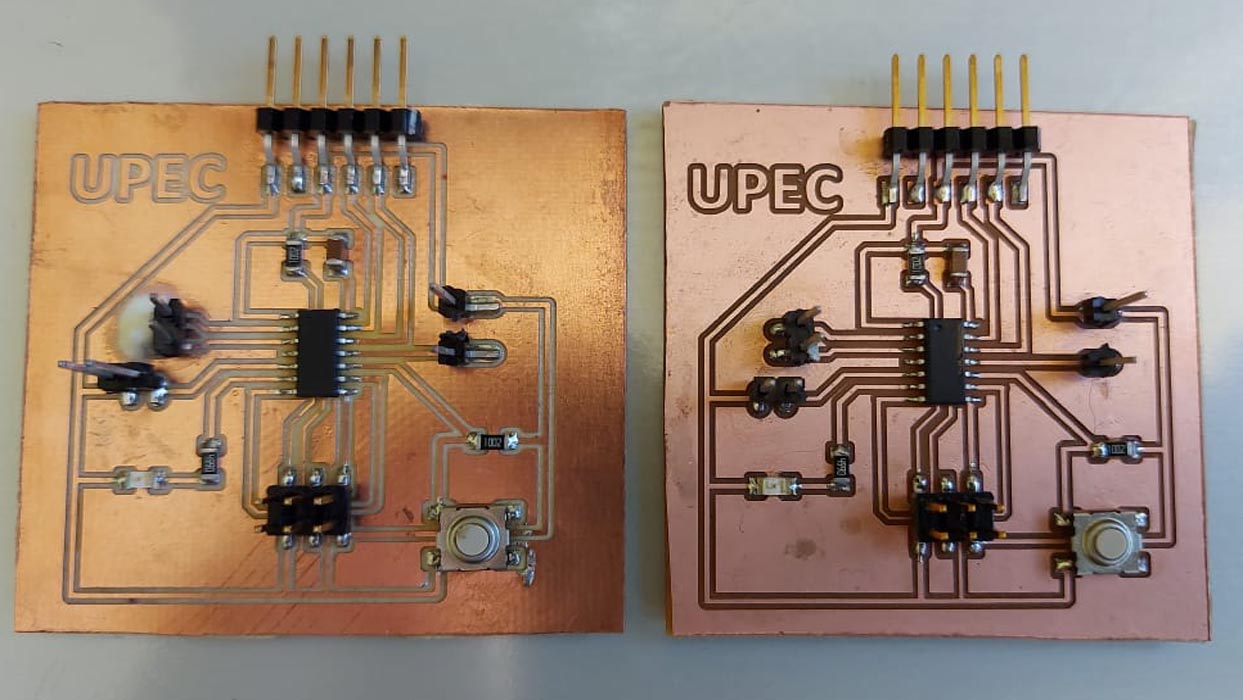
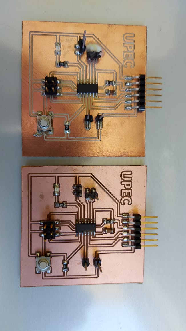
During the manufacturing process, I made several pcb boards, the more I manufactured, the more experience I gained in their manufacture, testing various milling parameters, and being able to weld repeatedly, each time achieved better results.
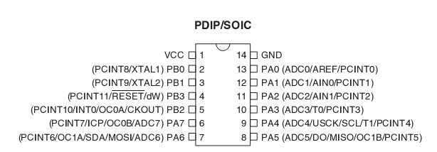
Initially it was necessary to know and be able to correctly identify the pins of the ATtiny 44 to be able to make the connections properly, for this the Datasheet was used, this can be found in the following link ATTiny44
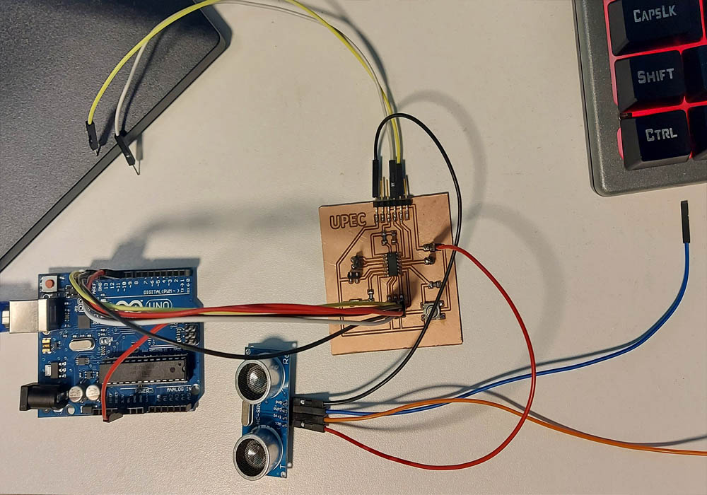
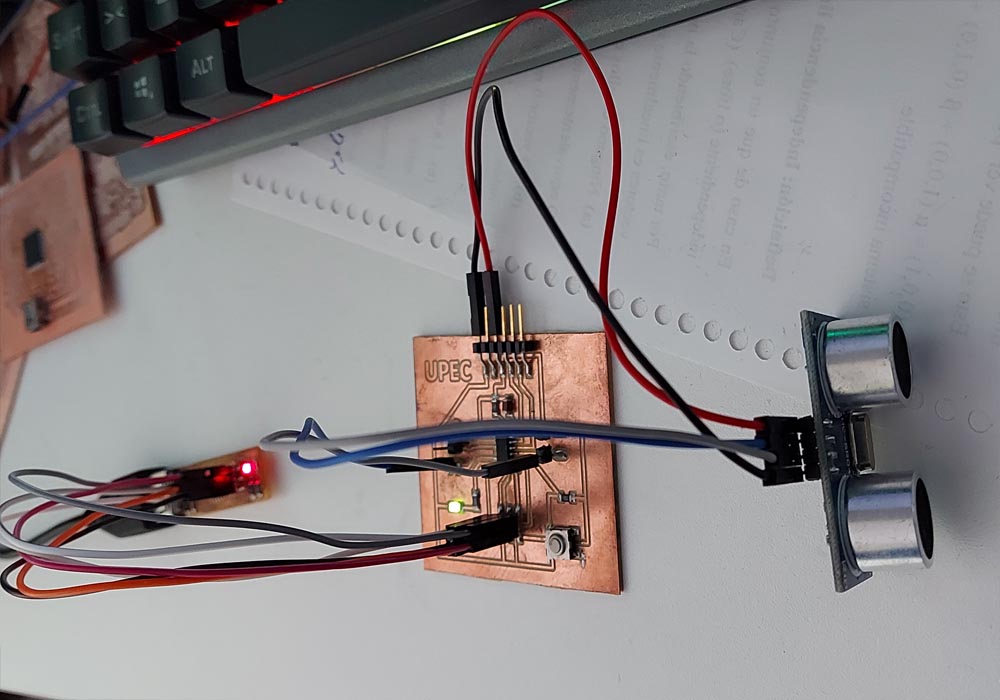
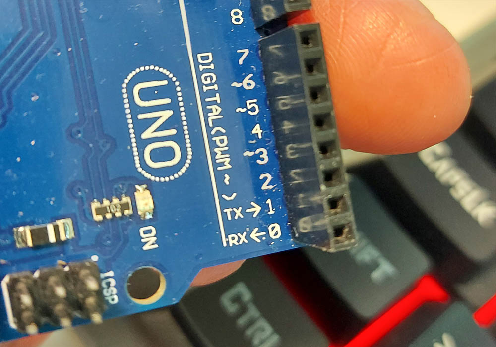
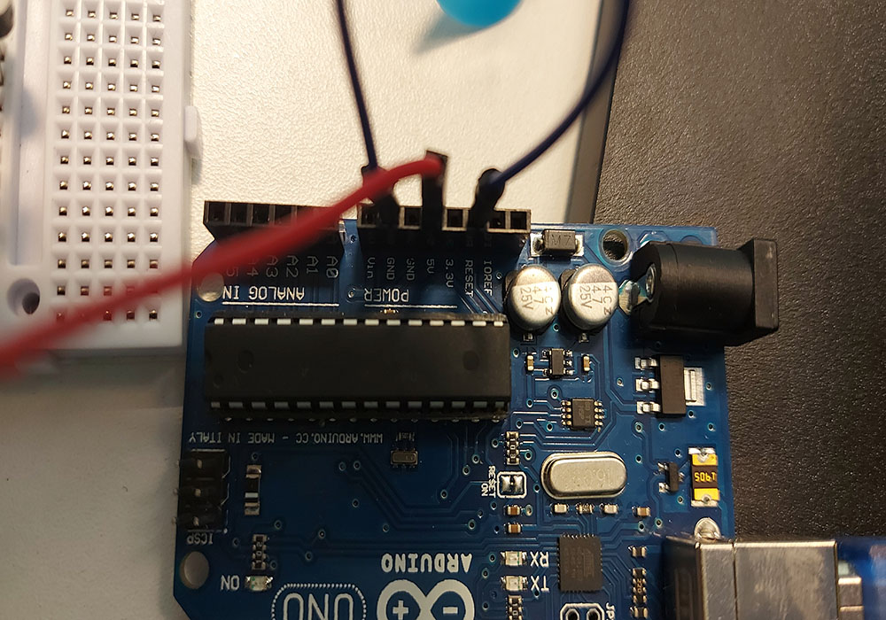
We will connect a proximity sensor to our circuit, For this we will first use our Arduino as a programmer, and we will load the code to control the proximity sensor, In addition, we will control the parameters indicated in the code with the on and off of a led integrated in the circuit board
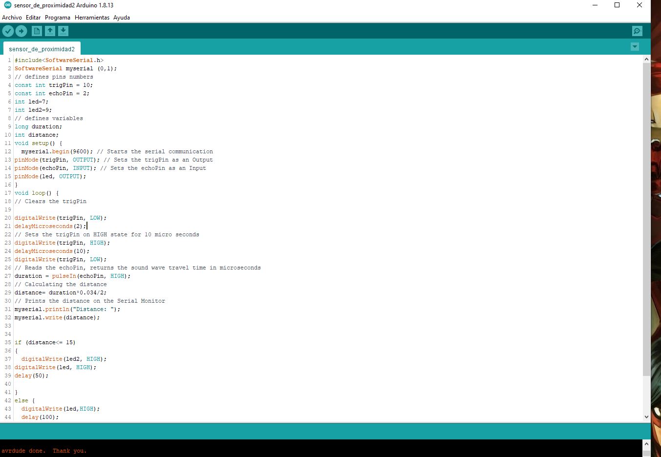
Once I finished testing the proximity sensor and understood its operation and programming, I went on to program the circuit with the UsbTiny programmer
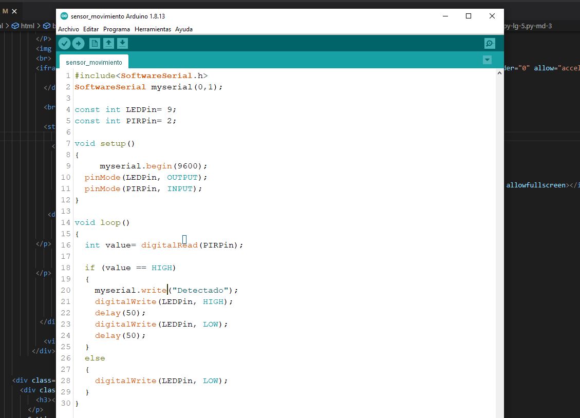
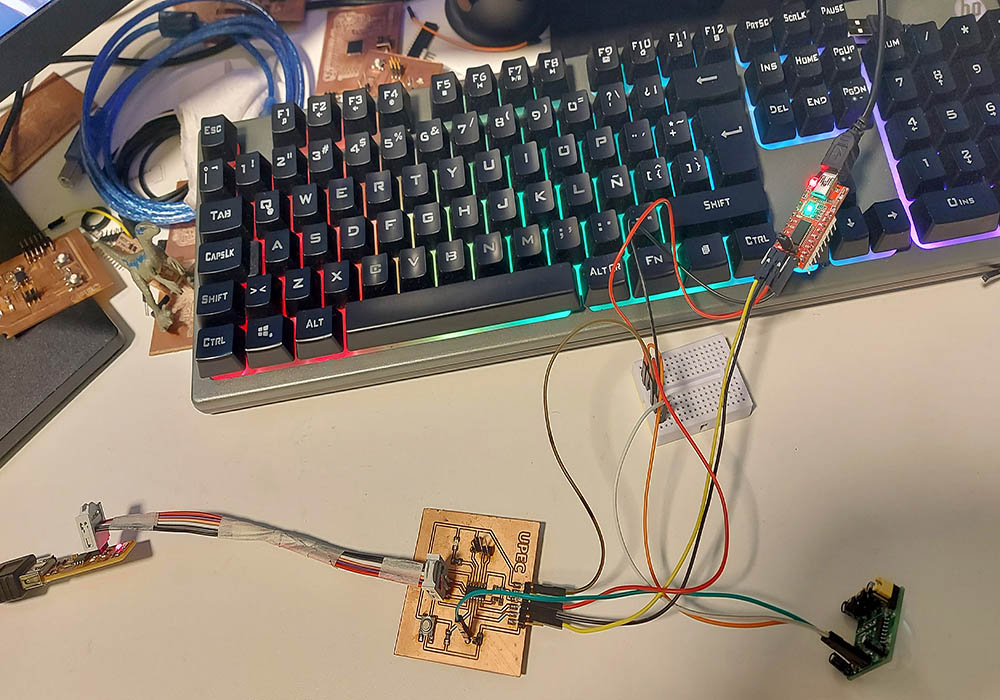
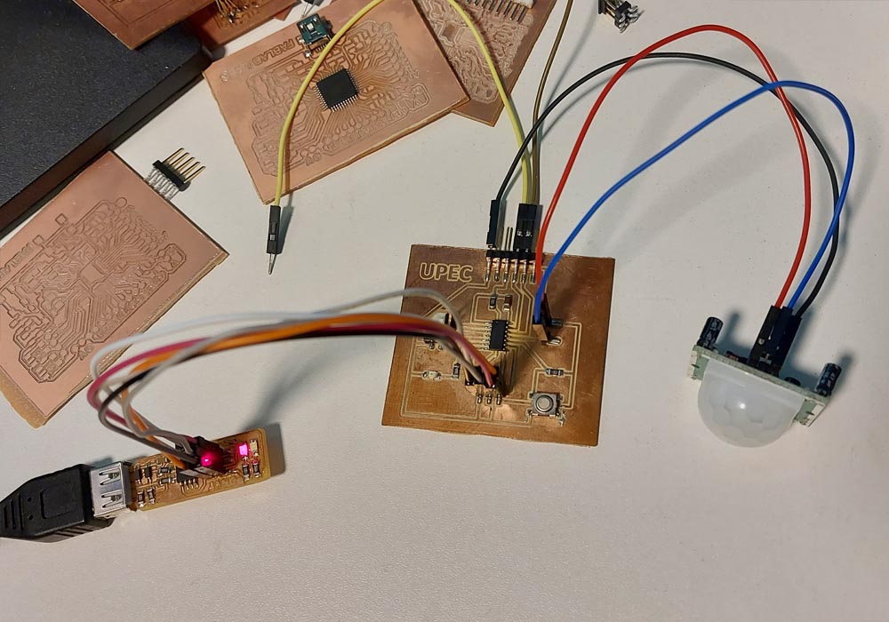
in this occasion we will connect a movement sensor to our ATtiny44 controller, in the following images we can see the connections and the necessary code for its operation
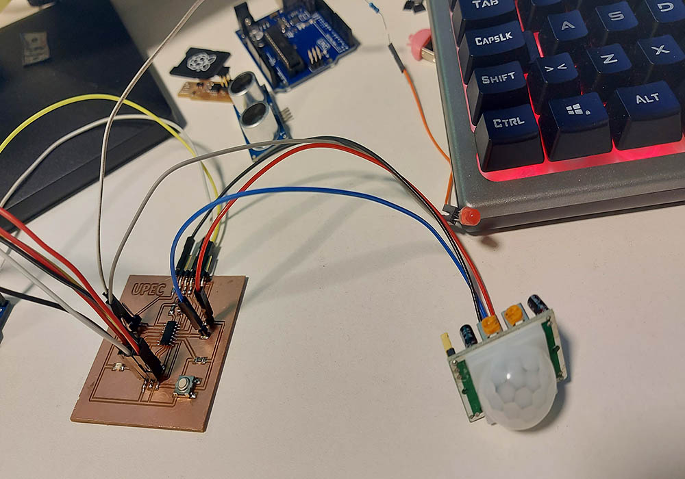
Now to be able to see the operation and to be able to see the communication between the controller, the sensor and the signal sent, we connect an FTDI module to our controller, this is connected to the rx tx pins of the pcb board, and we use a proto board to gnd and vcc connections
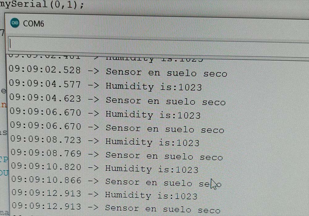
During the process of programming the board, I found it difficult to send a message to the pc using the serial monitor.
This week's work was quite interesting and opened the doors to new ideas and design possibilities that I had not explored before, there is a lot to learn in design tools, but expertise is not learned overnight.
Finally, you have to remember all the safety parameters to make good use of the machines, especially the laser cutter, which can be very dangerous. When it comes to cutting vinyl, it was a lot of fun to be able to make custom stickers, although the job of removing excess material is a bit stressful