Assignment:
Group Assignment:
1# Compare the performance and development workflows for other architectures.
Individual Assignment:
1# Read a microcontroller data sheet.
2# Program your board to do something, with as many different programming languages and programming environments as possible.
Brainstorm
Languages:
 3. Arduino - a really good language making for coding microcontrollers really easy.
 4. C# - a really powerful and efficient object oriented programmable language that allows lots of specification for game developpers.
Softwares:
Arduino - it is a great IDE that allows you to compile and upload your program's to different range of microcontrollers.
 Visual Studio Code - it is my main IDE. I love to use Visual Studio Code for almost any language because with tons of available free extentions to it you can use it in any type you want.
 Clion - It is a really good and powerful IDE for c++. It is specially created for coding in C++, hence, it brings lots of features to c++ that other IDEs do not have.
Machines:
 Macbook Air - This is a perfect computer programming. It is slick, easy to carry around and powerful.
Group Assignemnt
For this week group assignment we have cheked the performance and the development of different programming architectures. We have created a Google Spreadsheet with some basic information on different types of microcontrollers. You can access that spreadsheet by clicking here. Moreover, for our group project we all have programmed at least 2 different micro controller from different families.
Moreover, while preparing the spreadsheet we gave researched the board name, the family name, Bus Width, Clock Speed, Memory, Number of Pins, Logic Level Voltage, Package Style, and some links for the Pin out diagram and the data sheet for the micro controller. I have collected the data for ATtiny1616-SNR using this data sheet. And for Teensy 4.0 the data sheet is here.
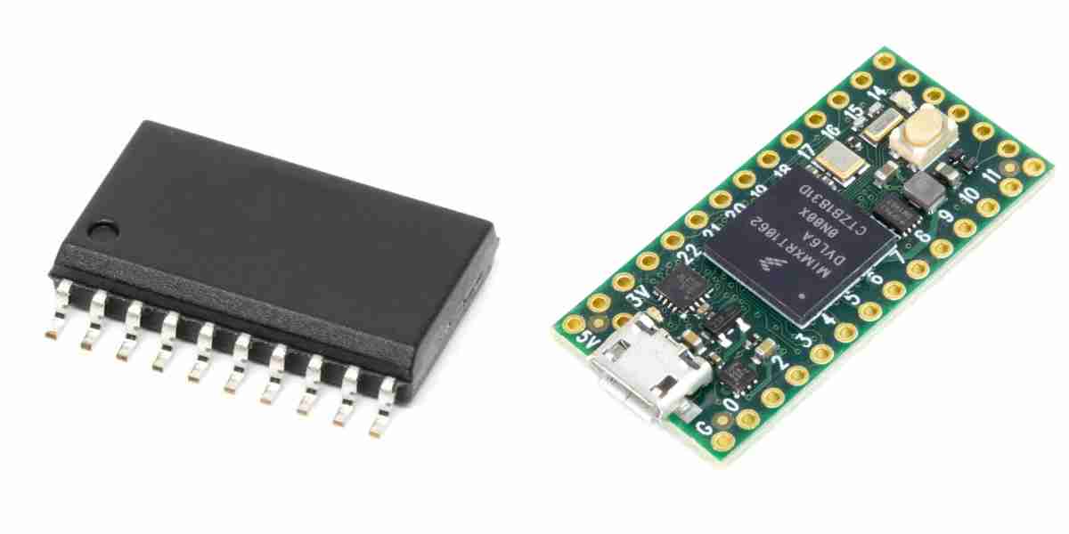
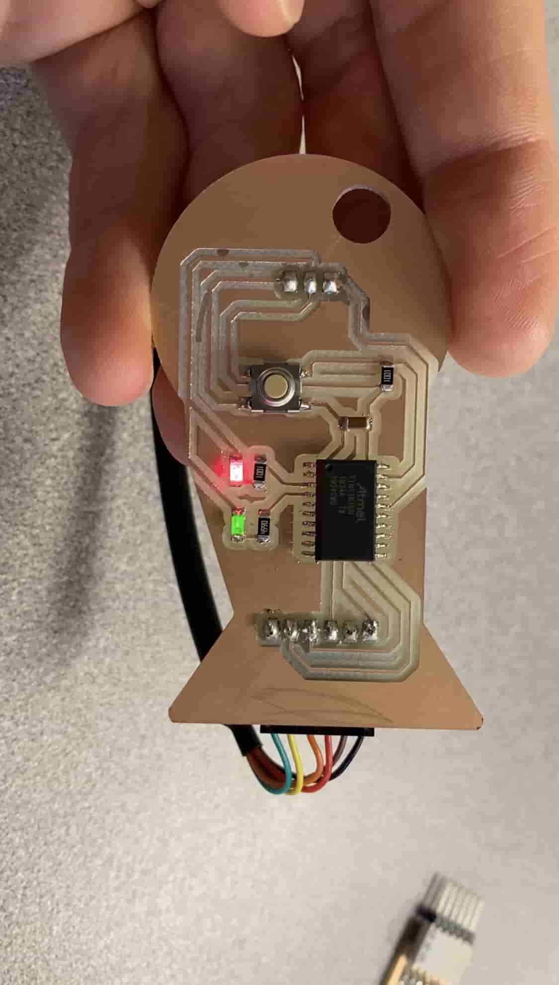
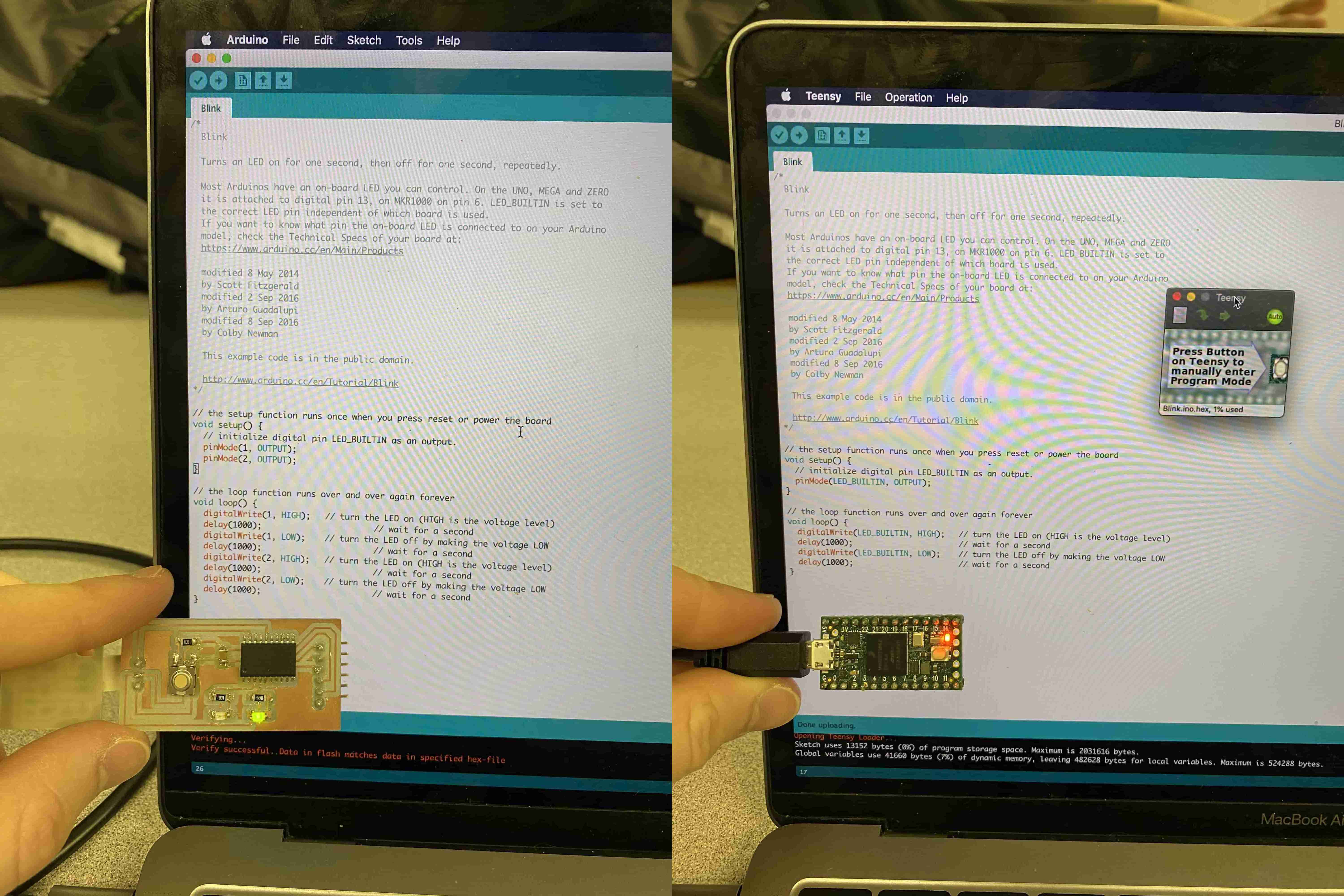
I have programmed ATtiny1616 and Teensy 4.0. For programming them I used Blink script. Blink script is an Arduino built-in example that just turns on and off the built-in LED. In my case Teensy 4.0 had a built in LED but ATtiny1616 did not so I had to change to code just a bit to refer to the pin connected to the LED. After downloading the board software information to Arduino I was able to select the board I am programming from ARduino Tool selectin and upload my code to it. After uploading, I was able to turn on the LED's on both of them. I have learned that Arduino is not only a language but an IDE and also it's own microcontroller. I learned that Arduino is a great software for combining programming for almost all the microcontroller's programming to one place and centralizing it.
I learned that some boards and microchips comes with built-in LEDs and manufacture Datasheets. Because the board with ATtiny1616-SNR microcontroller was made by my professor, there was no manufacturer's data sheet. Hence I needed to figure out which pin I need to use for the Blink
Later, we recoded the Blink script to remove the delay between turning on and off the LEDs. After doing this, the built-in LED on boards seemeed like they were always on but just a bit dimmer. After using an ossciloscope we understood why. WE also understood the meaning of clock speed.
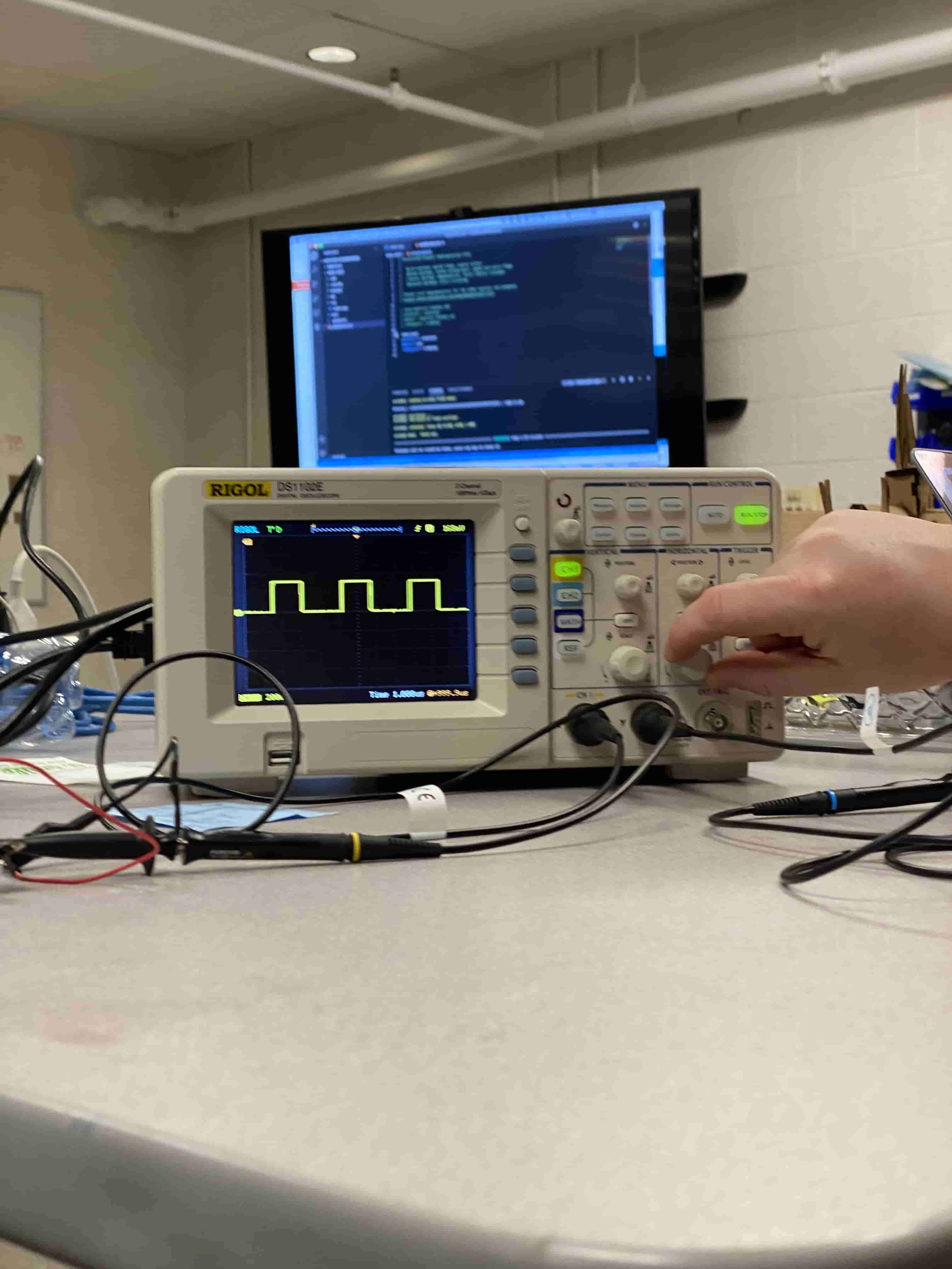
When we connected the Oscilloscope to the GND and the LED pin of the Teensy 4.0 we saw that the Teensy was actually sending ones and zeros but it is soo fast that the human eye was not catching it. The frequency of turning off and on was around the clock speed of the micro controller explaining the importance of the clock speed.
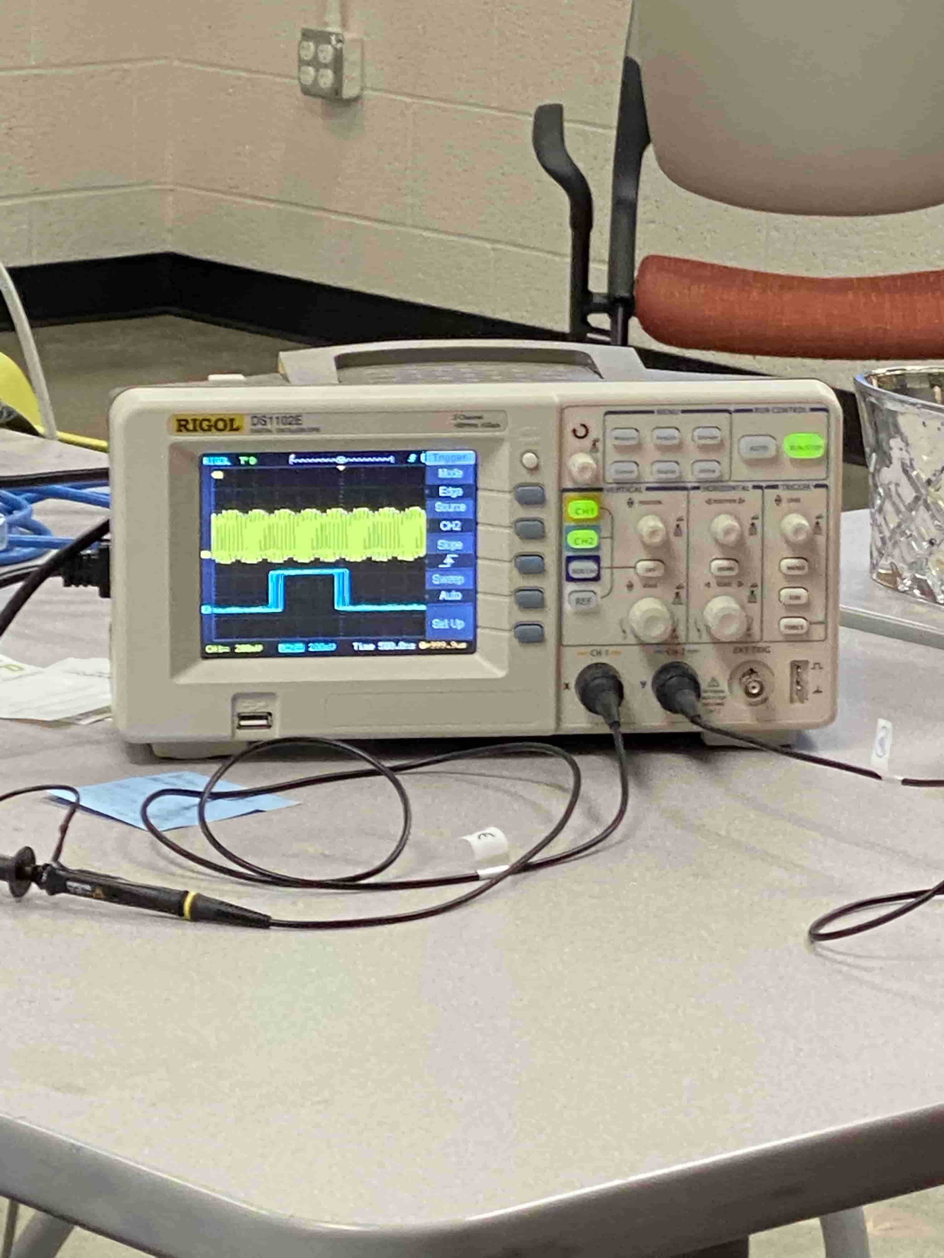
Then we connected two different microcontrollers at the same time. They had a difference in their clock speed, Hence from the previous outcome it was expected that the second one (blue) would have a smaller frequency of ones and zeros. When we connected them to the oscilloscope we saw that Blue one (second microcontroller) was way slower than the other one. This is why clock speed is important. Of course when you are trying to turn on and off an LED it is not that important because human eye cannot detect it but if you were to send a really large file back and forward you would want it to be fast.
Individual Assignment
Reading a Microcontroller Datasheet
I have used ATtiny1616 on my board and using this graph was really helpful on which FTDI connections should connect to which pins on the microcontroller. In the picture above we see the ATtiny1616 pinout layout.
On the top left corner we have the Legend (map key) of the map. Just on the right of it we see some extra stuff that is actually important. In microcontrollers or other types of controllers there are usually analog and digital pins. The difference between them that Analog can only input or output 5V at a time while digital pins can read or output varying voltages and this is called Pulse-width modulation. ASYNC INTERRUPT is a clock mechanism in the microcontroller that allows the microcontroller to stay in the same time as the real world around it and it achieves that through using it's specific pins to talk to outside world. CPU clocks are important in day/night cyles in games or creating counters etc. Moreover the last thing next to the Legend is lternative locations of specific pins.
The ATTiny1616 Pins are consisted of
- pin #1: VCC - This is the pin for powering the microcontroller.
- pin #2: PA4 - This is a SS pin that allows communication with peripheral devices/components that require SPI (Serial Peripheral Interface)
- pin #3: PA5 - This is a VREF pin that configures the reference voltage used for analog input
- pin #4: PA6 - This is a DAC pin allows you to translate numeric values (digital) to analog signals
- pin #5: PA7 - This is a digital pin
- pin #6: PB5 - This is a normal programmable pin that reads 5V or outputs 5V
- pin #7: PB4 - This is the alternative pin to pin #2 for being a digital pin
- pin #8: PB3 - This is a RXD pin which is used for retrieving data from the computer, talking with the computer
- pin #9: PB2 - This is a TXD pin which is used for sending data to the computer, talking with the computer
- pin #10: PB1 - This is a SDA pin. Which means it has it's own resistor that acts as a pull-up resistor
- pin #11: PB0 - This is a SCL pin. SCL is the clock line. It is used to synchronize all data transfers over the I2C bus.
- pin #12: PC0 - This is a SCK pin which is used for serial clock output.
- pin #13: PC1 - This is a MISO (Master In Slave Out) pin which is the Slave line for sending data to the master.
- pin #14: PC2 - This is a MOSI (Master Out Slave In) pin which is the Master line for sending data to the peripherals.
- pin #15: PC3 - This is the alternative pin for SS pin
- pin #16: PA0 - This is the UPDI pin which is used for reseting/programming/editing your microcontroller
- pin #17: PA1 - This is the alternative pin for MOSI, TXD and SDA
- pin #18: PA2 - This is the alternative pin for MISO, RXD and SCL
- pin #19: PA3 - This is the alternative pin for SCK
- pin #20: GND - This is the pin for ground
However, next to each pin there are numbers in either orange or blue boxes. They represent the pin ID. We use the pin ID for coding. Hence, if you were to use pin #15 as your pin to turn on the LED on your board in your code you will reference it as pin 13.
For more info:
- SPI (Serial Peripheral Interface)
- MOSI - Master Output, Slave Input (Output from Master)
- MISO - Master Input, Slave Output (Output from Slave)
- SCK - Serial Clock: How it keeps time (How accuarate?)
- ADC - Analog to Digital converter
- AREF - Voltage reference that the chip will use to know the range of Voltage.
- PDIP - Dual-In Package (Though hole)
- SOIC - Small Outline Integrated Circuit.(SMD - Surface Mount)
- EEPROM - Electrically Erasable Programmable Read Only Memory. Memory to keep its value after the power is removed (stores setting)
- PWM - Pulse Width Modulation : a method of reducing the average power from electric signal by chopping them up. It turns switch between supply and load on and off at extremely fast speed.
- Peripherals (Hardware Input/Output Device)
- Ports (pins) - Datasheet IO (input/output) parts.
- A/D - Analog to Digital
Programming my Board
In week7 I have milled and created my own board. However, I did not oceded it using my own program instead I programmed it using an echo hello program. In this week's assignment I will be creating a program that takes in an input from the user and then prints out the message in binary using the two LEDs on the board. For this I have decided to use ARduino IDE and language at first and then use other IDEs and languages to code the same thing.
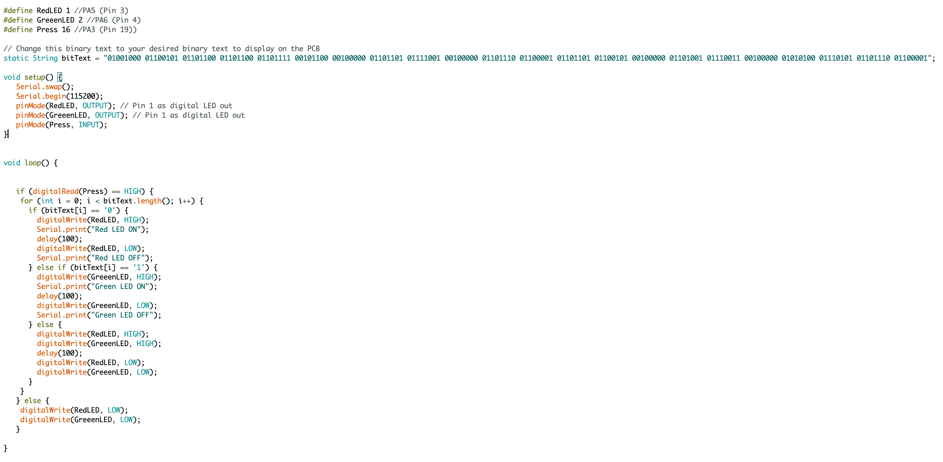
In this code at the top I am defining some variable that will be the Pin locations for the LEDs and the Buttons. Than I am creating a string variable called bitText which represent the text I wan't to display in binary mode. To change this just go to Text to Binary Converter. Then copy paste the binary code to the binText variable. "Void Setup()" is the first function run when the microcontroller starts. In this function we have "Serial.Swap()" This helps me swap the RTX TXD pins to their alternative locations. This is because while designing my board the week before last week I have accidentally connected the TXD and RXD from the FDTI cable to the alternative pins on the ATtiny1616 microcontroller. Then we have "Serial.begin(115200)" This starts the Serial Monitor or in other words starts the communicitation between the microcontroller and the computer at 115200 bauds. The next Three lines I define the pins as either input or output. Or in other words, I am telling the microcontroller which pin to look out for and which pin to give 5V to. I need to do this so I can say turn on that pin and the microcontroller will know that that pin is an output pin and won't confuse it with "read HIGH on that pin." The second function is the "void Loop()" is the function that loops continuously. In this fucntion you write stuff that you want to continue non-stop. For example in my case I want the microcontroller to check if the button is pressed or not. The speed or the frequency of void loop function repeating is corelated to the clock speed of the microcontroller as we observed from the group assignment part. And in the if and else statement for the button, I have for loop that goes through each letter in bitText. Later, in the if and else statement in for loop, I check if it's zero or one in bitText and according to that I either turn on or off the green or red LED for 0.1 sec.
Programming in different IDEs and languages
Instead of writing different code for each IDE, I have decided to use the same code I have writed. I already used the language Arduino and Arduino IDE, Hence, I will be using Visual Studio Code for writing it in C and C# and Python, and I will be using CLion to write it in C++. Normally neither Visual Studio Code not CLion can export the code to the microcontroller, however, Visual Studio Code has an extention to it called PlatformIO that allows you to create a project for a specific device and export it to the microcontroller.
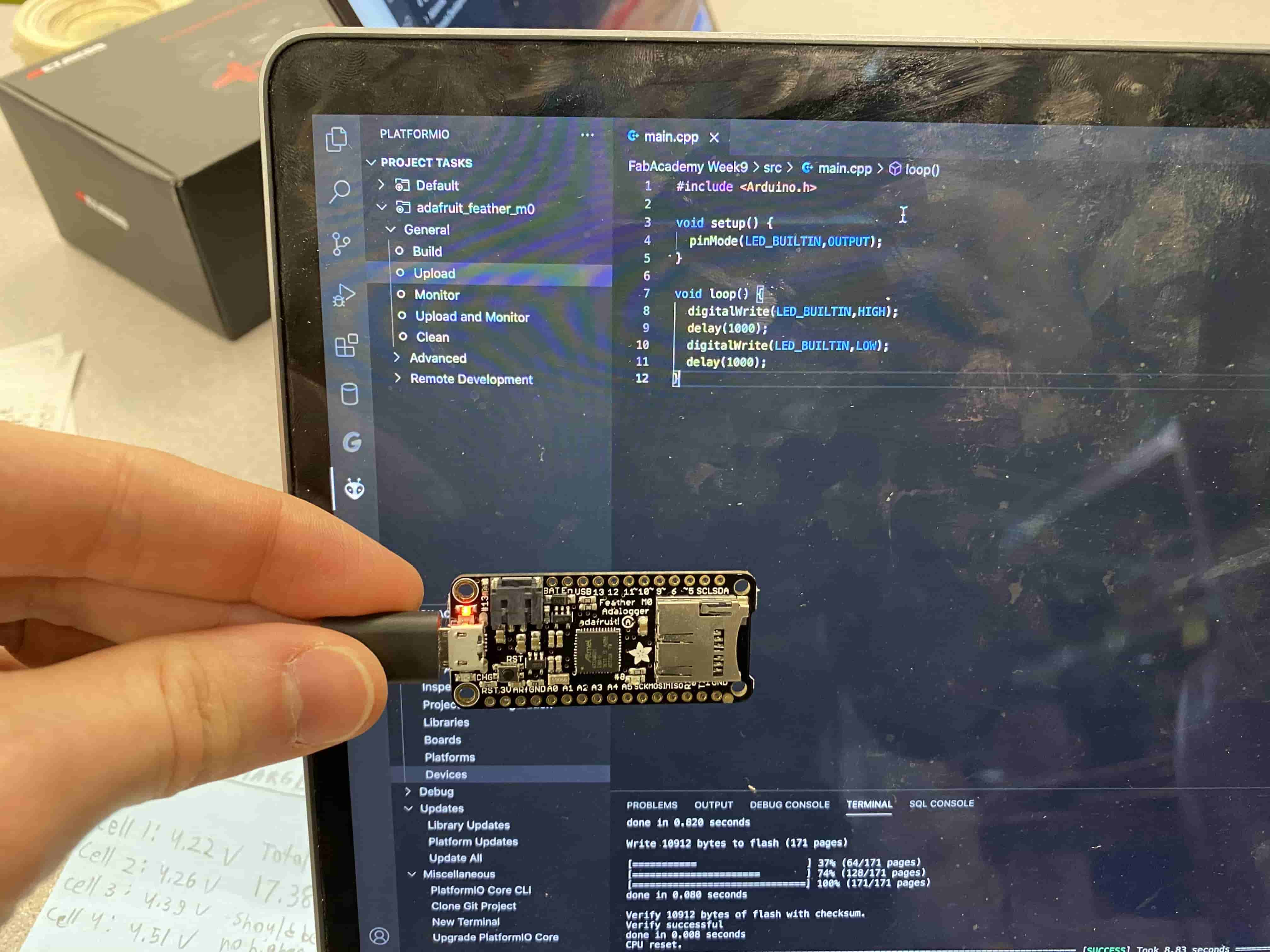
In the example below, I am using a feather microcontroller to upload Blink script on using Visual Studio Code with PlatformIO and Arduino Language.
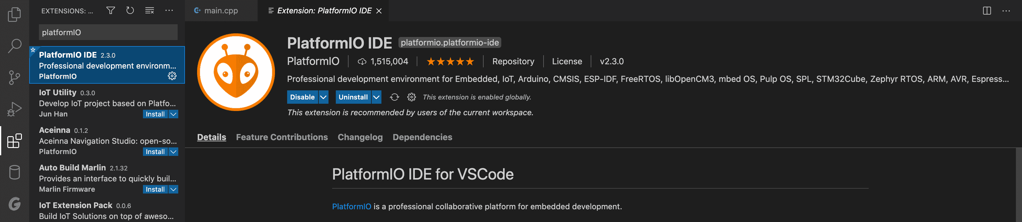
Initially I went to the extentions tab in Visual Studio Code and Searched for PlatformIO IDE.
After downloading the PlatformIO IDE extentions, the alien icon should appear in the left side of the VS Code. if you click at it, you will see Quick Access menu come out and click on open which then will take you to the Home page for PlatformIO IDE. At here you can create new projects.
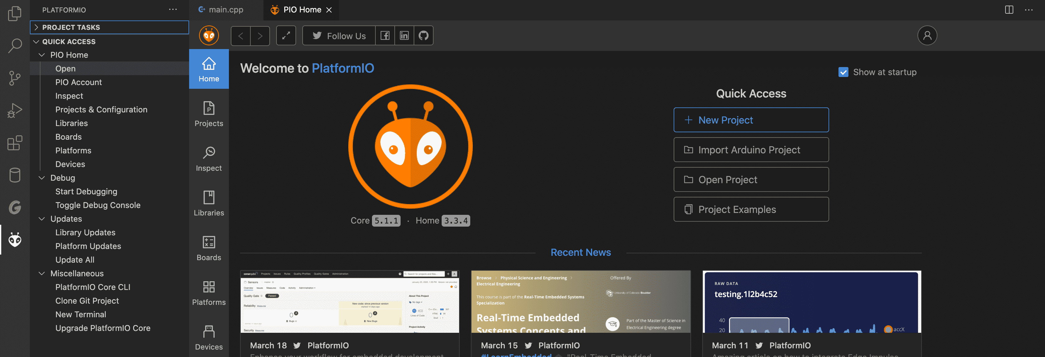
After clicking install, it took a while to install. I think it was the longest time taking extention I have ever downloaded. This is because PlatformIO is like a completely different IDE in Visual Studio Code. However, because it still depends on libraries on Visual Studio Code it is really small compared to other IDEs at the same time which makes it really efficent. I have created one for ATtiny1616 by clicking New Project Button:
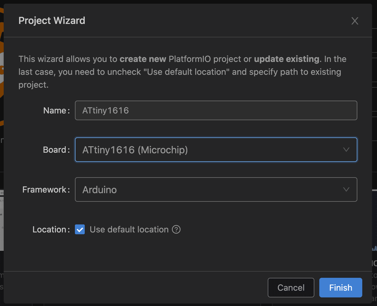
Once I clicked at the "New Project" button, I am greeted with the Project Wizard. At there I create a project name and then select the device I want to program for. The list of devices you can select is really vast. I type in ATtiny1616 and select the one I want. Then it automatically selects the framework you want. I also clicked at the framework to change it to a different language but no avail nly Arduino is available. Then I have clicked Finish and it started initializing.
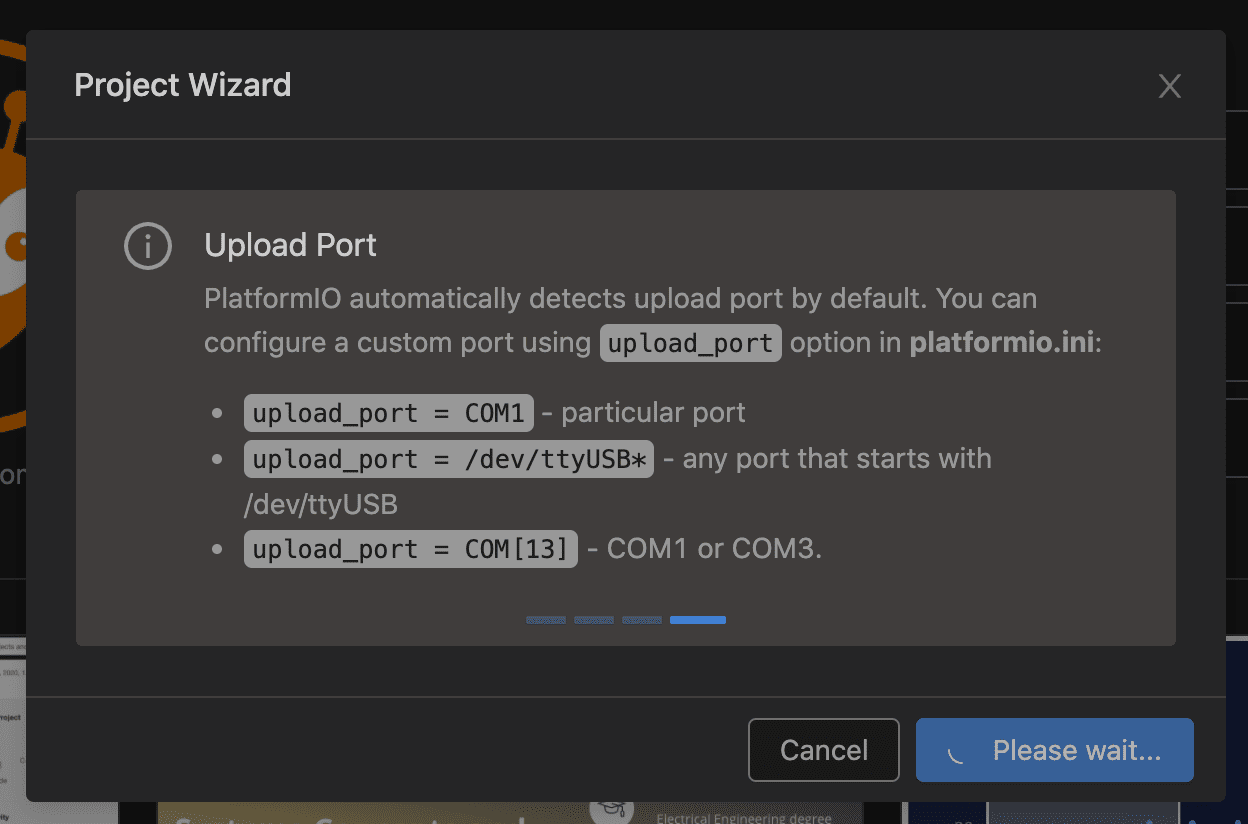
Creating the project takes around 3 to 5 minutes. compared to Arduino IDE it takes so much time but unlike Arduino IDE because you creatthe project specifically for A board, you don't need to do all those tool setup, library setup, preferences setup, etc.
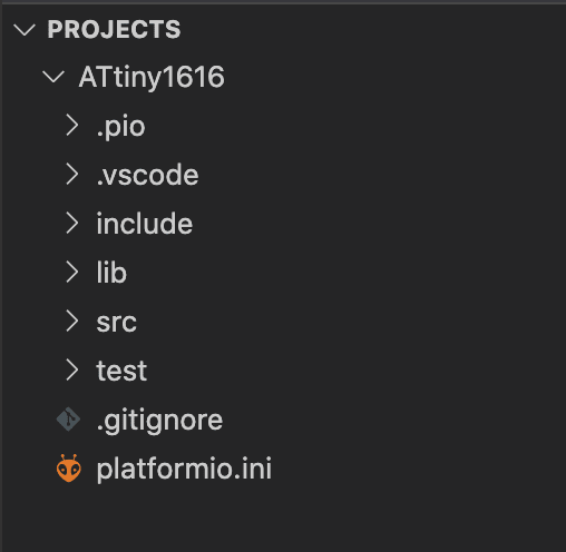
Once you have created your project on the left hand side you get this project menu in which yu can see different folders. For the time being I will be only concerning with only the src folder because that's the folder where is the arduino file is. However, it is actually not an arduino file or in other words an .ino file but it is actually an c++ file (.cpp) This is because Arduino is another variant of C language and in our case we turn c++ to arduino by adding the arduino library.
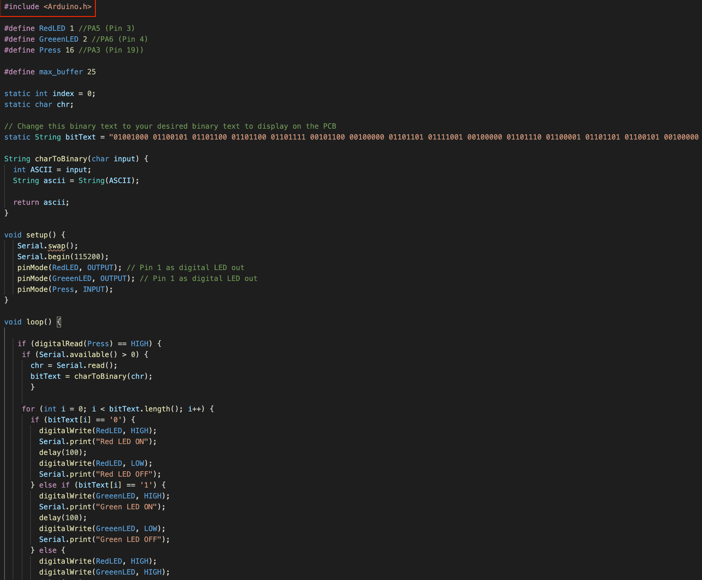
As you can see, the first line of the code is "#include <Arduino.h>" that line represent to importing the Arduino library to our code so we can use stuff such as void setup() or void loop() or #Define etc.
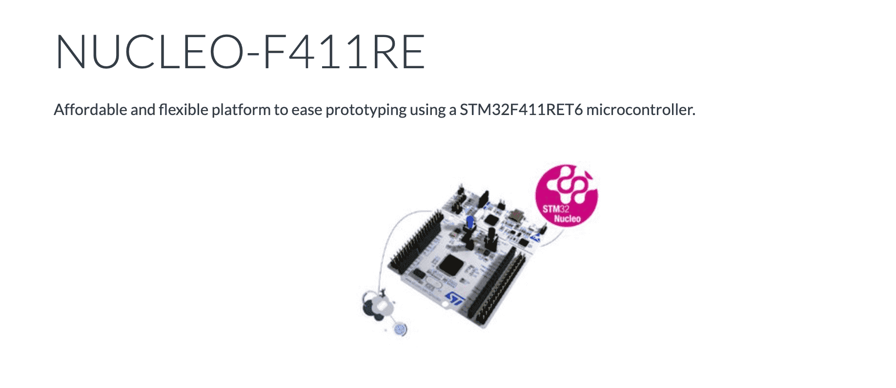
For second method of programming I still have used Visual Studio Code but this time with mbed IDE. As tutorial I have used mBed Tutorial by Bme Builds. I went to google and made an account at mbed compiler. At here they create quick debug files for specific boards. Unfortunately there wasn't one for ATtiny1616 Hence, I had t select the most similar one which happens to be NUCLEO-F411RE.
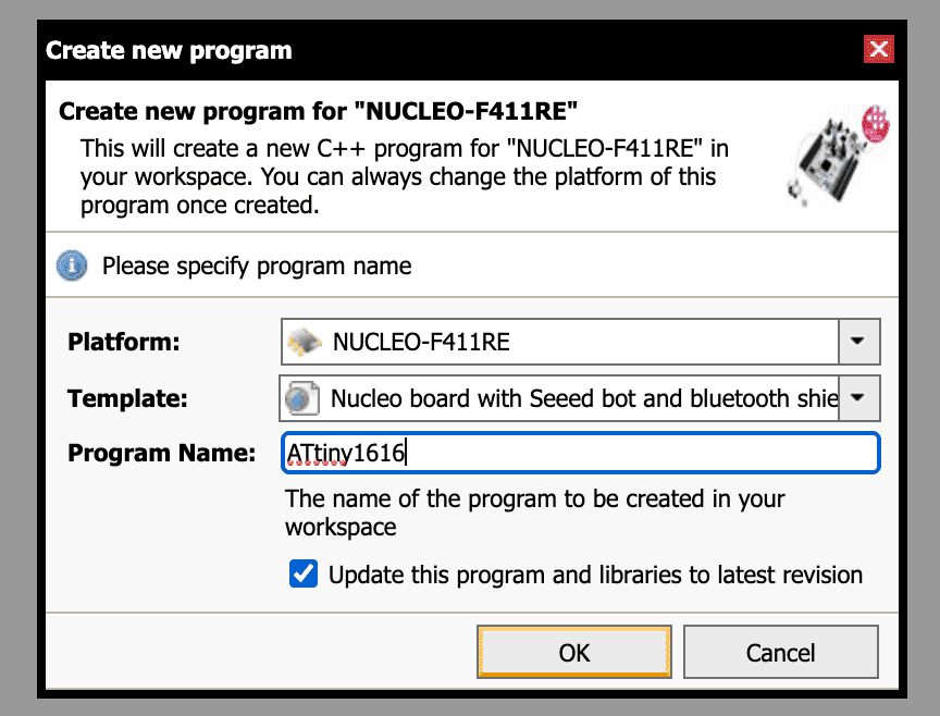
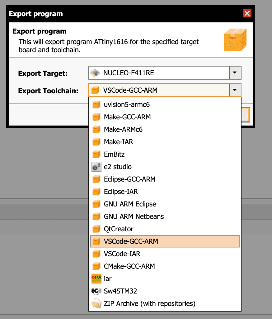
After knowing what to select, I went to mbed and created a new project and selected NUCLEO-F411RE as programee. I clicked at "NEW" on the top left corner and selected the programee and the name of the project
It takes few seconds to create a project, then you can right click at ATtiny1616 project we just created and click export and select VSCode-GCC-ARM and then click export.
After exporting it as a zip file I was able to unzip it and open the folder using VSCode. After opening it I deleted some unnecessary files and changed the code to fit my desire or in other words just turning off and on a LED.
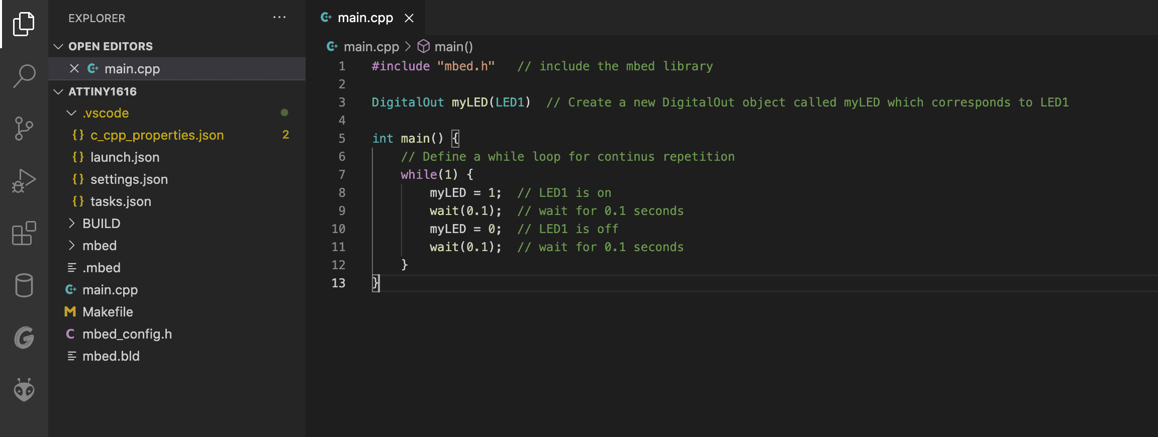
After writing your code do command+shift+B to compile your code and then go to the debugger tab and run the Build files while your ATtiny is connected to your computer. Unfortunately, I was not able to compile it to an actual Attiny. I think the reason to this is because the initial place (mbed IDE) does not actually support ATtiny1616. So I actually had to create a pseudo ATtiny1616. Even though it did compile, it was having problems with recognizing the microcontroller and did not upload.

When I tried using mbed I was not able to find the desktop IDE, so I have used the online version of it. So as I showed in above steps I had to create a pseudo ATtiny using one of their own boards as a base and I downloaded the library above to maybe make it work since, it says that it includes the libraries for the ATtiny. Again, when I tried to upload it, it did not even compile this time due to the new library I was triying to add. Maybe next time if I try mbed's new Desktop IDE, I can make it work. Because I feel like all that creating a pseudo ATtiny1616 and then exporting the whole thing to Visual Studio Code, caused so many errors that it broke the configuration.
After rewatching the tutorial I have used for mbed IDE. I have realised that the video was for ARM microcontrollers and not for AVR microcontrollers. This is definetly the main problem why it did not work because ATtiny1616 is an AVR microcontroller.
We have done Tinsy as our group assignment so I did not wanted to redo that since I already know that it works and I already explored that, we also did Platform IO. That's why I wanted to try Embeded Python but again I was not able to push it to my board because even though I was able to find an online simulator I was not able to find a downloadable compiler/flasher for embeded python for ATtiny series. Fortunately, I was able to make a simulated board with a microcontroller work using Embedded Python.
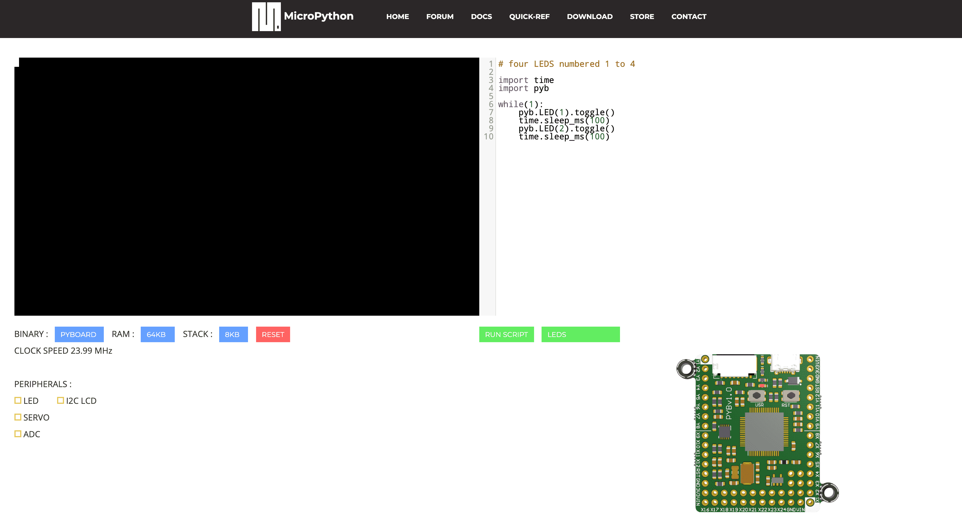
Python is a really powerful and easy to use tool however, because of it's inefficiency almost no one uses it for embedded programming. However, there are parts that Python wins, for example AI or complex computation. I wanted to learn how to do embedded Python programming so as first step I went online and searched if it is even possible and I found out that it is but it is really impractical. However, I still wanted to work on it. I was not able to find an IDE that I can download to my computer and use but I was able to find an online IDE called MicroPython
If you want to see how to successfuly upload codes to your board you can visit week 7 - Electronics Design or week 13 - Networking and Communications or if you want to learn how to upload a code that will react with an application in your computer check out week 14 - Interface and Application Programming.