Assignment:
Group Assignment:
1# Review the safety data sheets for each of your molding and casting materials, then make and compare test casts with each of them.
Individual Assignment:
1# Design a 3D mould around the stock and tooling that you’ll be using, machine it, and use it to cast parts from it.
Brainstorm
Softwares:
 Arduino - it is a great IDE that allows you to compile and upload your program's to different range of microcontrollers.
 - Fusion 360 - A CAD software that allows both 3D and 2D designing
- Vpanel - A CAM software that talks with Roland SRM-20 Desktop mill to send the job
- Fusion 360 - A CAD software that allows both 3D and 2D designing
- Vpanel - A CAM software that talks with Roland SRM-20 Desktop mill to send the job
Machines:
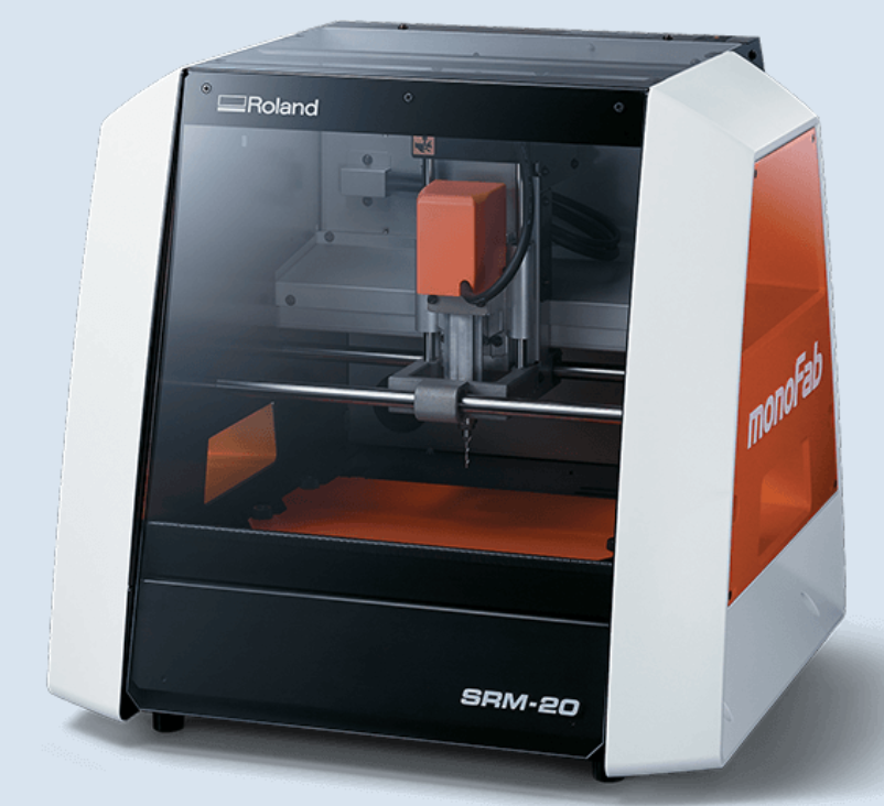 Roland SRM-20 - it is a precision mill that can hold variaty of small endmills ranging from 0.3mm to 6mmm diameter endmills
Group Assignemnt
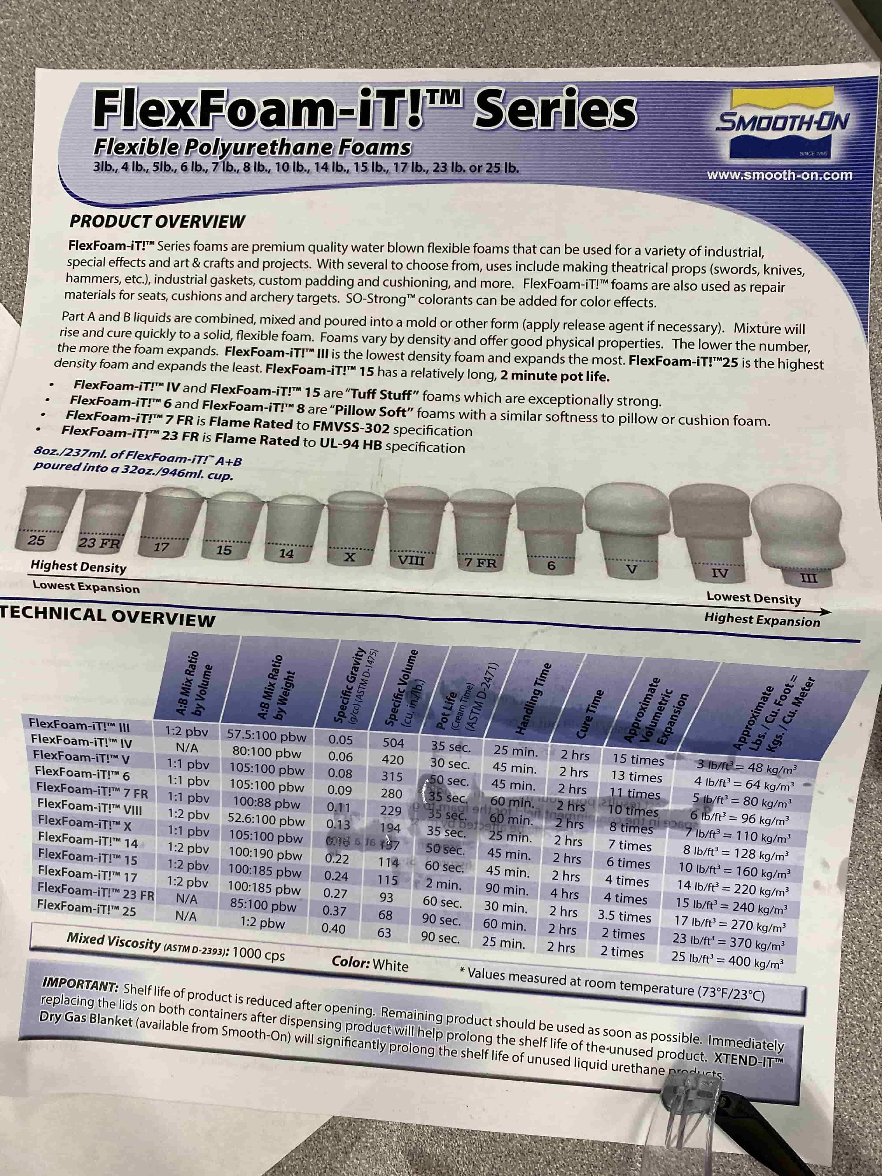
For the group assignments we have looked through different materials and learned how to use them and the safety procedure. Initially, we worked on a foamy mixture. for this we used "Flex Foam-iT III."
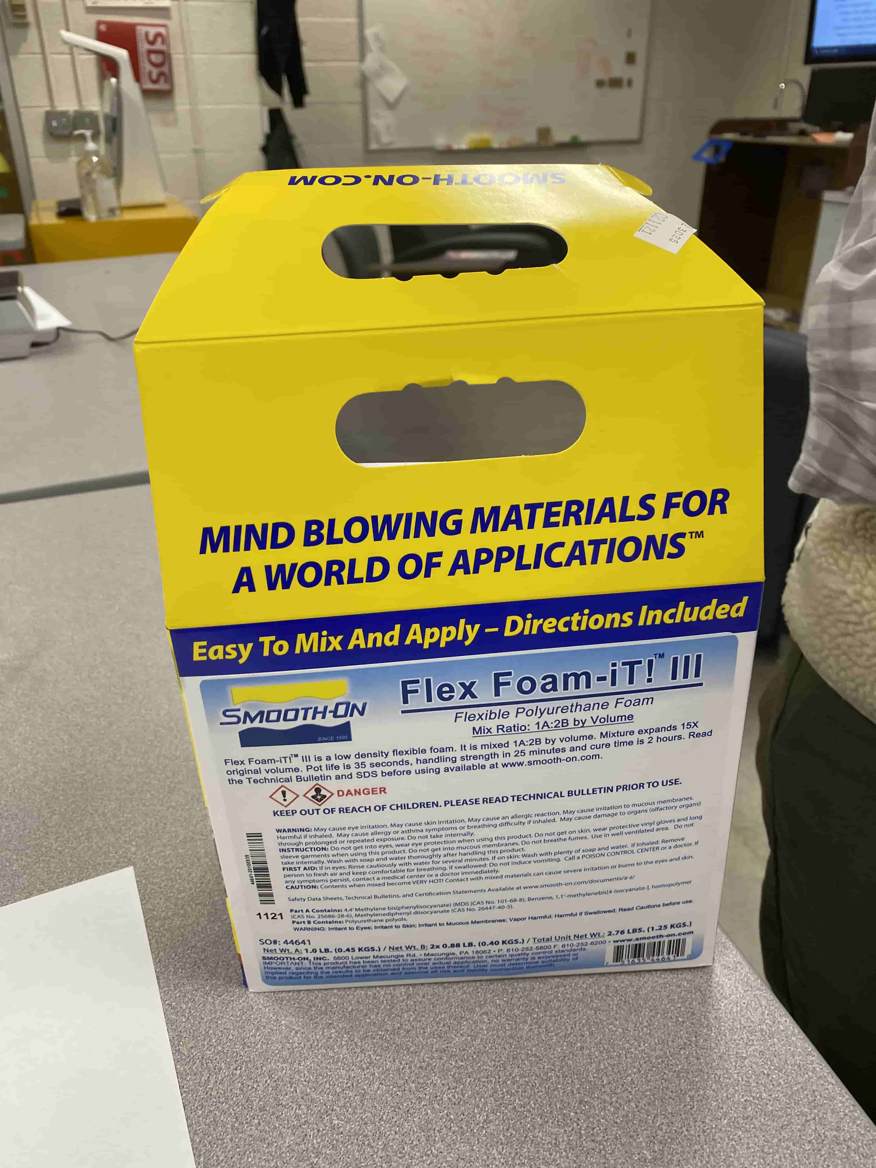
However, before using it we need to read the instruction sheet. We learned that some of the of the materials for Mold making can be corosive and toxic. We also learned new stuff like by Volume ratio or by weight ratio, handling time, cure time. By volume ratio is how much of the two liquids in ml you need to mix to have the foam and by weight ratio is how much of the two liquids in grams you need to mix to have the foam. Handling time is the time that takes to solidfy or slow down in curing process where yu can finally take it out of the mold. Curing time is the time it akes for it to fully cure and solidfy and no reaction occurs anymore.
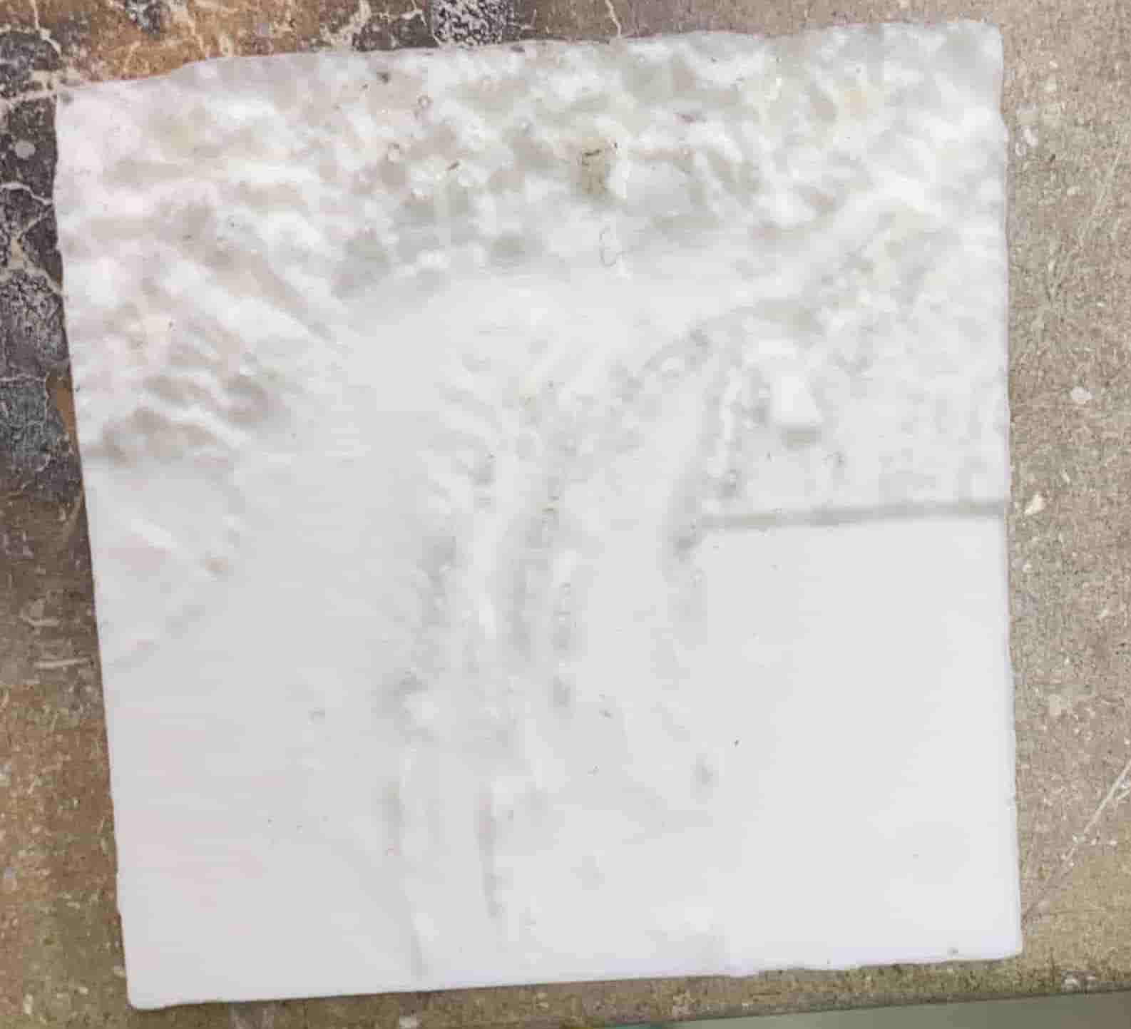
After reading the foam mold instructions, we have poured it into the mold and put a lit on it with a hole. Because in the instruction sheet it was saying that it grows 15x bigger while curing, Hence, to keep the same shape while allowing it to expand, we have used an acrylic panel with a hole on it.
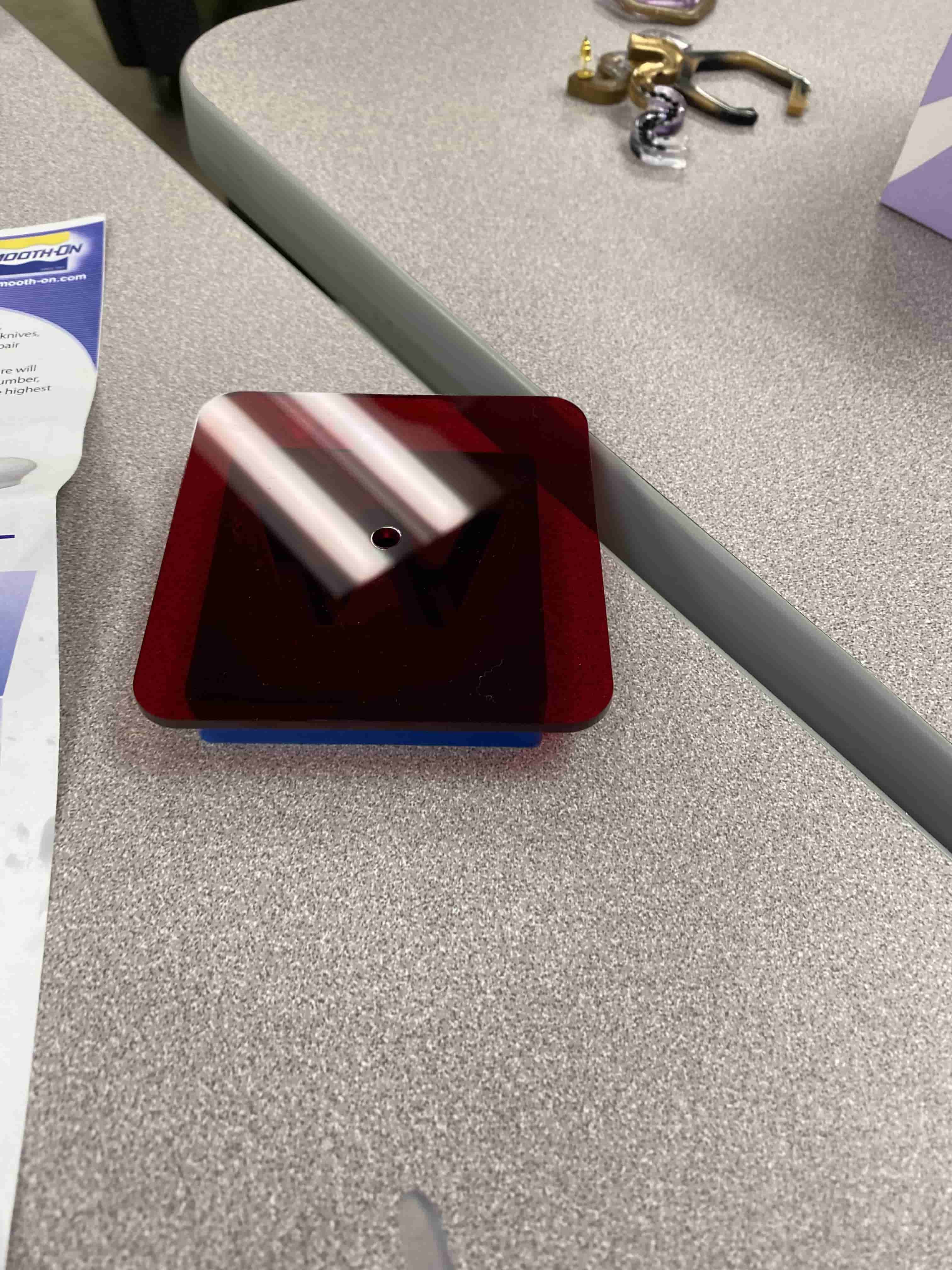
and this is the image of foam mold after curing:
We also worked on identifying the important variables for each of the molding and casting mixs we have. we have identified variables such as the safety, the mixing ratio (by volume and/or weight), how to mix, pot life/handling time, release agent, cure time, Common Aplications, Shelf life and Pro tips.
I have attached the link to the google spreadsheet with all the information here
Individual Assignment
For my individual assignment, I decided to create a mold in the shape of Wheaton College MA's logo and use that as a mold for creating chocolates in the shape of Wheaton's logo. For this I have used machinable wax. One of the reasons why I chose to use machinable wax is because I am trying to make only a small mold hence I have really small details which can only be done in a precision mill. Thus this creates the problem of only being able to use really small endmills. Hence, I woudn't be able to carve copper or wood for 0.75 inch deep. So, I selected to use Machinable wax.

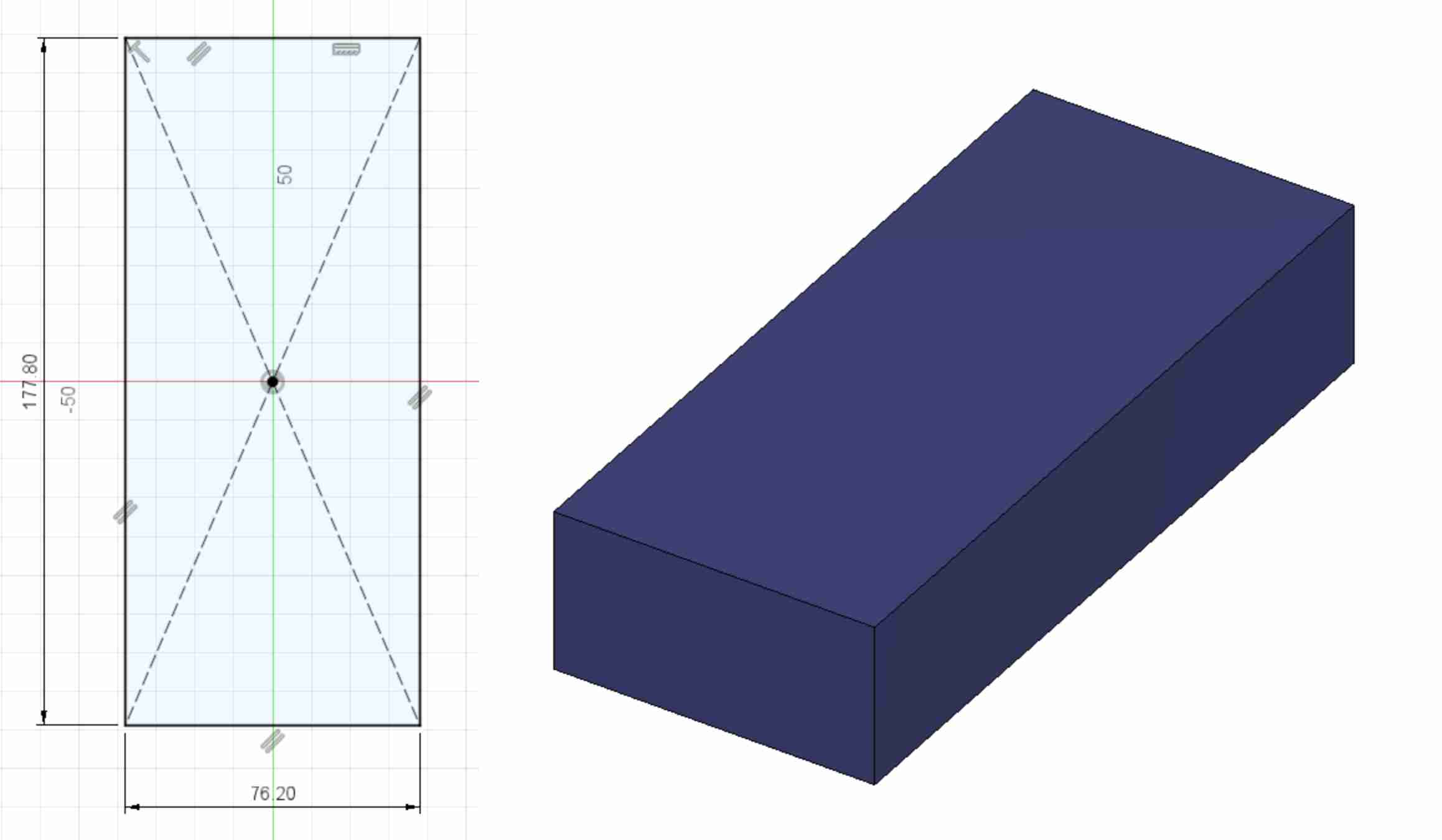
As first step I checked the dimentions of the Wax and recreated it on Fusion360. Because it was just a rectangle, it was really easy to recreat. The hard part was putting the shape on. At first I tried to do a Griffindor symbol from Harry Potter, however, it was too detailed that even 1/64 bit was not able to carve it out. Hence, I moved on to only making the Wheaton College's logo. Instead of creating the logo myself, I went online and downloaded the logo in jpg format then removed the background using an online resource linked here and then turn it into a black and white SVG using this website.


Now that I have the SVG version of my desired image, I can go to Fusion and first create a rectangle with the same size of my Machinable Wax.
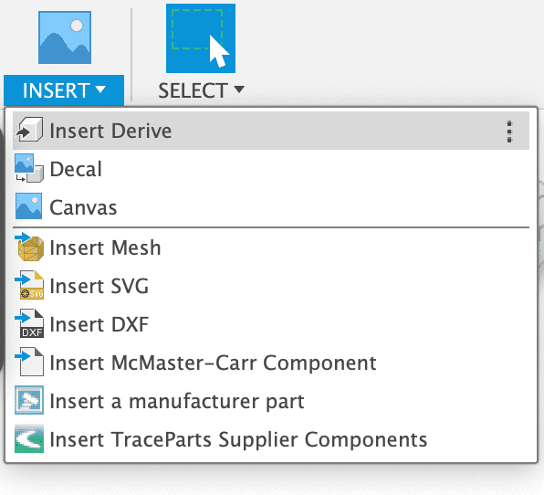
After recreating the Machinable Wax in the Fusion, Now I can create a new sketch on the top surface of it. The reason why I am doing it on the top surface is because I want the engrave the SVG image to the wax, hence, I start from the top. To import the SVG image I use the Insert Tool on Fusion and click insert SVG.
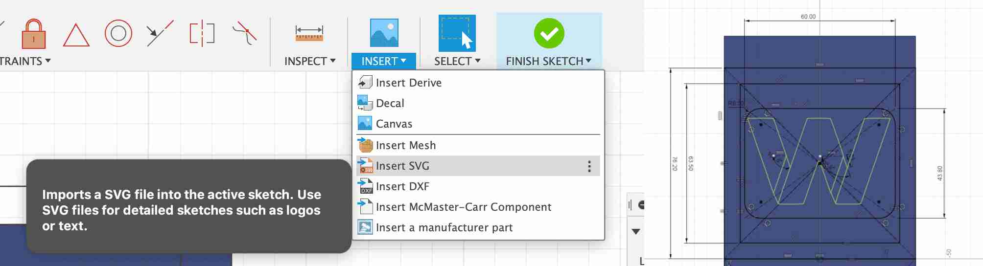
After importing it, it comes as a sketch that you can change it's scale and location and once you set it, it automatically locks itself down. So I had to be really precise while positioning it. That's why before positioning it I have created some construction lines that marks the center of the area I want to put my object to.
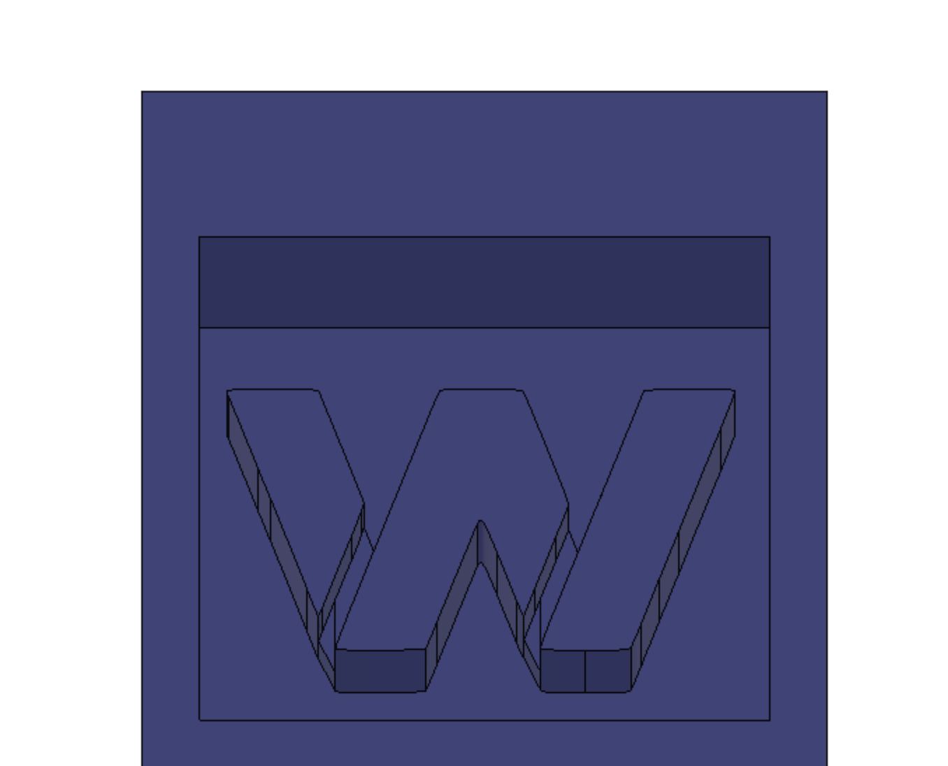
Now that I have my sketch done, I can extrude the parts that I want to be in chocolate and parts I want to be the mold. Currently I am using the machinable Wax as a mold for a mold that I will use it as a mold for chocolate.
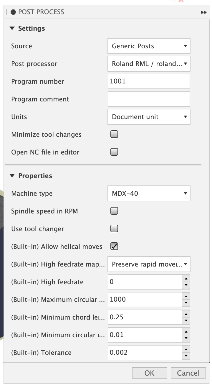
Now that I have created my object and also the engraving model I want, I can go to the manufacturing tab and create tool paths for it. In my first try after I created the tool paths andd set the origin and started cutting it on the Roland Precision mill, instead of cutting it at the left part of the Machinable wax it started cutting a really small version of it on the top left corner of it. Then I realized that this is because my axis signs are incorrect and the machine I selected in post processing has a different resolution than SRM 20.
Because I did not now how to interchange the y and x axis, I simply rotated my object by 90 degrees and then I have measured the distance from the origin point to the cut part and used linear algebra to find the multipliation of error and multiplied all my dimentions with that. However, simply I could have just do select Roland-RML MDX-40 for post processing and while seting up the origin point just align the X and Y axises according to lines oün my object.
As I earlier mentioned, I cannot use the Axiom CNC mill because my object is really small and detailed, hence, I need to use the Roland SRM-20 Precision mill. However, using endmills that are 1/32" in size would take hours to mill just that area. Fortunately we have a 6mm flat endmill and a 6mm collet. Hence I have created two different toolpaths one for 6mm and one for 1.2mm flat endmills.

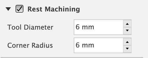
AFter selecting the regions and the right tools and the right origin point, Fusion 360 automatically calculated the toolpaths. However, because I am using the 6mm as a rouching pass, I don't need to remill out everything 6mm cut out already, so instead of that I can tell Fusion360 to only cut where 6mm couldn't to do this I can simply allow "Rest Machining" in toolpath edit and type 6mm for my previous tool.
After doing all this, the visualition of the toolpaths were like this:
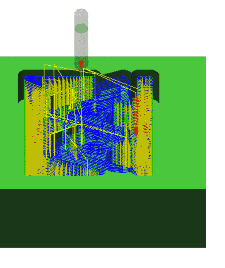
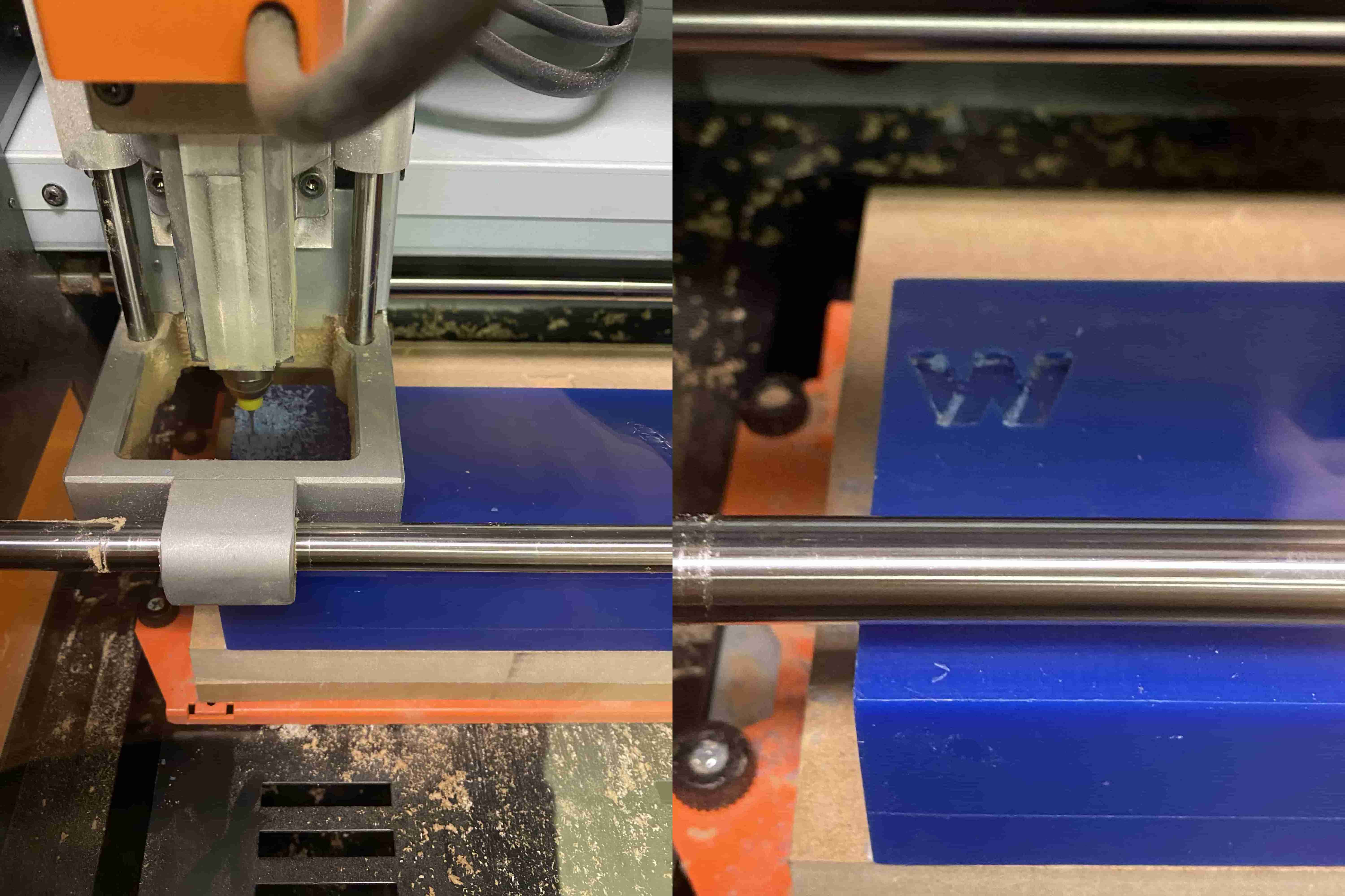
Now that everything is ready, I export it as RMD-10 Roland-RML (rather than RMD-40 because back then I didn't know that RMD-40 fixes the dimention issue). And placed my 6mm bit first and started my rouching pass with it.
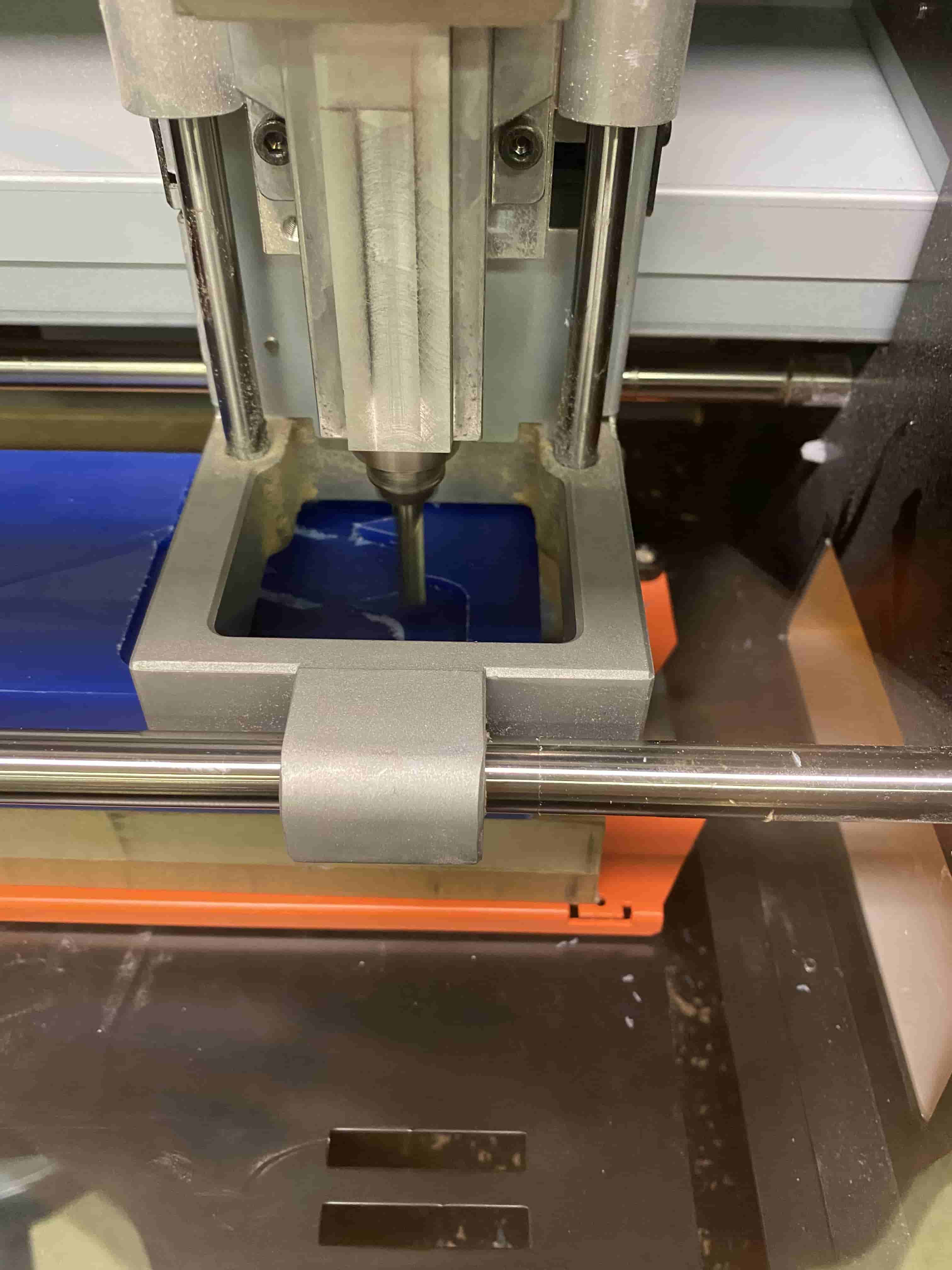
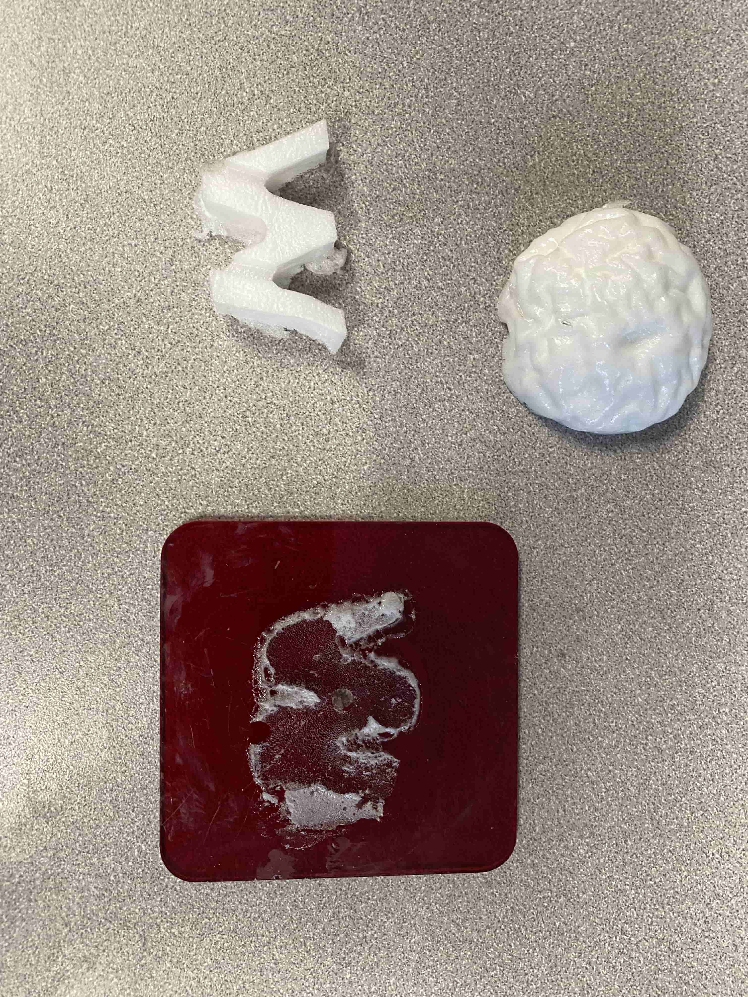
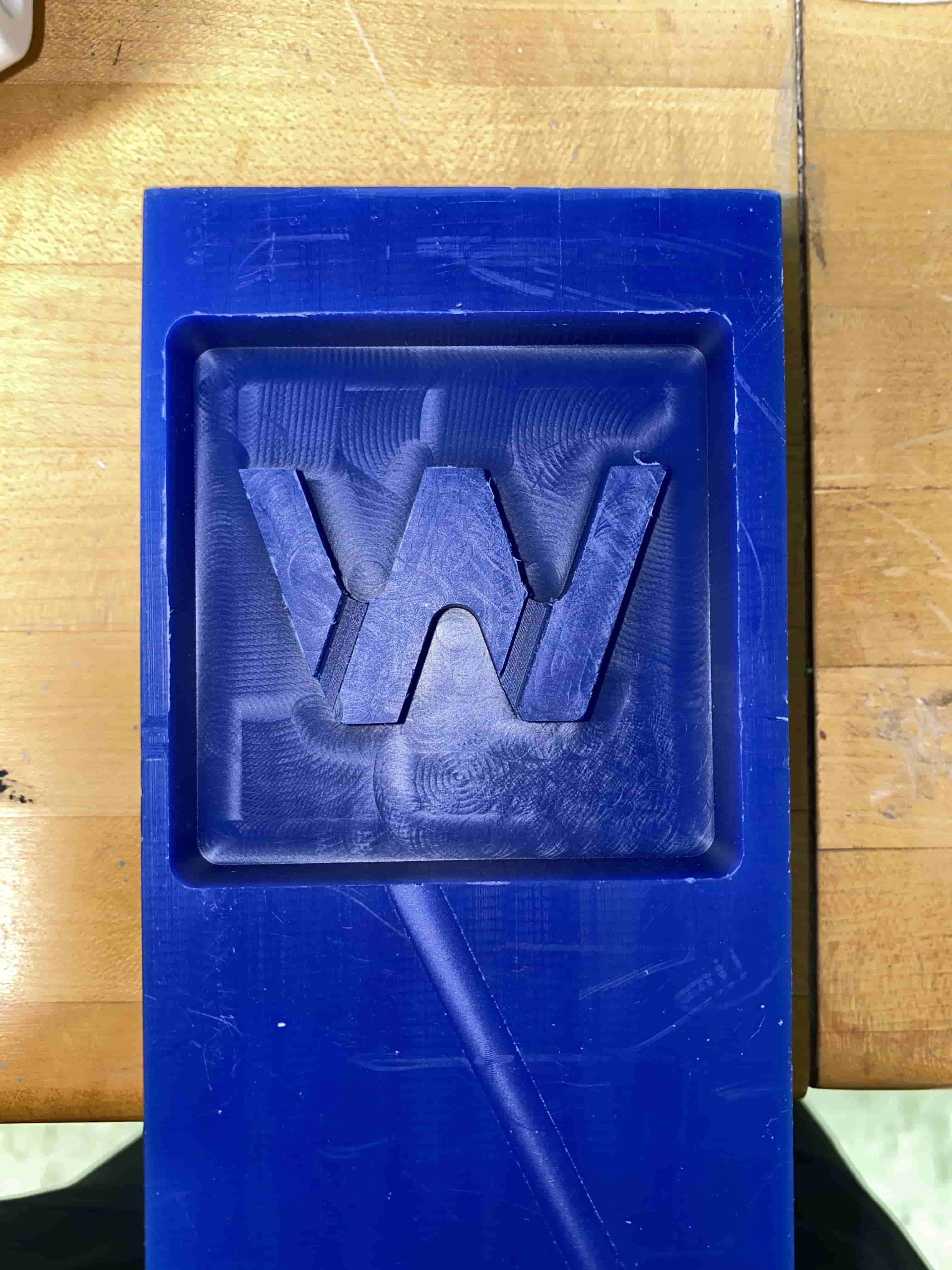
After everything Cut I removed the Machinable Wax and took a look at it.
Now that I have my finished Wax mold I can use it to create a second inverted mold. For this I have used blue resin that I filled it and put it in a Vacuum chamber.
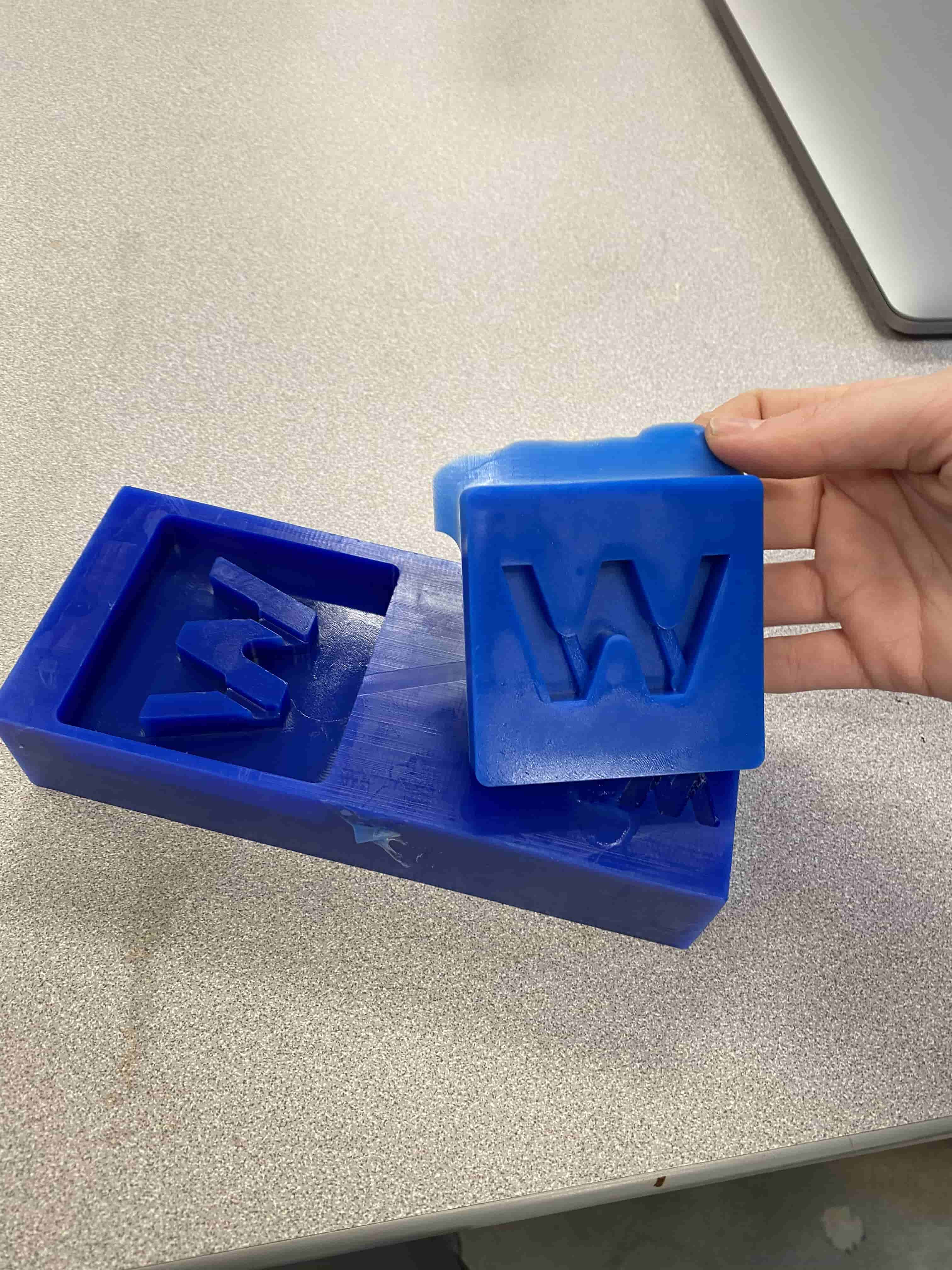
While it was in Vacuum Chamber, the Resin I filled it with started overflowing because my Wax engraving wasn't deep enough. So next time I do this, I will be making it overall 0.25 inch deeper.
Extra
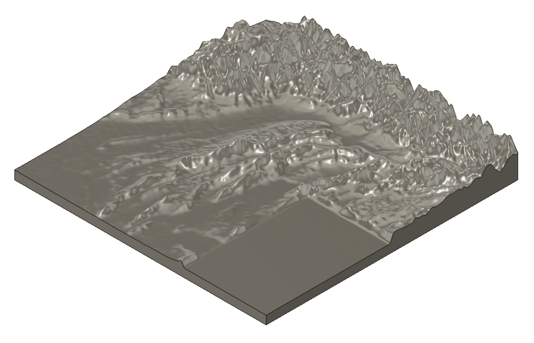
I have also created another mold with a topographical map on it. I have created this topographical 3D map last semester when I wanted to 3D print it. To produce this, I have went to the US geological survey world map and took topographical grayscale data. Unfortunately, they were in TIFF format and 16 bit rather than 8 bit which caused my computer to not be able to render it. So I used another software called "Graphic Coonverter 11" to convert all the images to png. After this conversion I was able to see the grayscale images. I then combined them using their metadata and their appearance and turned them into one big image. I then went to Blender and created a new surface which then I have divided into subsurfaces and loaded this grayscale height map to it. This created the map. However, to 3D print it or to convert it into a mold. I need to do some more changes. Currently it is only a surface and does require a base. For this I exported it as .obj and uploaded as Fusion. Unfortunatelly because it was too detailed my Fusion crashed and I had to deecrease the details. After I successfully uploaded it to Fusion. I have created a mesh out of it and convert that mesh to a body. Which then I made a square sketch at the same size just 1 cm below and extruded from that sketch to the surface which created the object. Afterwards, I have disabled all the other stuff other than the boody I have just created and export it as STL to 3D print. However, now that I am going to use it for molding, I need to do couple more steps.
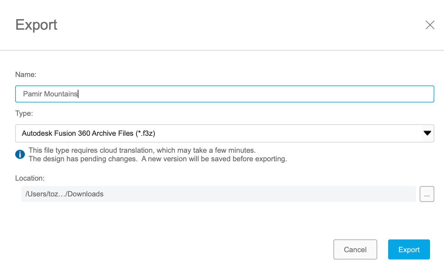
After creating the Pamir Mountains, now I can invert it to use it as a cutting tool from the Wax block I made earlier. To do this I have extruded a new object around 0.75 inch in height and the same size as the Pamir Mountains landscape and use combine tool and selected cut as option.
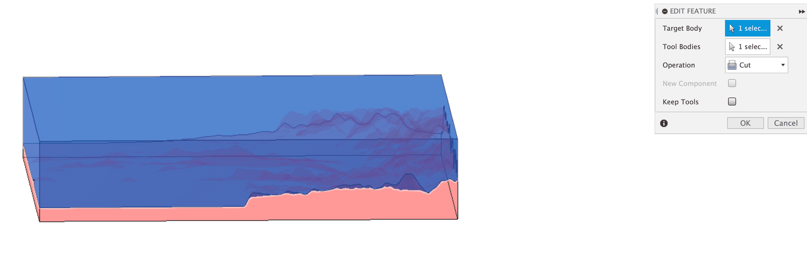
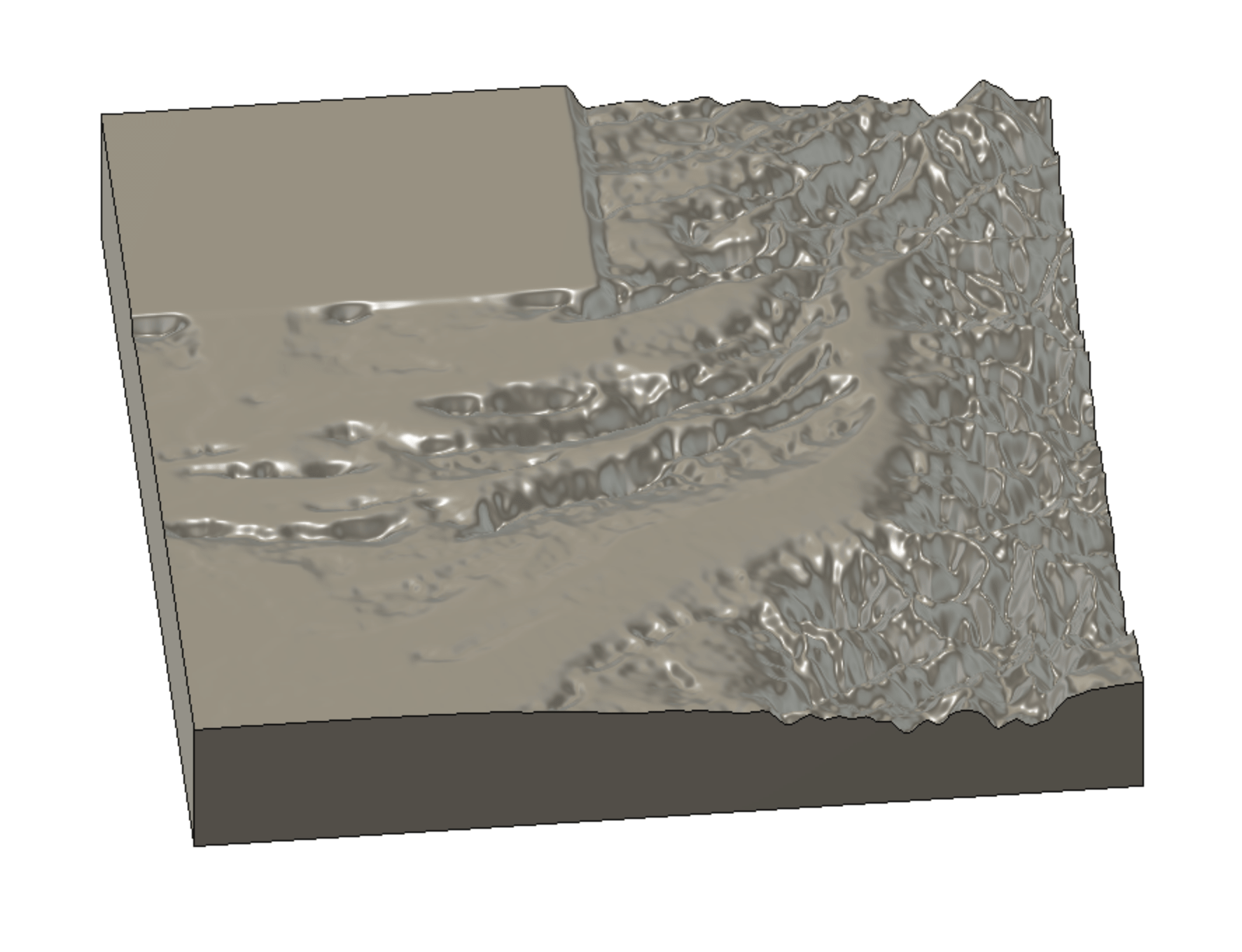
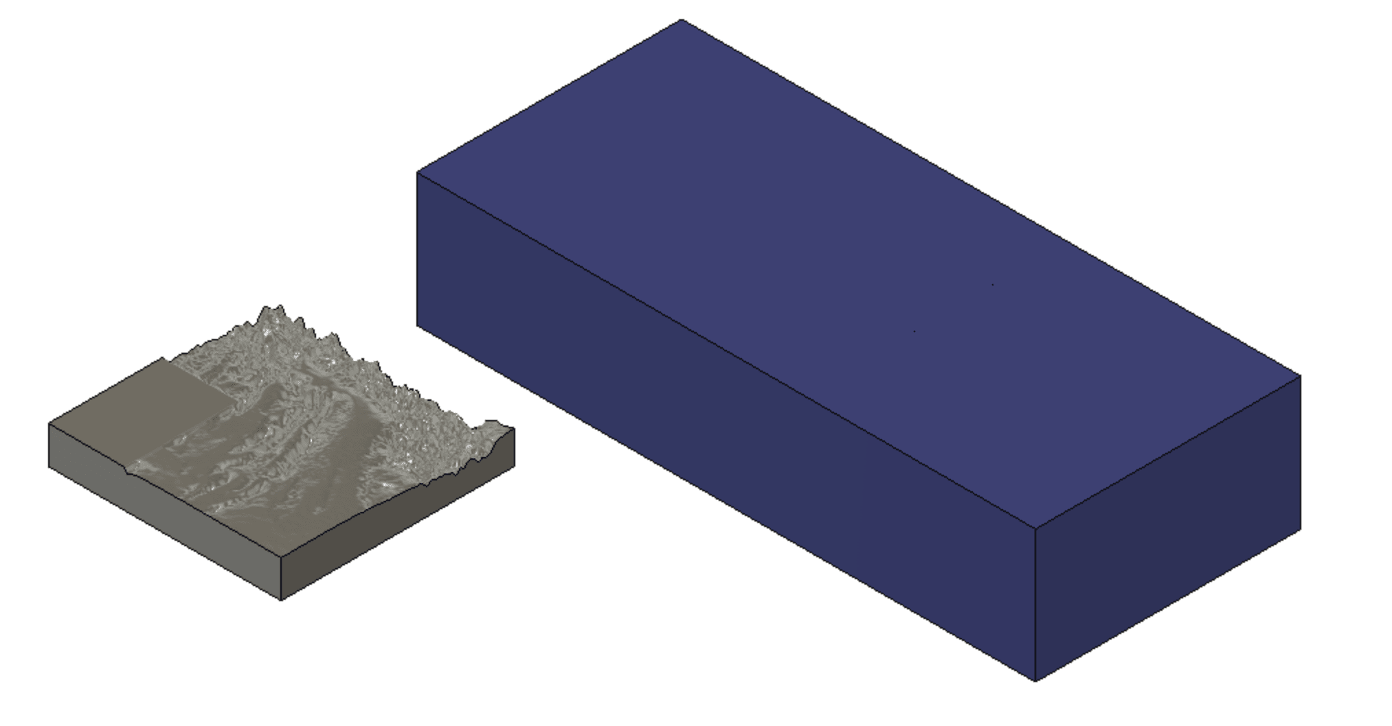
After using the combine tool as cutting operation I ended up with this.
Now that I have created the inverted version of the Pamir Mountains landscape object, I can use it as a cutting tool. However, for this I need to bring it to the file in which I created the Wax block in. Normally for this you can use the insert derive tool in Fusion.
However, because I created the Machinable Wax object file on a different project on Fusion, I had to do some extra steps. First I have exported the inverted Pamir Mountains as a Fusion 360 file.
After exporting it, I went to the Fusion 360 Project where my Machinable Wax file is located and used the uploadbutton to upload my Fusion 360 Inverted Pamir Mountains file. After doing this. now I was able to select which object to insert from the same Fusion 360 Project.
Now that I have imported my Inverted Pamir Mountains Object, I can turn it upside down and scale it to the correct size and put it inside the Wax where the back side of the Pamir Mountains is flush with the top side of theMachinable Wax.
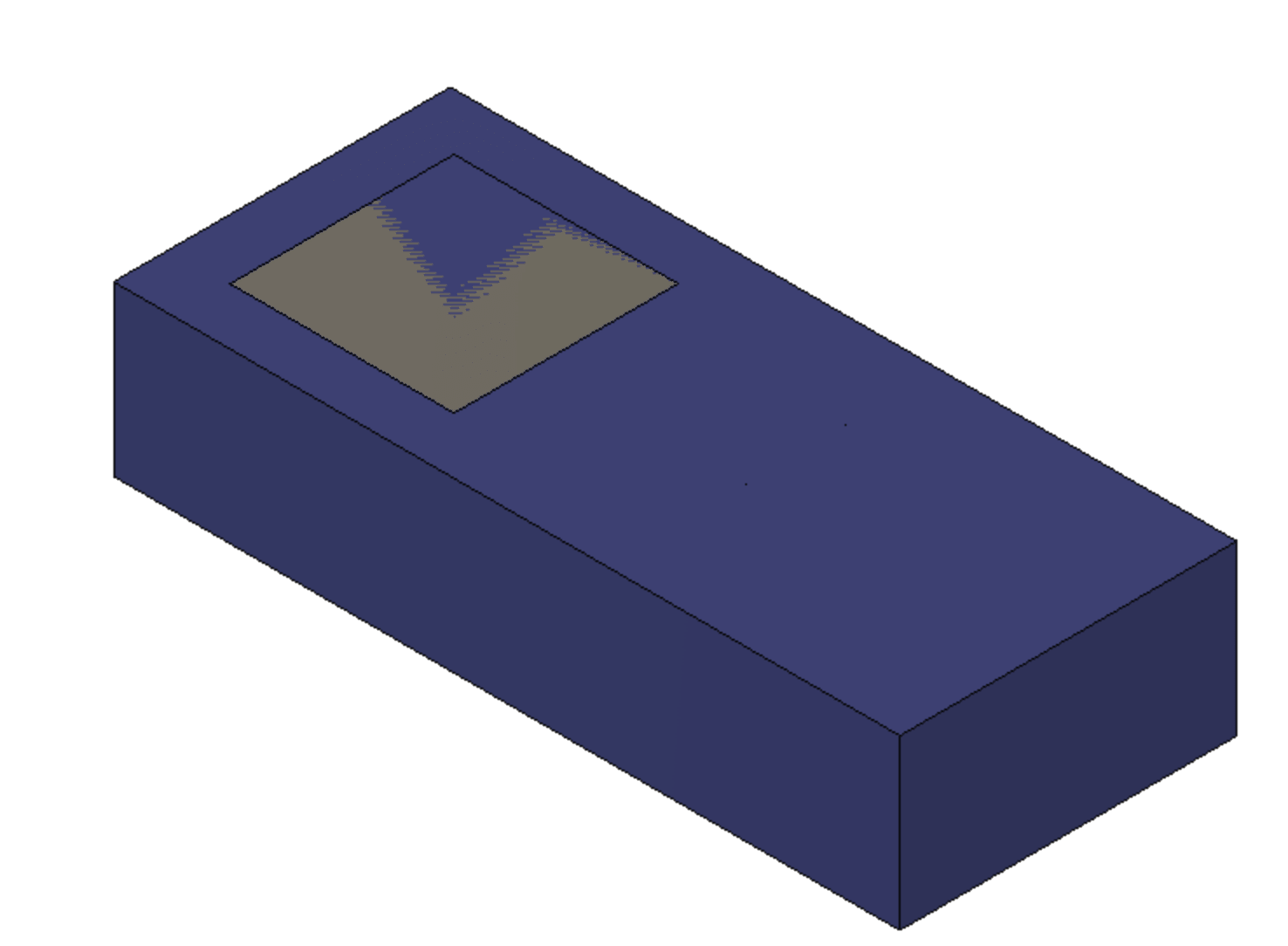
The reason I have done this is because I wanted my Pmair Mountains Object to start at 0.75 inch deep in to the object and because while I was doing the inverting step I have made the height of the object 0.75 inch I was able to make them flush and just cut like that. After making them flush I have used the the combine tool again and select cut as operator. After combining them them I have got this.
However, if I tried to use the Machinable wax as the moldfor the final project I wouldn't be able to get the piece out without damaging the wax or the piece or both. This is because the Wax is solid and not that elastic hence taking a solid piece out of it without damaging would be almost impossible. For this reason we will be using this Machinable wax to be a mold for another mold which will be used for making the final piece.
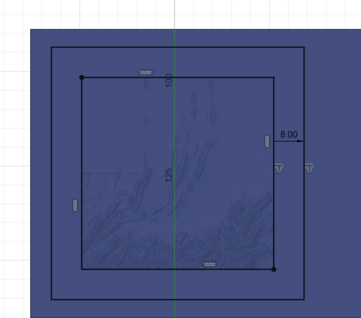
For this I need some spaces around the sides of the object and the sides should be a bit deeper than the Pamir Mountians. For doing this I have created a sketch and used the outline tool to create an outline of 8mm out of the perimeter of the cut square.
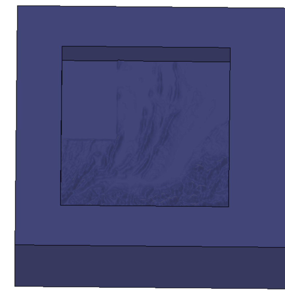
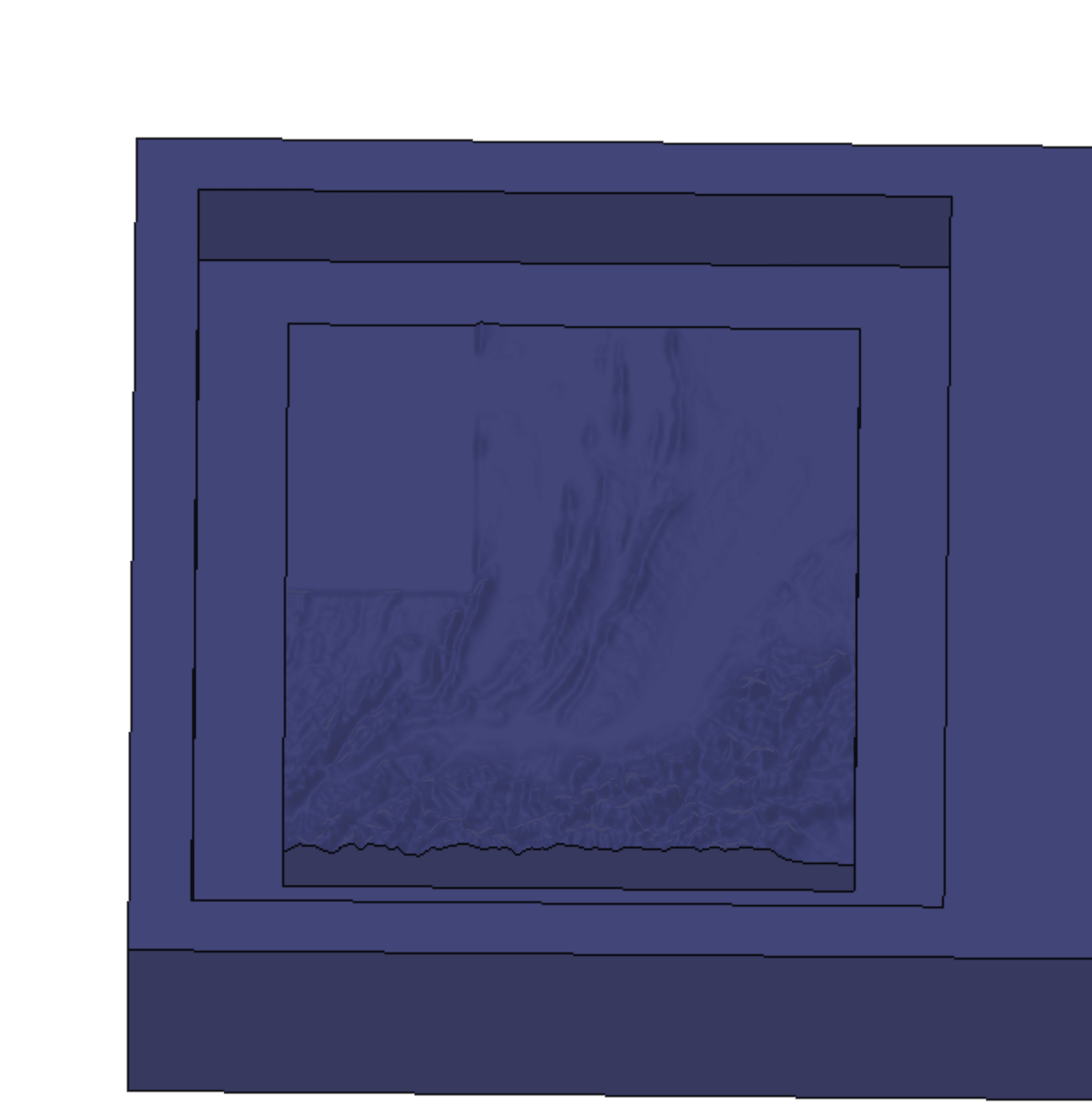
Now that I have my sketch using the extrude tool and cut operation, I have extruded it downwards by 1 inch and cut the part around the Pamir Mountains. It looked like this:
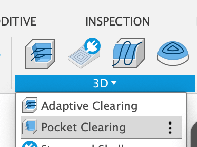
With that step the design part is done and I can start making toolpaths. Because the Pamir Mountains Object inside the Wax doesn't start until 0.25 inches deep inside the wax, we first need to clear the excesss material out using a big endmill. This is also the reason why the outline was 8mm previously, so that the big endmill can go in there and clean up everything. For doing this you can either use 2D pocket clearning or 3D pocket clearing. I used 3D pocket clearing because from my experiences with other people's files, using 3D pocket clearing gives more accuracte clearing.
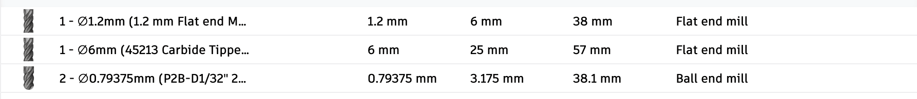
After selecting this tool, first we need to select which tools we are going to use. For this I have used the 6mm Carbide flat endmill from Amana Tools and changed the Spindle Speed to 5000 rpm from 18000 rpm. The reason to this Spindle Change is because Roland SRM-20's usual spindle speed is around 4000-5000 rpm.
After selecting which tool we need, we need to select which area to cut. For this we go to the second tab and for Machining Boundary I selected "selection" and clicked on the square aroun the Pamir Mountains
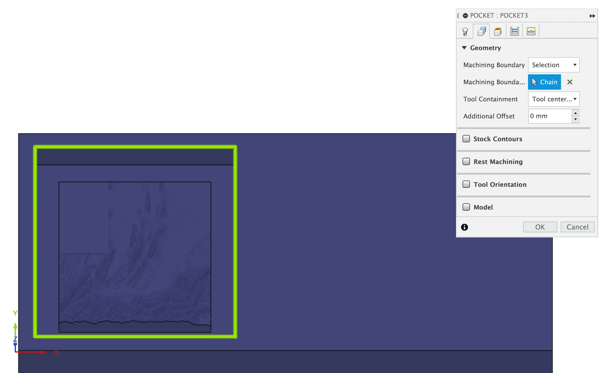
After Doing this, I have disabled the "stock to leave" so that the endmill will cut out everything it can. And I have changed the stepdown to 2mm from 6mm. The reason to this is because this endmill is suppose to turn at 18000 rpm and have astepdown of 3-6 mm. However, Rolan is not that powerful hence if you try to have 3mm stepdown at 5000 rpm Spindle speed it just crashes into the wax and does not turn, I am speaking from experience.
Now that we have completed out first toolpath, I have moved on for toolpaths for the smaller endmills. I only want to mill out the details on Pamir Mountains and nothing else, so for this reason I have selected 3D Parallel Cutting and for the MAchining Boundary I have selected the Bottom region of the Pamir Mountains.
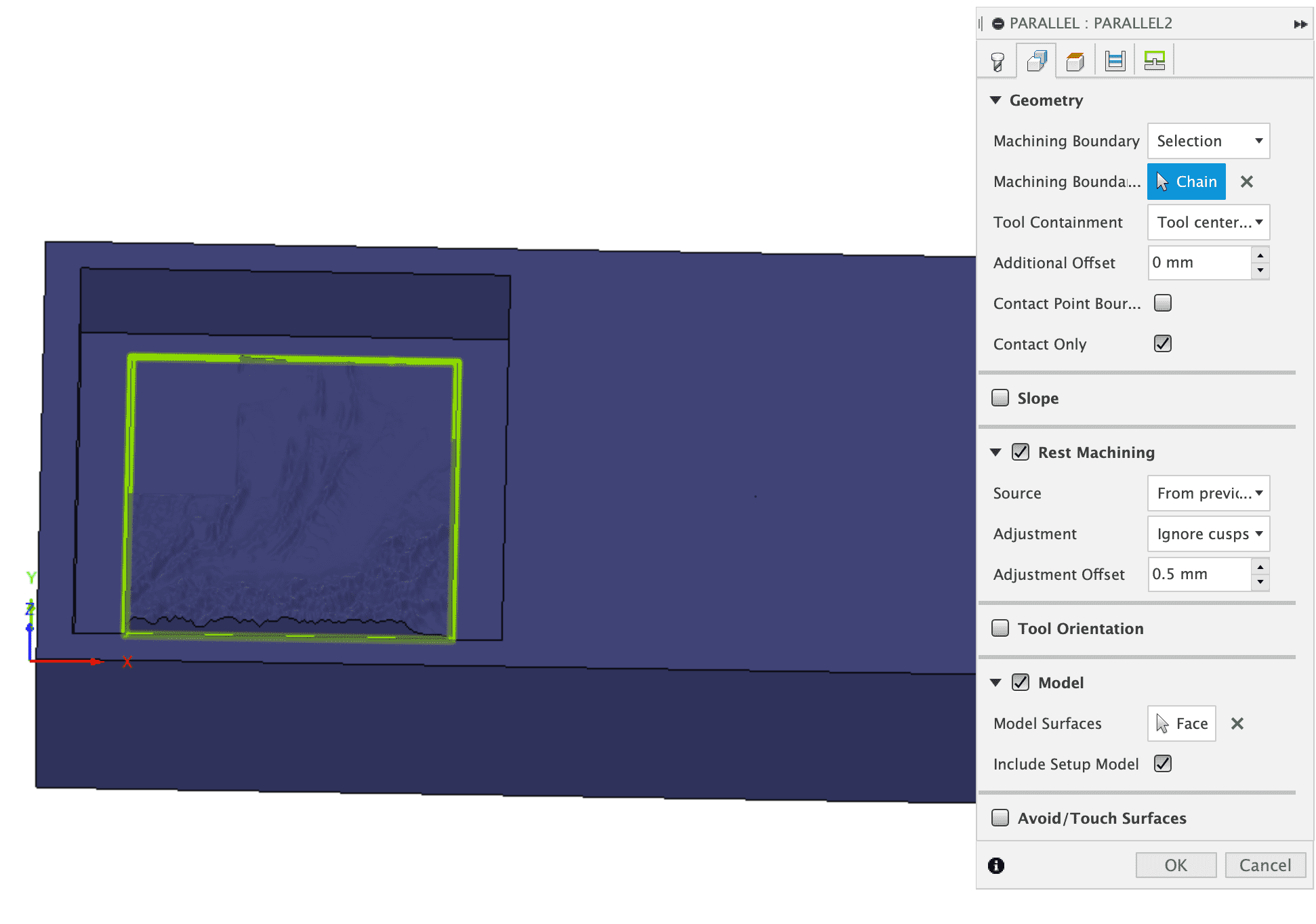
After selecting this, I have selected the endmill I will use. For this I have selected 1.2 mm endmill from the list above. Also I have enabled "Rest Machining" this looks through previous toolpaths and calculates which areas are cut and only calculates toolpath for the rest of the material.
I have made one more 3D parallel toolpath using a 1/32 inch ball nose endmill. This is for a lot more precision and smoothing.
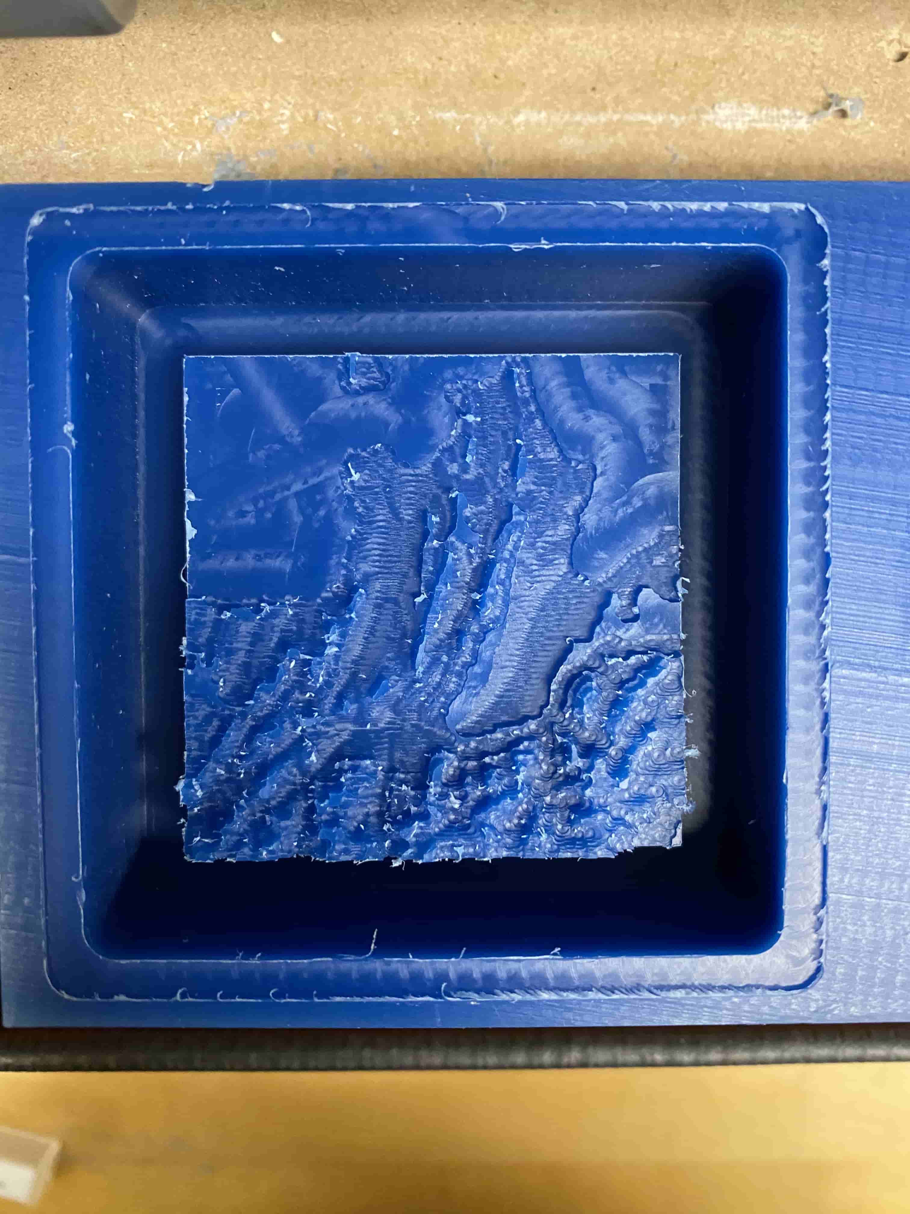
This is how it looked like after the first roughing cut with 6mm flat endmill:
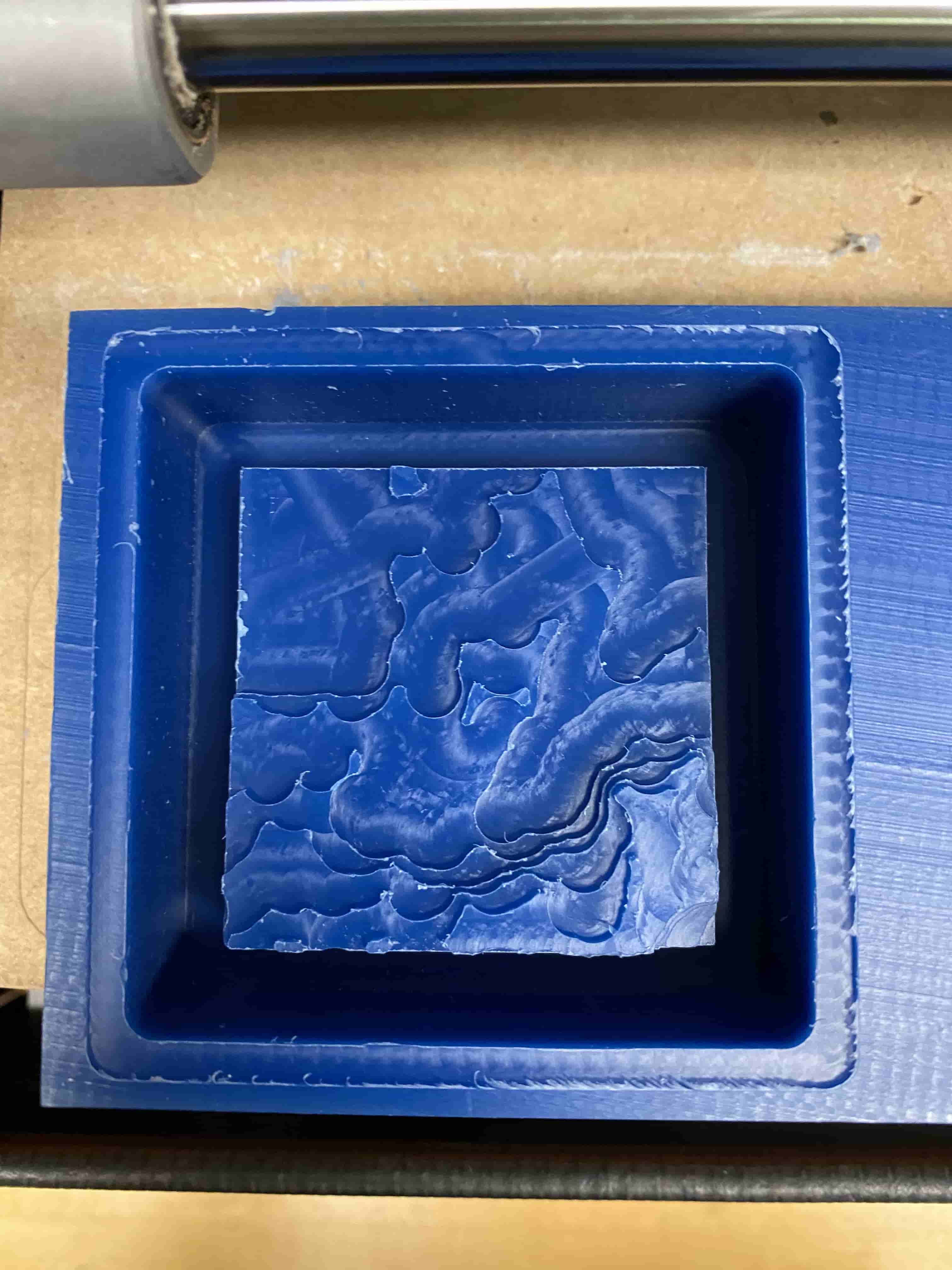
This is the results of 1.2 mm flat endmill cut:
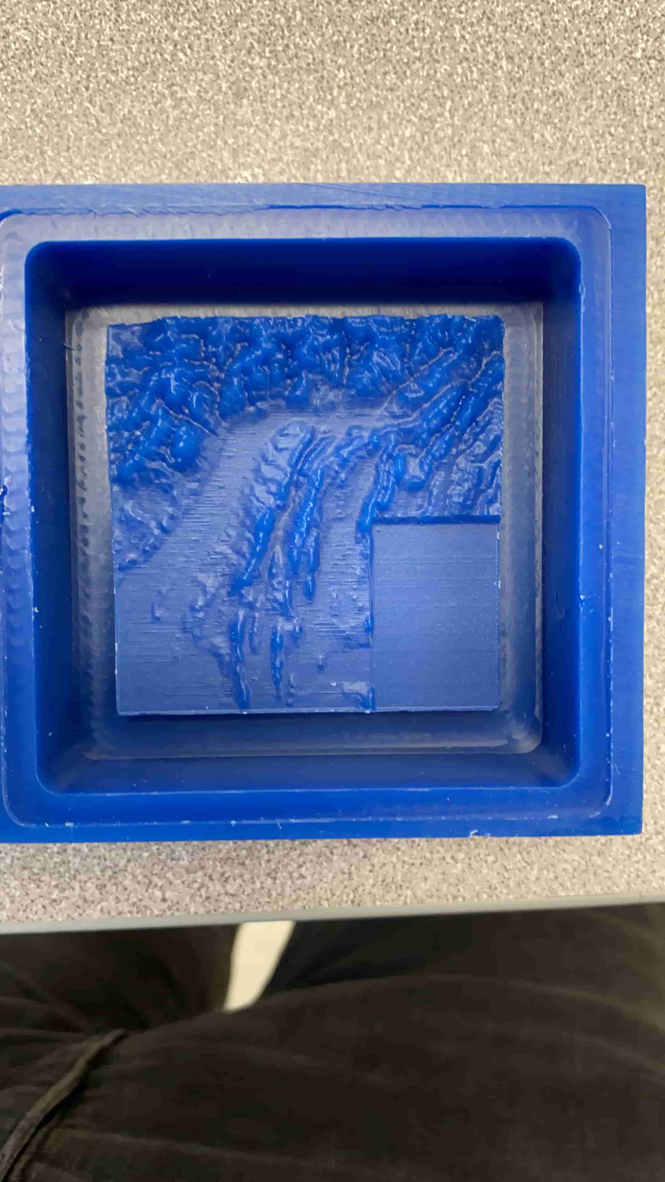
This is the result of 1/32" ball nose endmill cut:
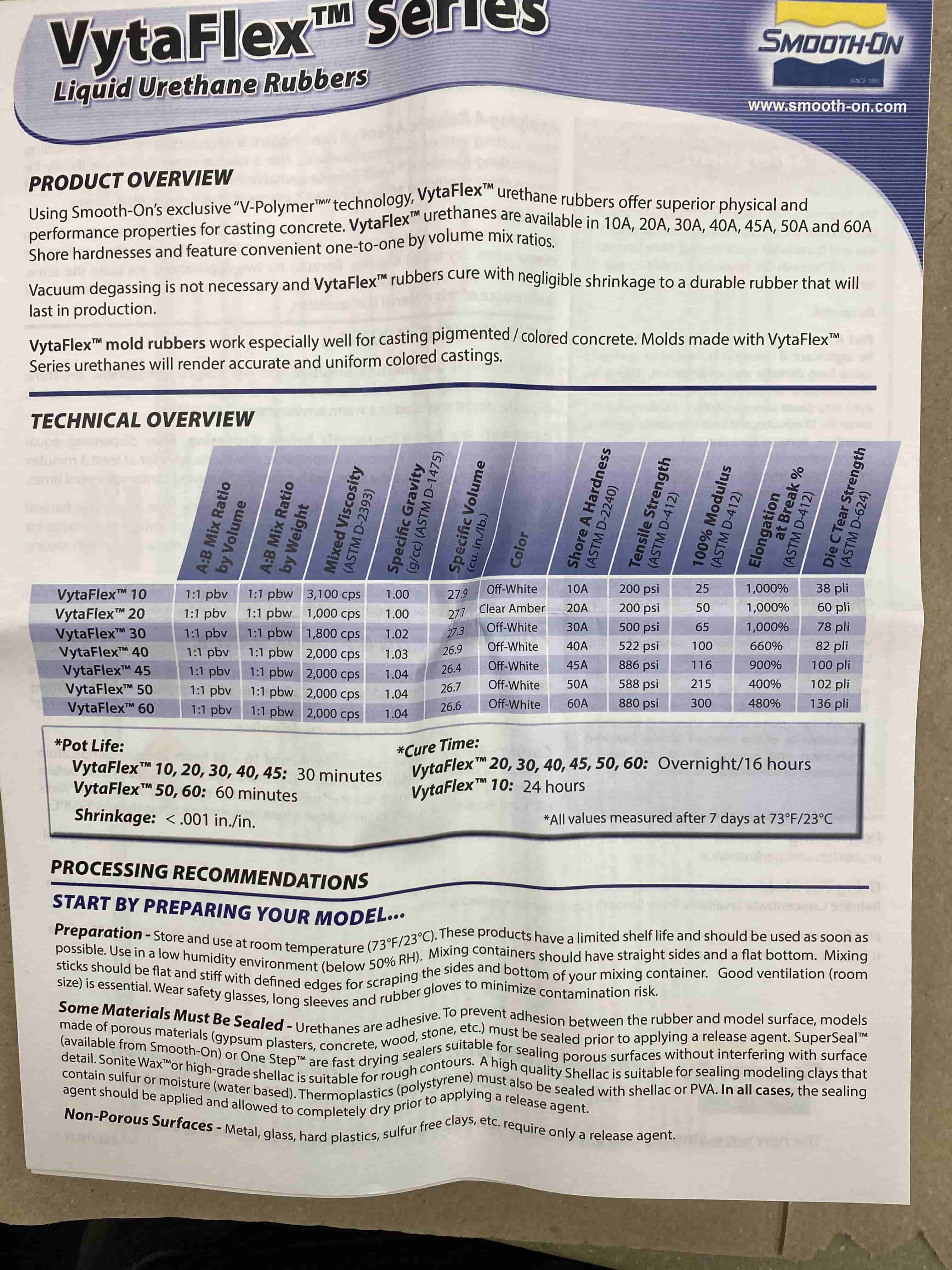
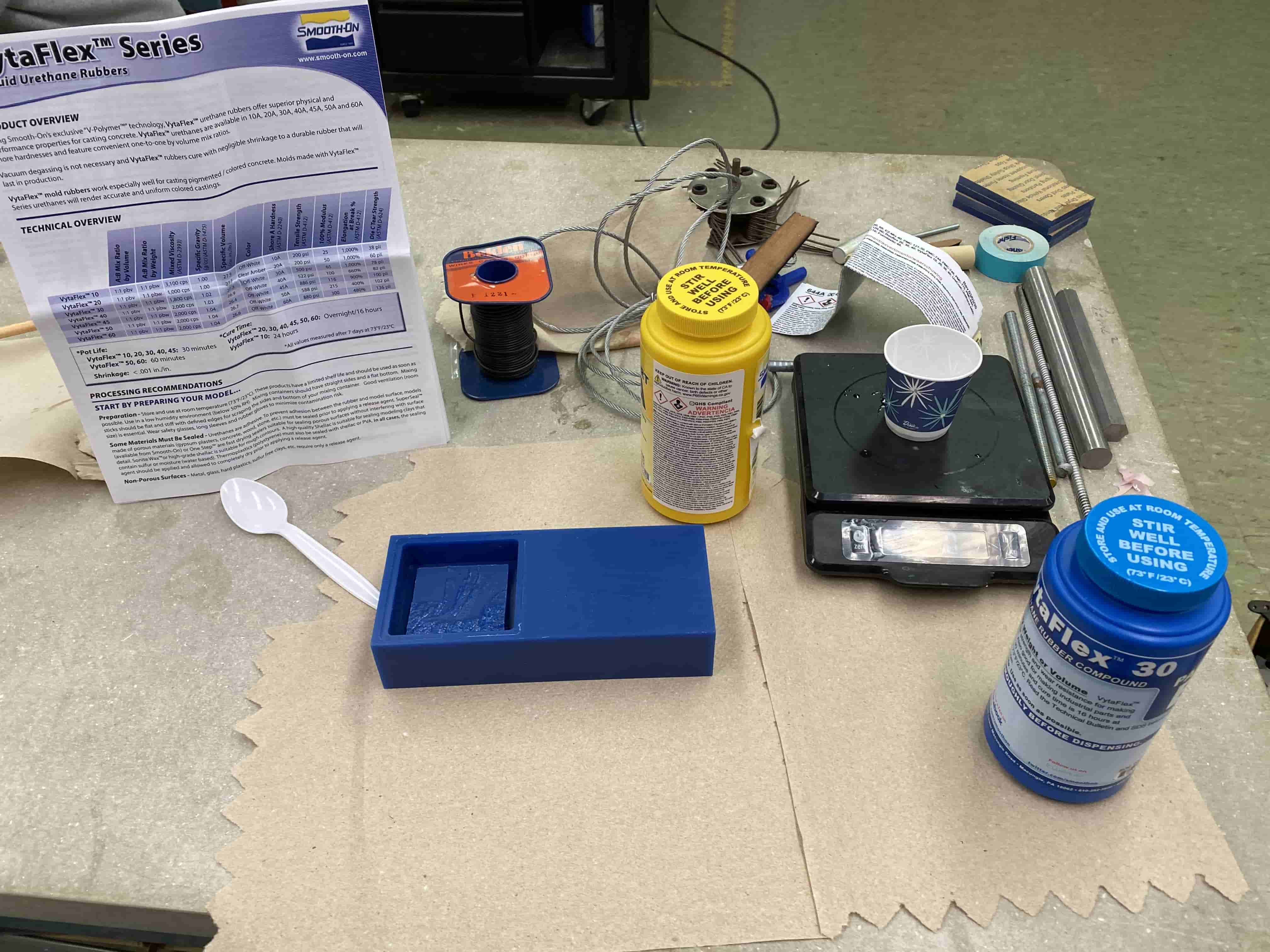
After maving my wax ready I can use it for making my mold. First I have selected the one that will fit my purpose. I was planning on using a fast hardening plastic mix for my final piece, hence, I need to use a mold material that is elastic. For this I have chose VytaFlex.
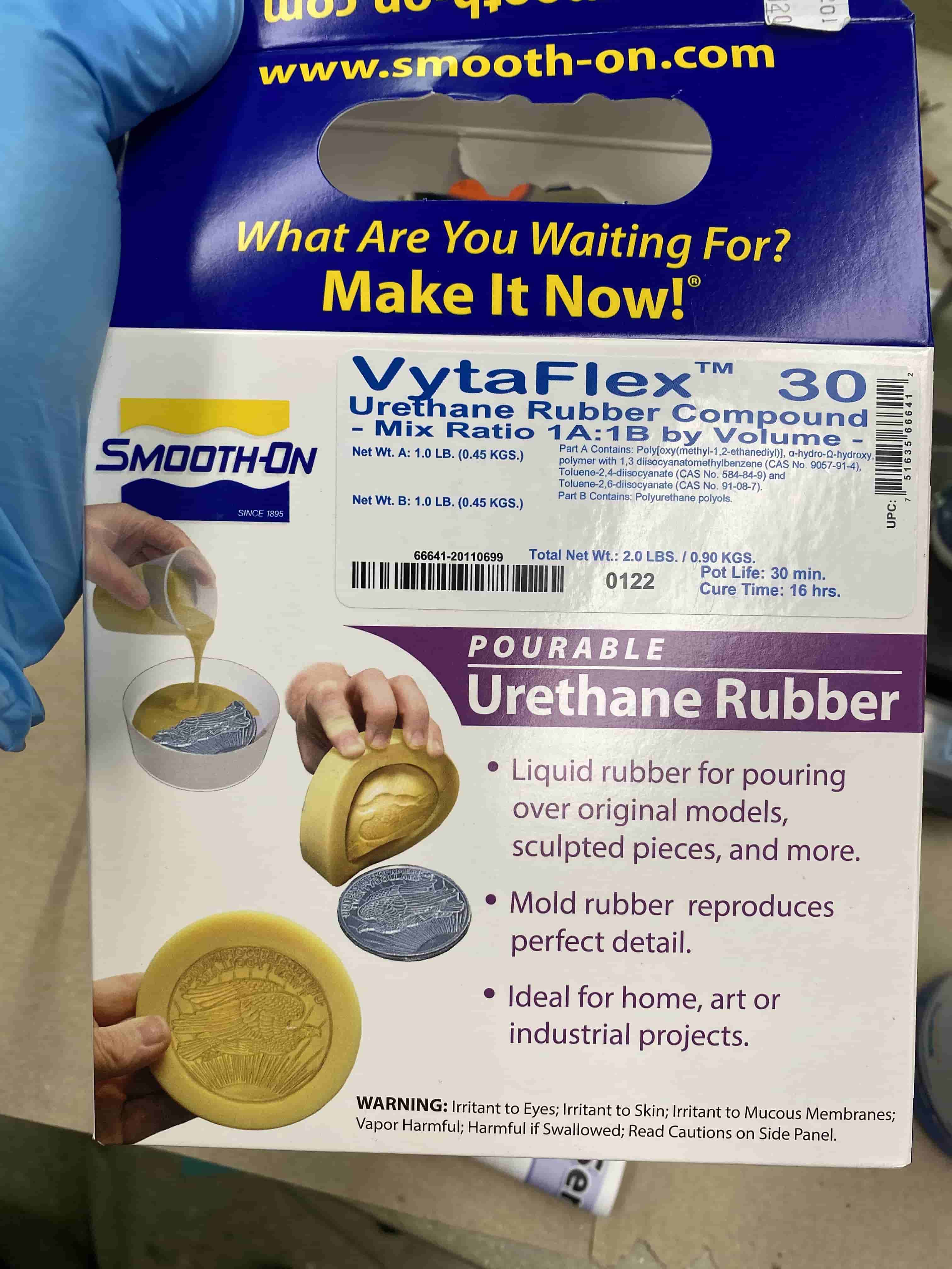
Unfortunately, afterwards I will realize that I selected the wrong material. Beforestart using this mold I need to readthe instructions on how to use it.
I wanted to use the by weight ratio to make my mold so I used a scale rather than volumetric cups or pipettes.
Before starting mixing and pouring stuff, I first weighted my wax object and zero the scale, which then I have filled the wax object with water and weighted it again. This allowed me to see how much I can fill it. Even though the viscozity/densitiy of the liquids I will be using for molding is very different than water, I can use this to have an estimate on how much to fill. I have calculated that I need 70 grams of mix, and the by weight ratio was 1 by 1 hence I have prepared 35 grams from mix A and Band started mixing them vigurously. After 30 seconds, I have poured it inside the Wax and put the Wax inside a Vacuum Chamber for few seconds. After this I let the Mold sit and cure for 24 hours.
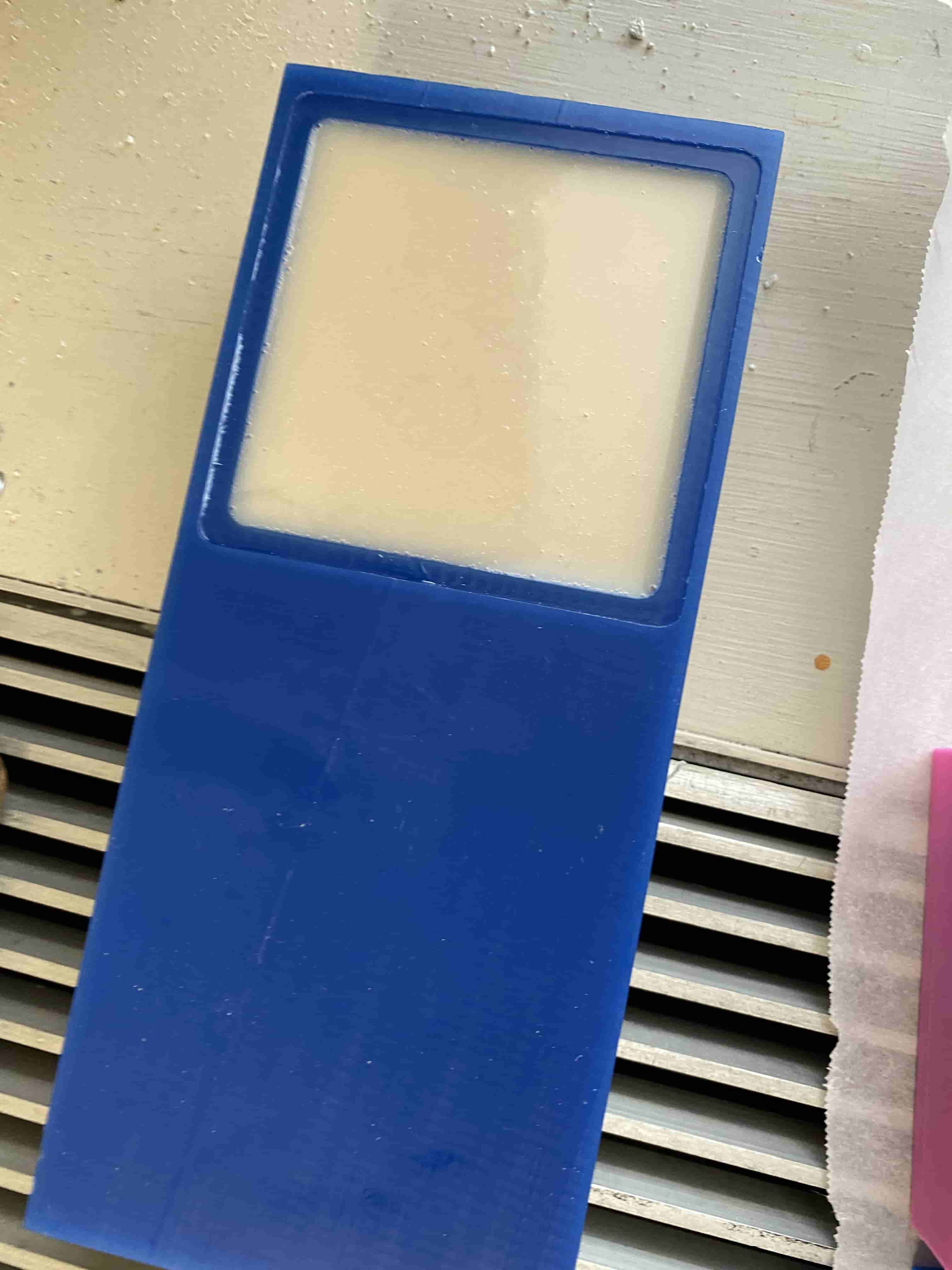
After letting it cure for 24 hours, I had a really detailed mold. I thought because my object is really detailed maybe my mold wuldn't be able to completely replicate it but I was wrong and it came out great.
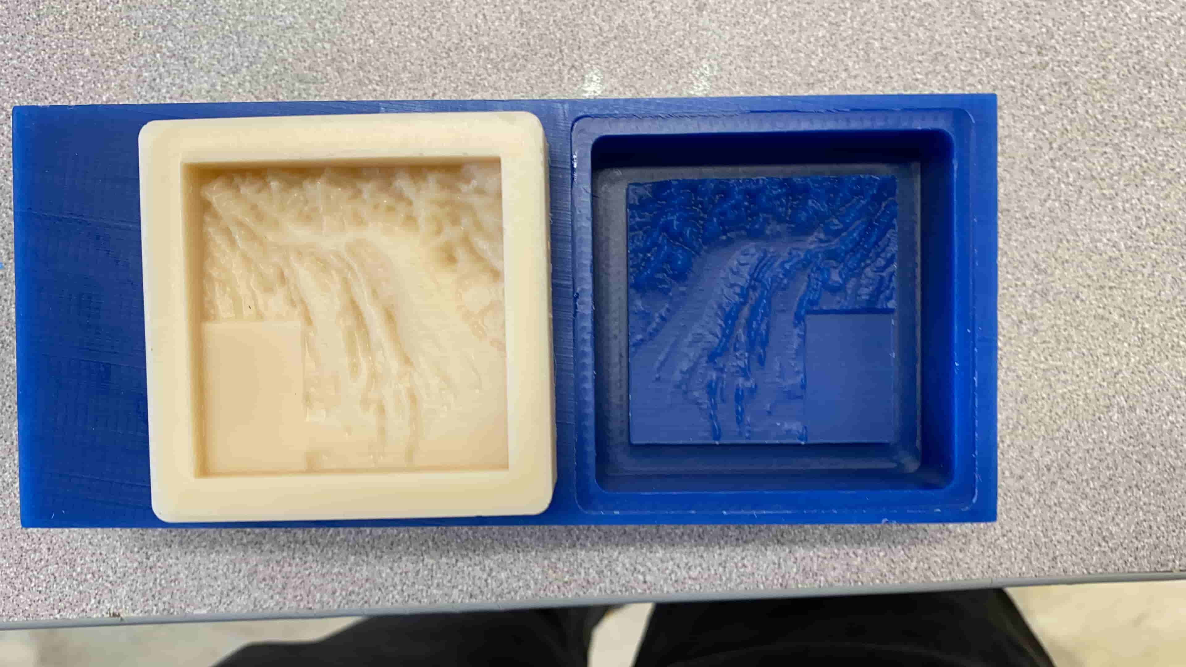
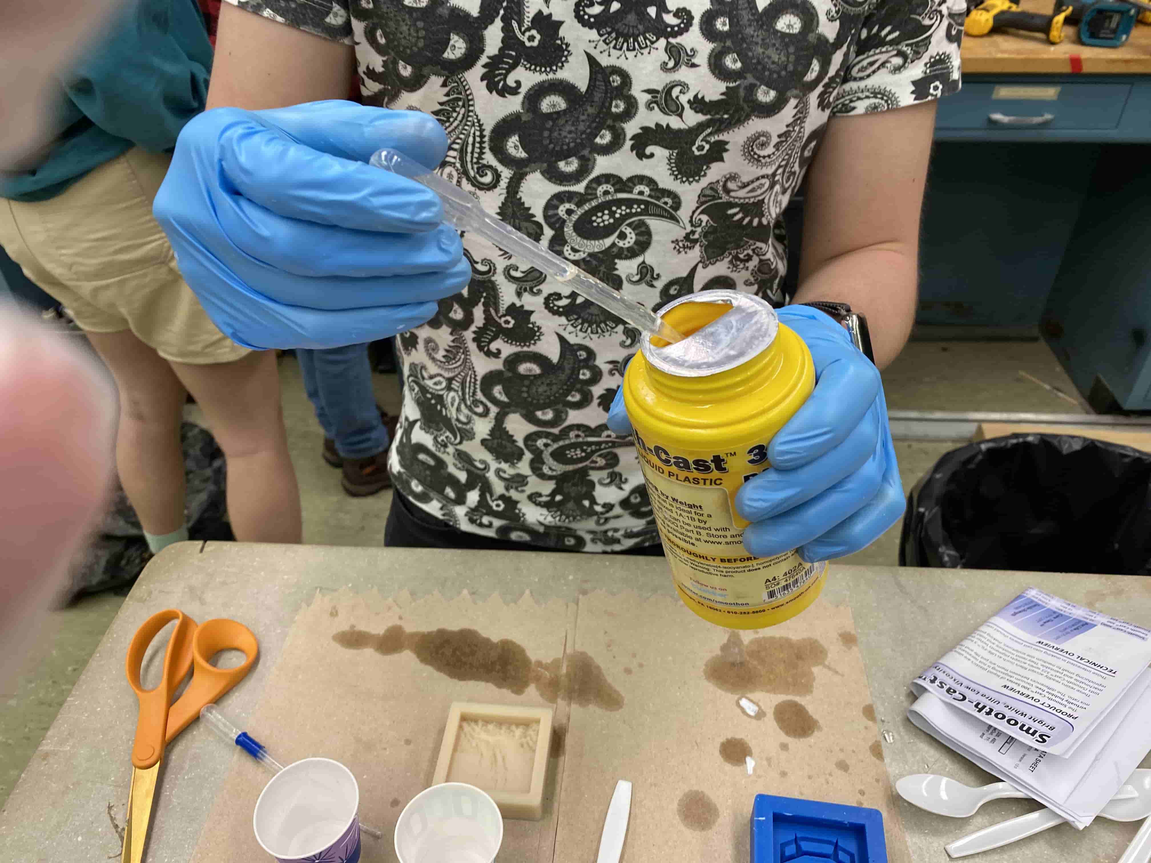
After finishing my mold, I went forward and got a different mixture to make my object. This time I have used the by Volume ratio. After reading the instructions, I saw that I need to have 1by 1 Volume ratio. I did the water filling method again and I got around 20 ml. However, once I saw that the mix A was so dense I have decided that I will do 40 ml. I have used pippettes to measure how much I need and I filled two seperated cups for A and B liquids. So that Once I have the enough amount I can mix them.
Fortunatelly, unlike the mold,for this piece to cure enough for handling it only requires few minutes. Hence, after waiting few minutes, my object was ready. Unfortunatelly, I selected the wrong material for the mold because, when I tried to take out my object from the Mold, it was stick to it. and I had to rip my mold a bit so that I can take it out.
Fnally it looked like this: