Assignment:
Group Assignment:
1# Measure the analog levels and digital signals in an input device
Individual Assignment:
1# Measure something: add a sensor to a microcontroller board that you have designed and read it
Brainstorm
Softwares:
 - Fusion 360 - A CAD software that allows both 3D and 2D designing
- Vpanel - A CAM software that talks with Roland SRM-20 Desktop mill to send the job
- Fusion 360 - A CAD software that allows both 3D and 2D designing
- Vpanel - A CAM software that talks with Roland SRM-20 Desktop mill to send the job
 - MIT Mods - a great software that allows CAM software for multiple devices at the same time
 - Adobe Illustrator - a great software that allows editing and manipulating vector images
Machines:
 The Arduino UNO is the best board to get started with electronics and coding.
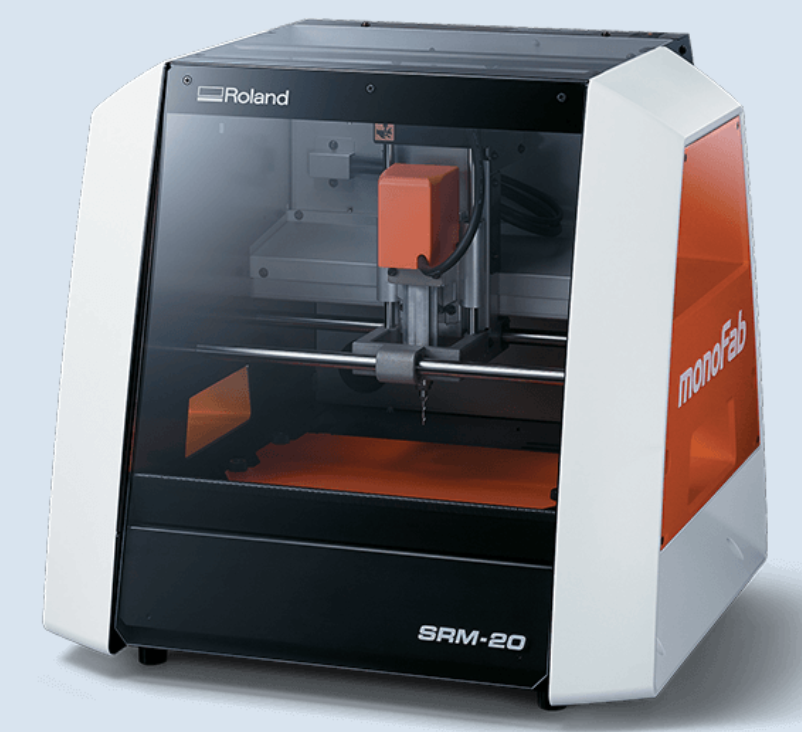 Roland SRM-20 - it is a precision mill that can hold variaty of small endmills ranging from 0.3mm to 6mmm diameter endmills
Tutorials:
Group Assignemnt
For this weeks group assignment we have used variaty of different devices from joysticks to photoresistors. We have used a breadboard, a 5V power supply, a resistor and various input devices. We have used the breadboard to layout our circuit and we have used the resistor to record the voltage changes using a multimeter across the resistor once we connect the input devices and play with them.
In the GIF above you can see that I am using a Joystick to change the Voltage through the resistor. We have connected the VCC and Ground of the Joystick to the VCC and Ground respectively. This powers up the Joystick the same way a potentiometer works. The reason to this is because a Joystick is a combination of 2 potentiometer and a button.
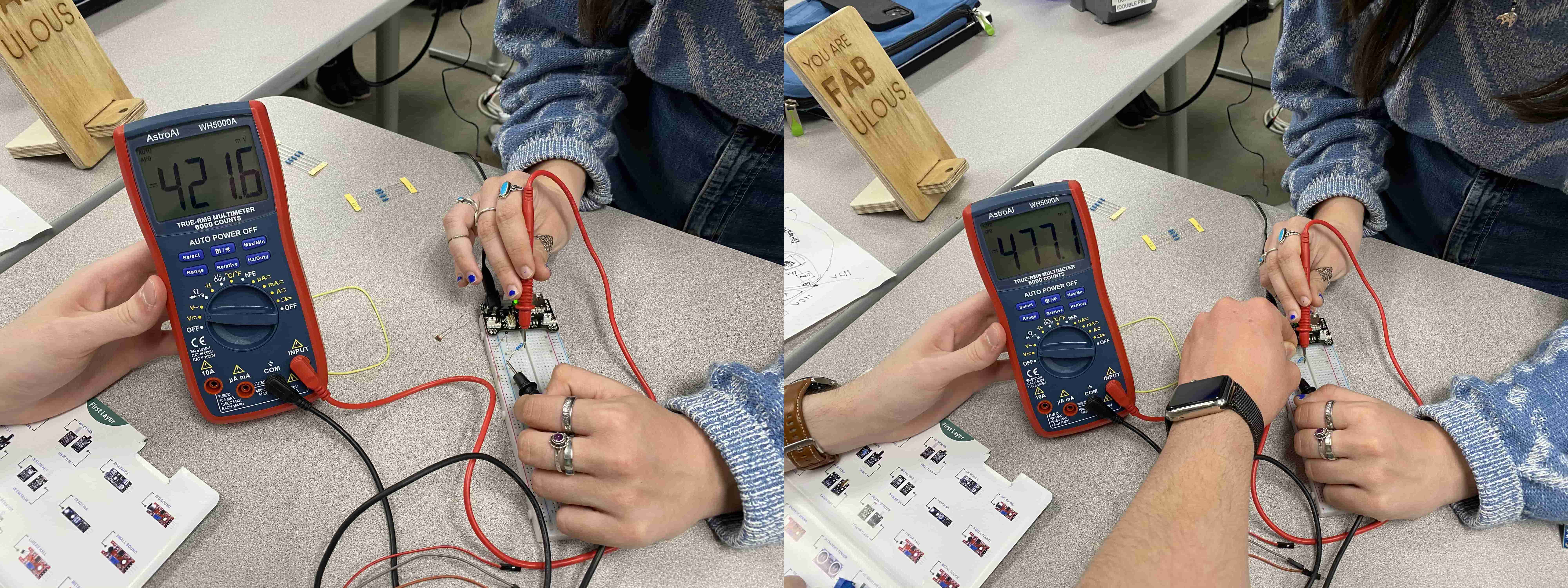
Afterwards, we have tried a thermistor. We have plugged it in series with the resistor. Unlike the joystick (potentiometer), the thermistor acts as a regular resistor which changes its resistance according to the temperature of itself. In the picture you can see in the first picture the Voltage through the resistor is lower and once I hold the thermistor and warm it with my fingers the voltage through the resistor increases.
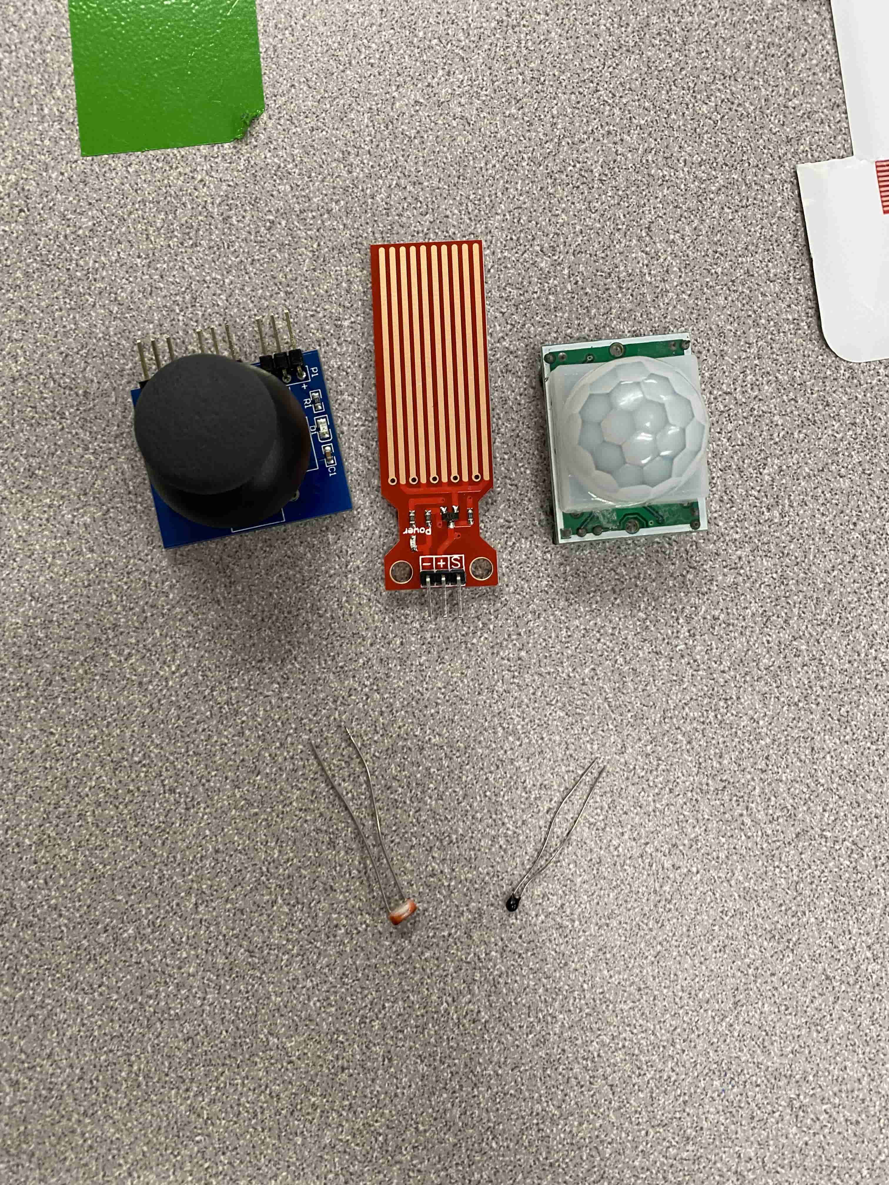
We have tested all 5 devices above and we got different results from all of them. The Joystick's button function requires a pull up resistor to register on the microcontroller because the button is connected to the ground rather than the VCC.
Moreover, we learned about pull-up resistors and pull-down resistors, nano accelerometers, gyroscope. I have linked the power point with all the imformation here.

Afterwards, we went forward with designing our own circuits in ThinkerCAD. I always wanted to use an LCD display and I also thought this would be a good practice for my final project. On ThinkerCAD I opened the example project for LCD 16x2 Display and then edited abit to have a button. Then I have changed the code a bit so that everythime I press at the button it increases the Count on the LCD Display.
At the end it looked like this:
Individual Assignment
For this weeks Individual Assignment, I wanted to use a Joystick to complete the assignment. I was thinking of making a board where I can read the data from the Joystick. However, I then realized that it would be too simple. Hence, I started my personal project: Building a GameBoy. However, before starting designing my board and moving on to milling, I have decided that I will first use an Arduino Uno and breadboard to make the samething.
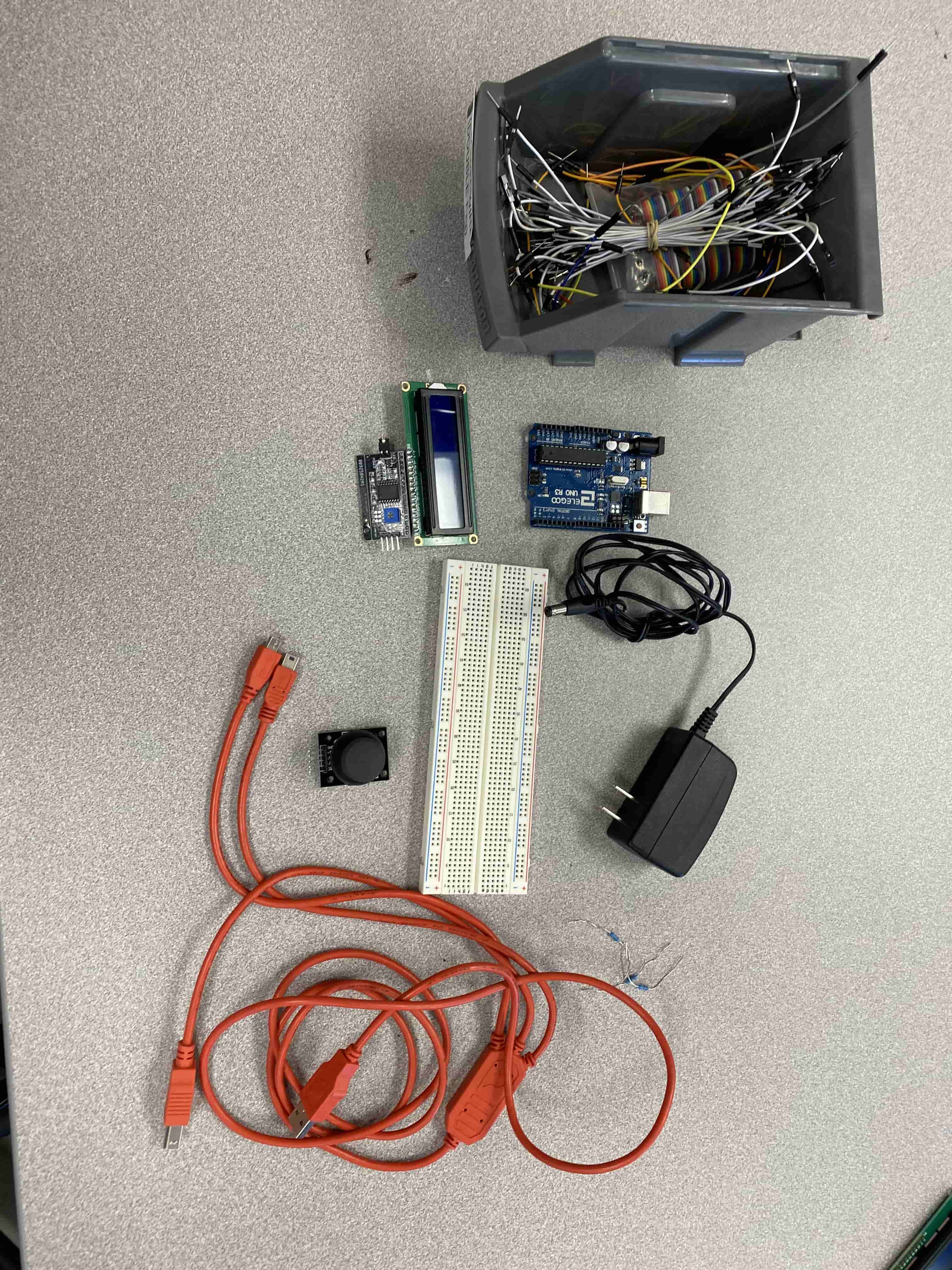
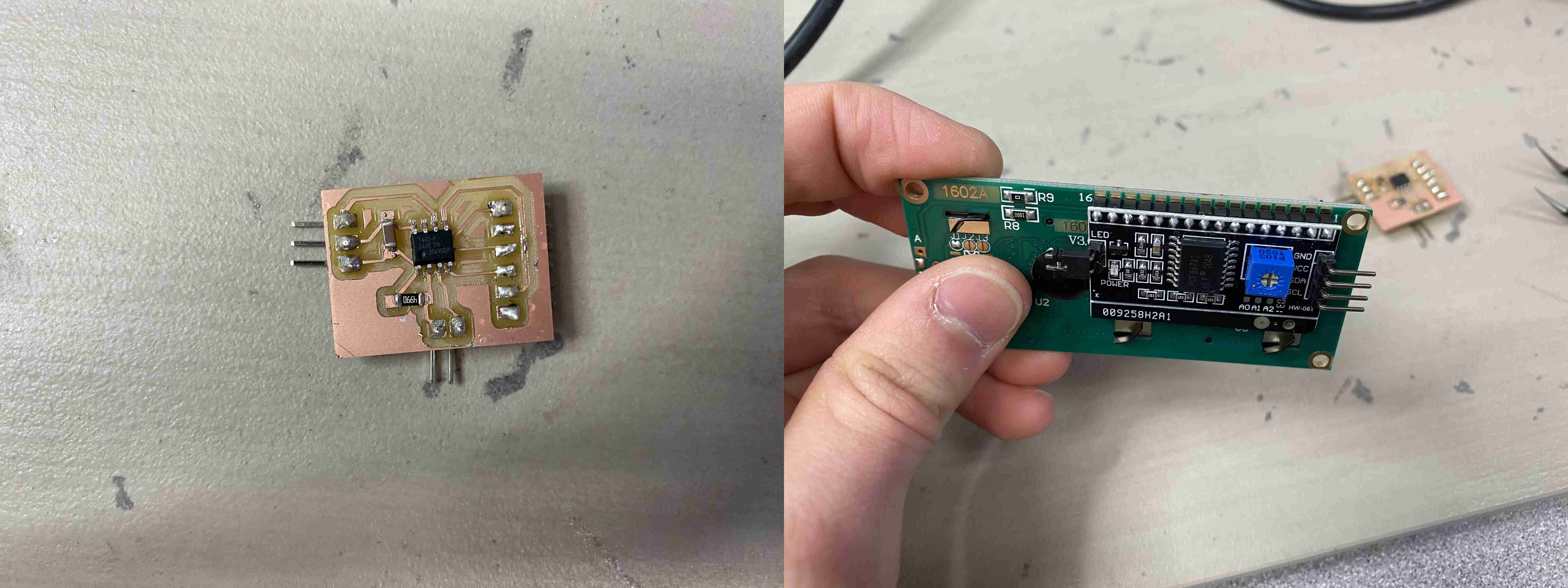
These are the devices I have used for this week's assignment. Some Dupont Wires, 12V DC power Supply, Arduino Uno, a Joystick, LCD 16x2 Display, 12 pin to I2C converter, a breadboard and a USB-B to USB-A cable. My initial step was to be able to turn on the LCD display and display a message there. However, even after trying an example code from LiquidCrystal LCD Dsiplay Library, I was not able to display a message.

In the tutorial it shows how to connect the I2C adapter to the Arduino uno. I have followed the steps and I was able to light up the display.
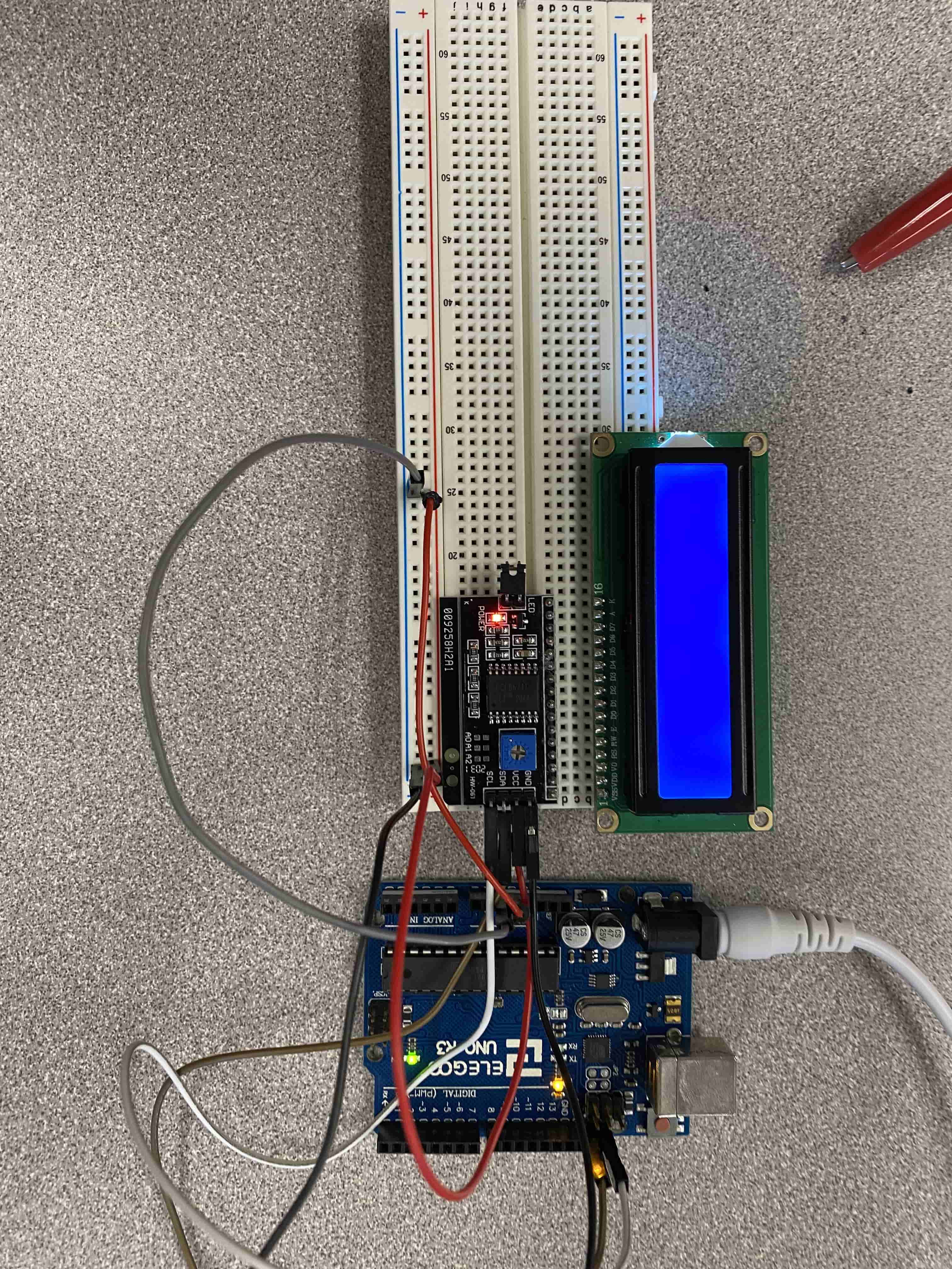
After Following the tutorial I have linked above. I learned that I need to increase the constrast of the Display so that the LCD Display can start displaying. Unfortunatelly, for me this took a while because the LCD display I was using was not working, so I have tried with another one and guess what, that one wasn't working neither. However, the third time is the charm, I was able to display "Hello World!" message using the example code.
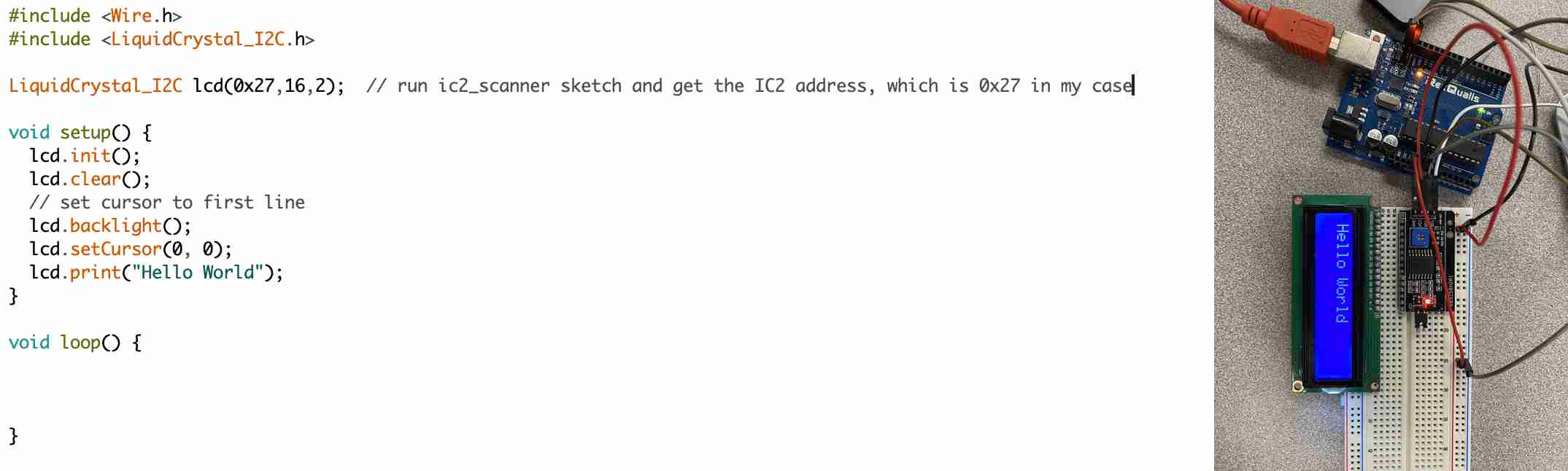
In the code as you can see, I have a line that says "LiquidCrystal LCD(0x27, 16, 2)." LCD is the LiquidCrystal object that is created by giving the parameters: 0x27, 16 and 2. 0x27 stands for the I2C connection adress of the Display, 16 stands for how many columns there are and 2 stands for how many rows there are on the LCD.
If the LCD has a PCF8574 chip from Texas Instruments, its default I2C address is 0x27Hex. If the LCD has a PCF8574 chip from NXP semiconductors, its default I2C address is 0x3FHex. To find the I2C address of the LCD Display, I have used the Nick Gammon's code.
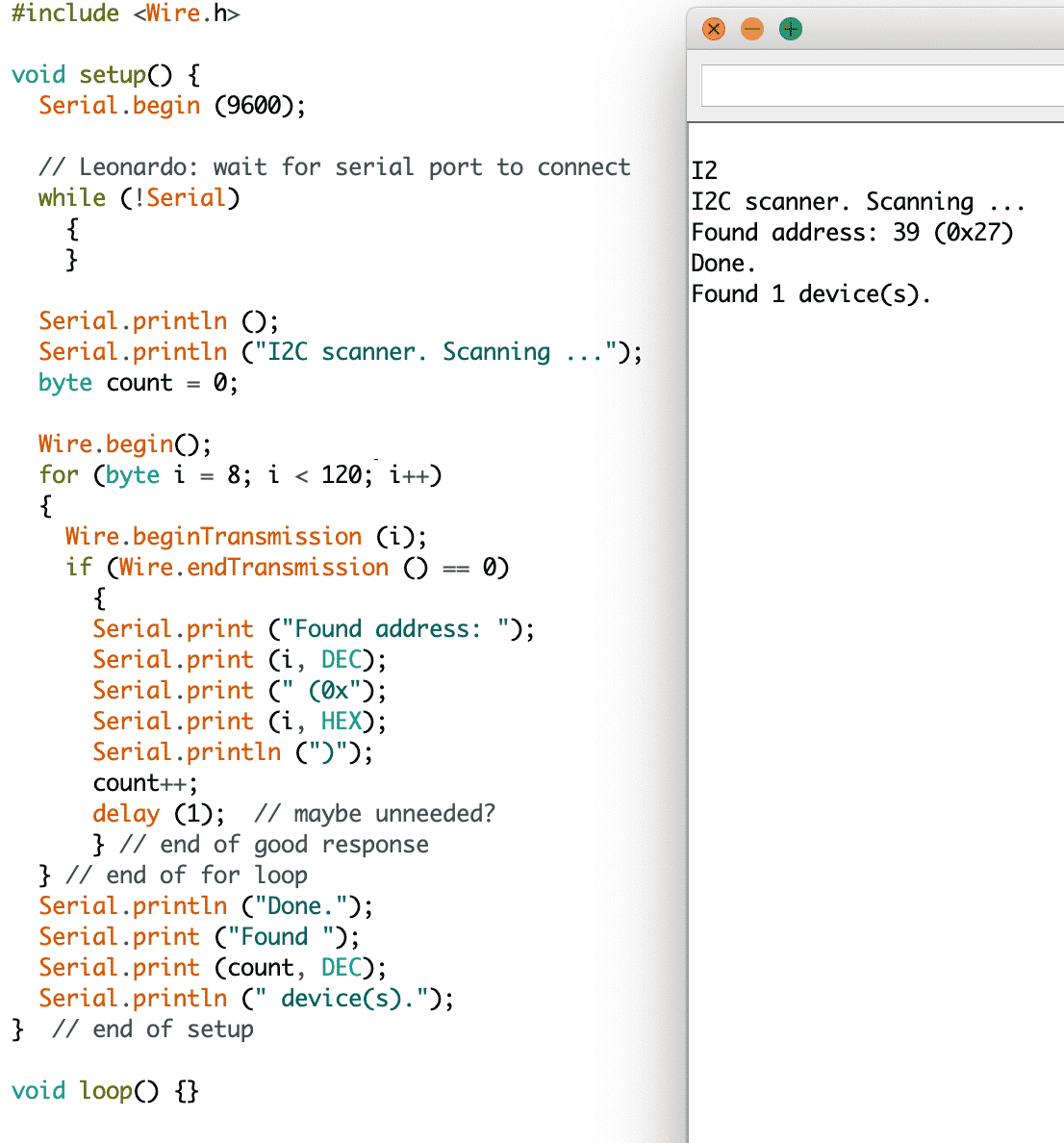
As you can see, his code allows me to find what's the I2C code of my Board is. After finding which I2C address I need to use, I have added it to my code. Later on to initialize or to start or to begin the LCD we use LCD.init() method and the rest is obvious from the names of the function.
After following the tutorial, I have learned that I can create my own emojis or designs etc. This was the place where I got the idea of creating my own GameBoy. I created my own character using the bit designer on the tutorial page. Then I have started coding my game.
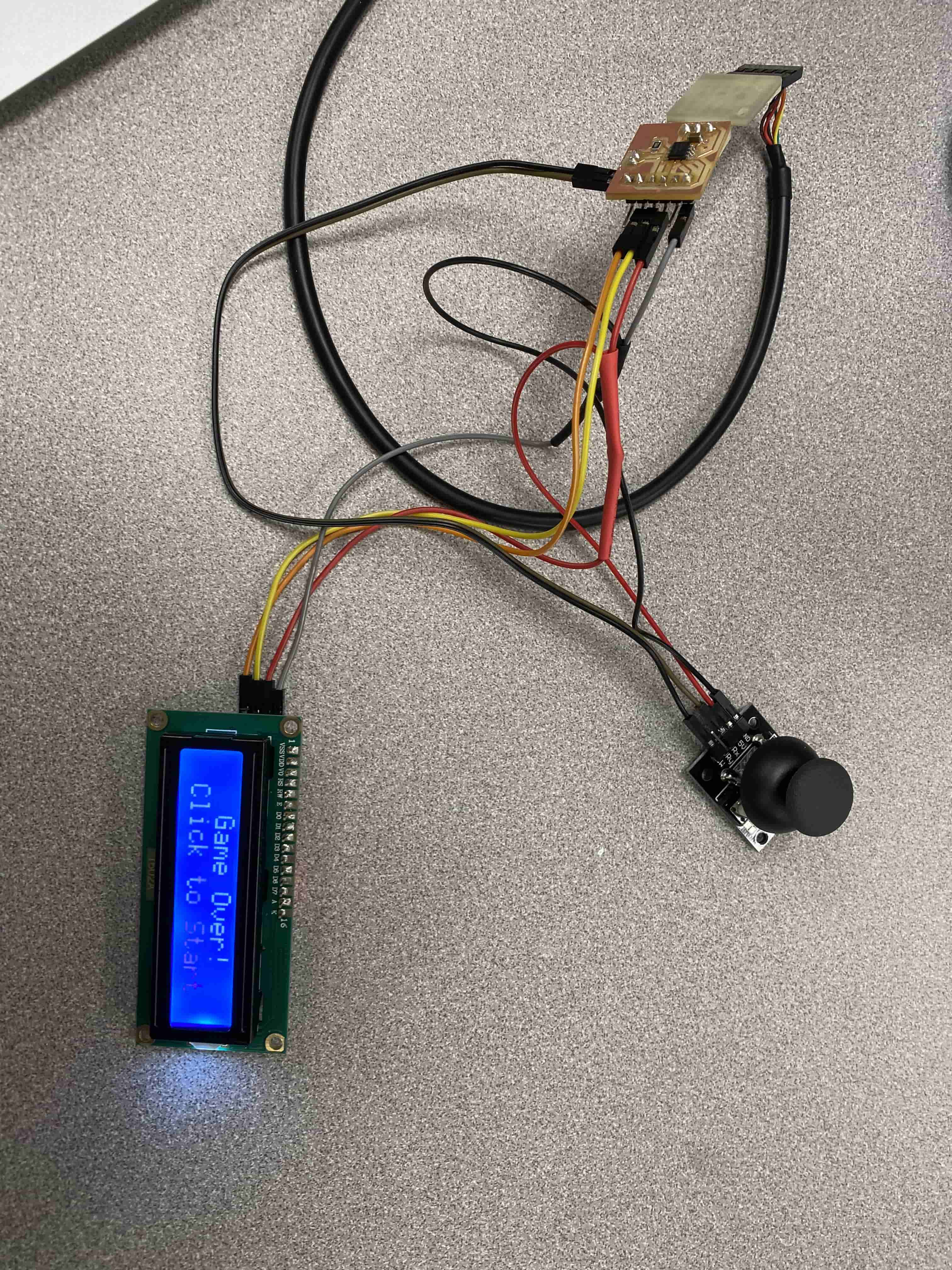
I have made a game where, you try to doge aliens by jumping. I got the inspiration from Google's Dinasour Game. However, There was no Gameover, so I started coding it. As you can see by using the Joystick I was able to control my Character. At first I was not able to jump. Even though my code was correct, I was not getting any input from the Button click on the Serial Monitor.
Testing the Joystick (Input Device):
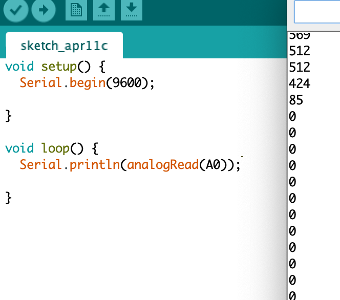
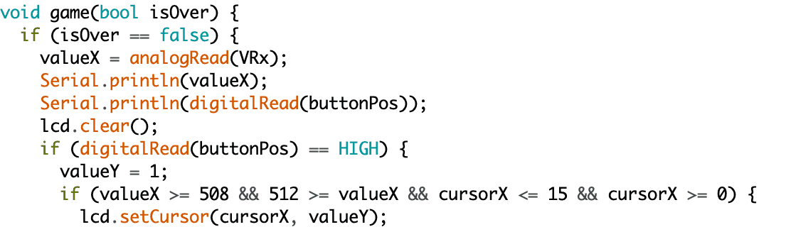
The above photo shows both the button press and the joystick analog input. Because analogRead can read an input from the normal button like digital instead of writing a new code I just changed the cables for testing the potentiometers or the button. As you can see in the beginning we have big numbers that comes from the potentiometer but when I connected the button, it only gives zero. That is because the button is connected to the ground. The way that a joystick works is that, it has 2 potentiometers one horizontally (X-Axis) and one vertically (Y-Axis) and a button. With AnalogRead you can read the resistance off the potentiometer and you can also read the ON/OFF signals from the button. However, because the button is connected to the ground in the joystick you need to connect the pin in your microcontroller to High/VCC/Positive and use the button as a pseudo pulldown resistor to turn off and on the current to that pin.
After some thinking I remembered froum our Group Assignment that some buttons require a pull-up resistor to work. Hence I have added a pull up resistor and I was now able to jump and then I have implemented the gameOver code.
Now that my game is ready and working and that I know how to connect everything I have started Designing my own board on kiCAD. Because I will be using lot's of not SMD parts I have decided that I will have lots of connectors that will connect to the microcontroller.
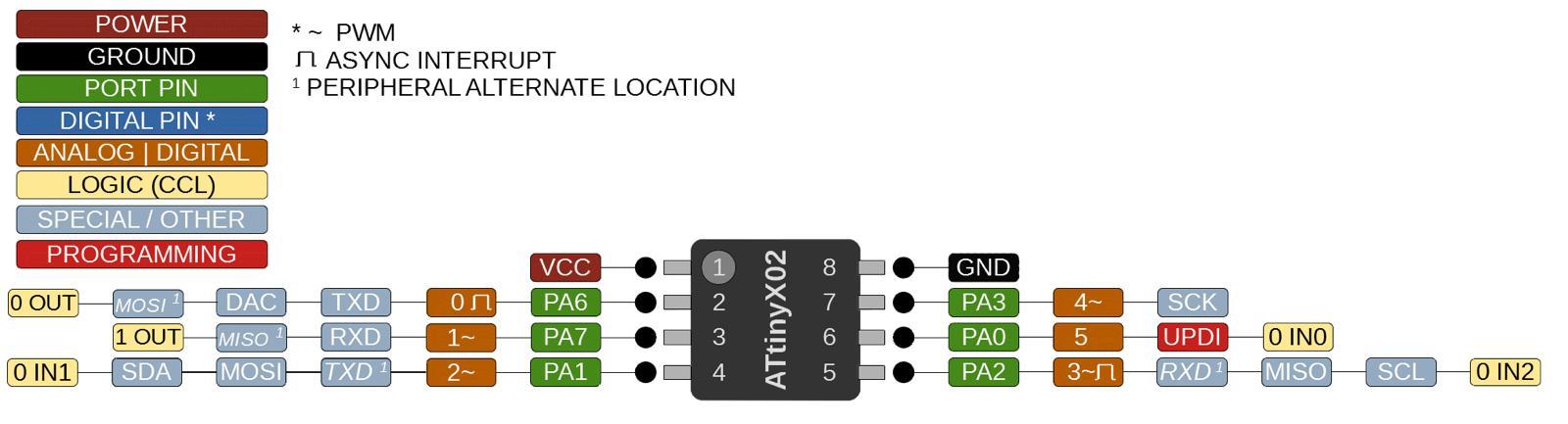
I have decided that I will be using an ATtiny402 because I only need to use the VCC pin, Grounf Pin, an Analog Pin, a Digital pin and the Pins for SCL and SDA for I2C connection.
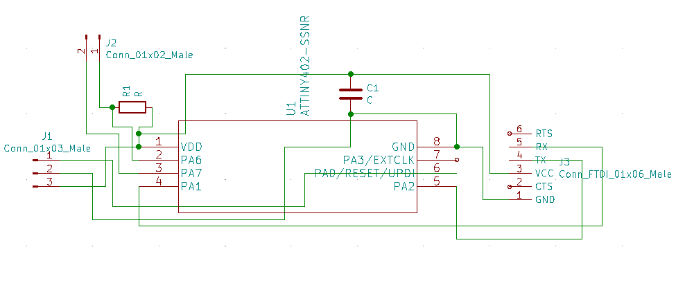
I have included a pull-up resistor and a capacitor to makesure that nothing goes wrongs while I am trying this out. For this design I have imported the symbol and footpring libraries of ATtiny402 to kiCAD.
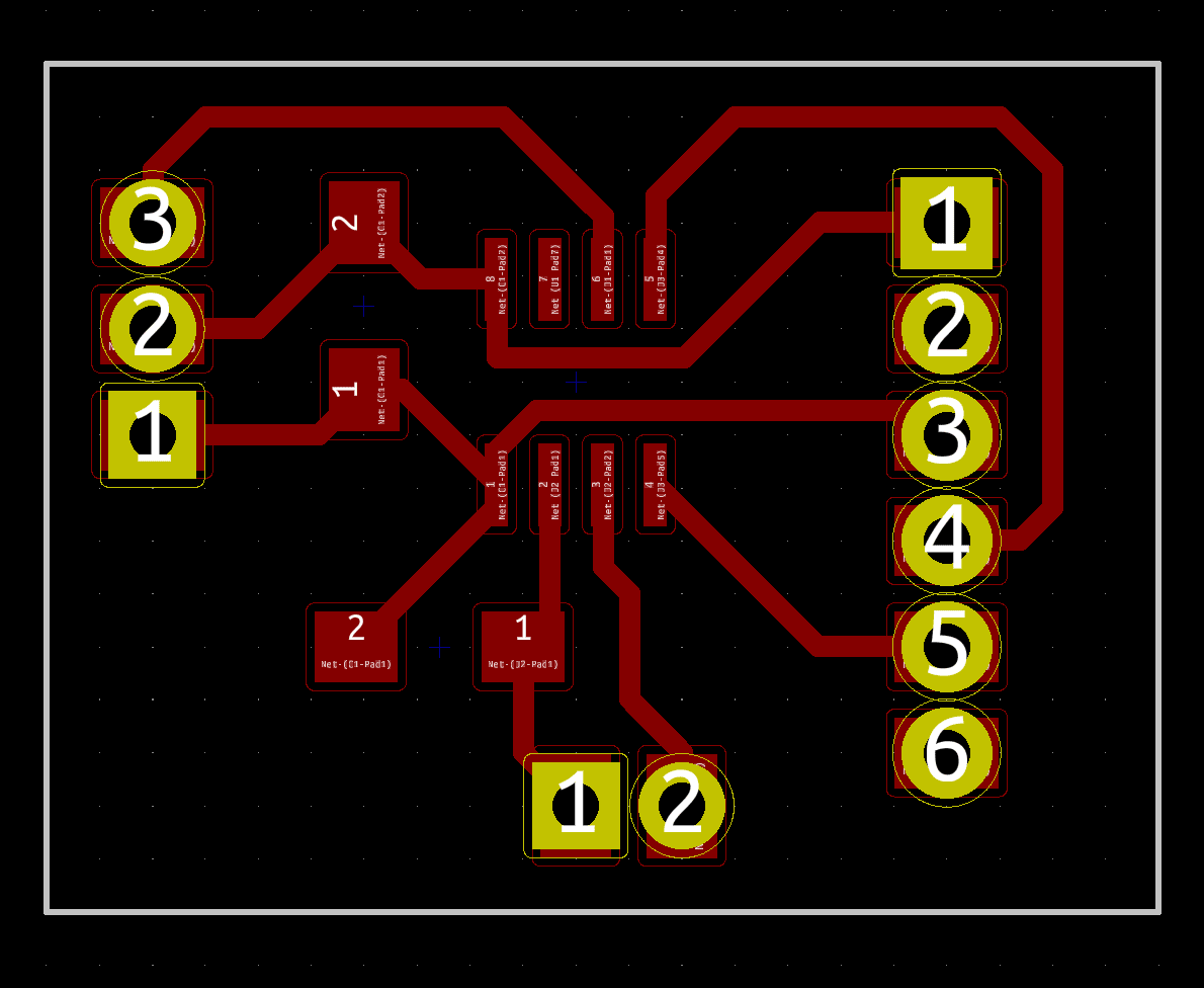
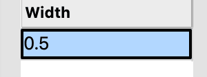
Because I have so few SMD components, it was really easy to trace out the whole board. I have layout the pieces accordingly and every connection was really linear and easy. I have increased the line thickness from 0.25 mm to 0.5 mm. The reason I did this is because I wanted to ensure that the traces are thick enough. Once I was finished with tracing I have exported it out as an SVG file.
I then used Adobe Illustrator to take that SVG file and turn it into 3 seperate files. Which then I have used Mods to convert them into tool Paths. After this stage I have uploaded it into Roland Precision Mill.
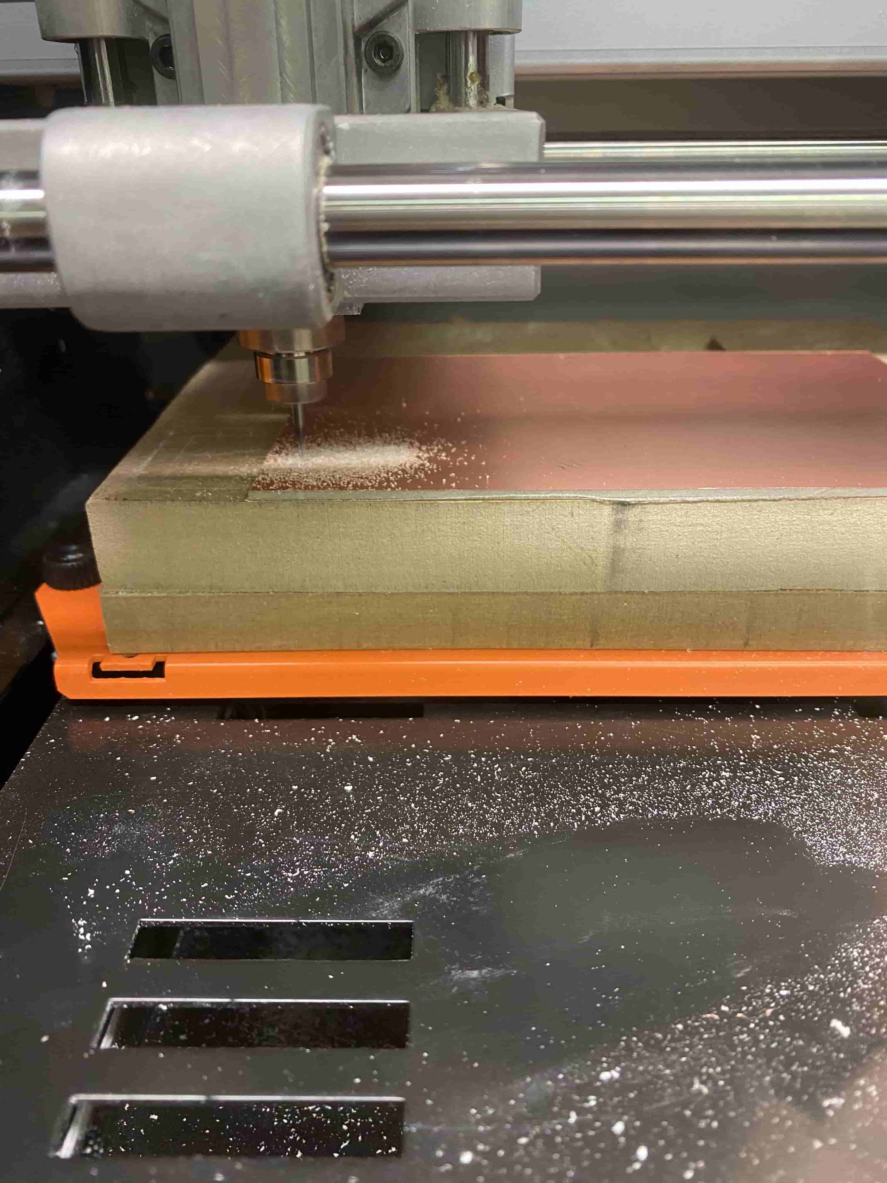
It took me 2 attemps to mill the board out, because I accidentally changed the thickness of the lines from 0.5 mm to 0.5 pt. This caused all the traces to dissapear while milling. However, I have went to Adobe Illustrator and changed the thickness back to 0.5 mm.
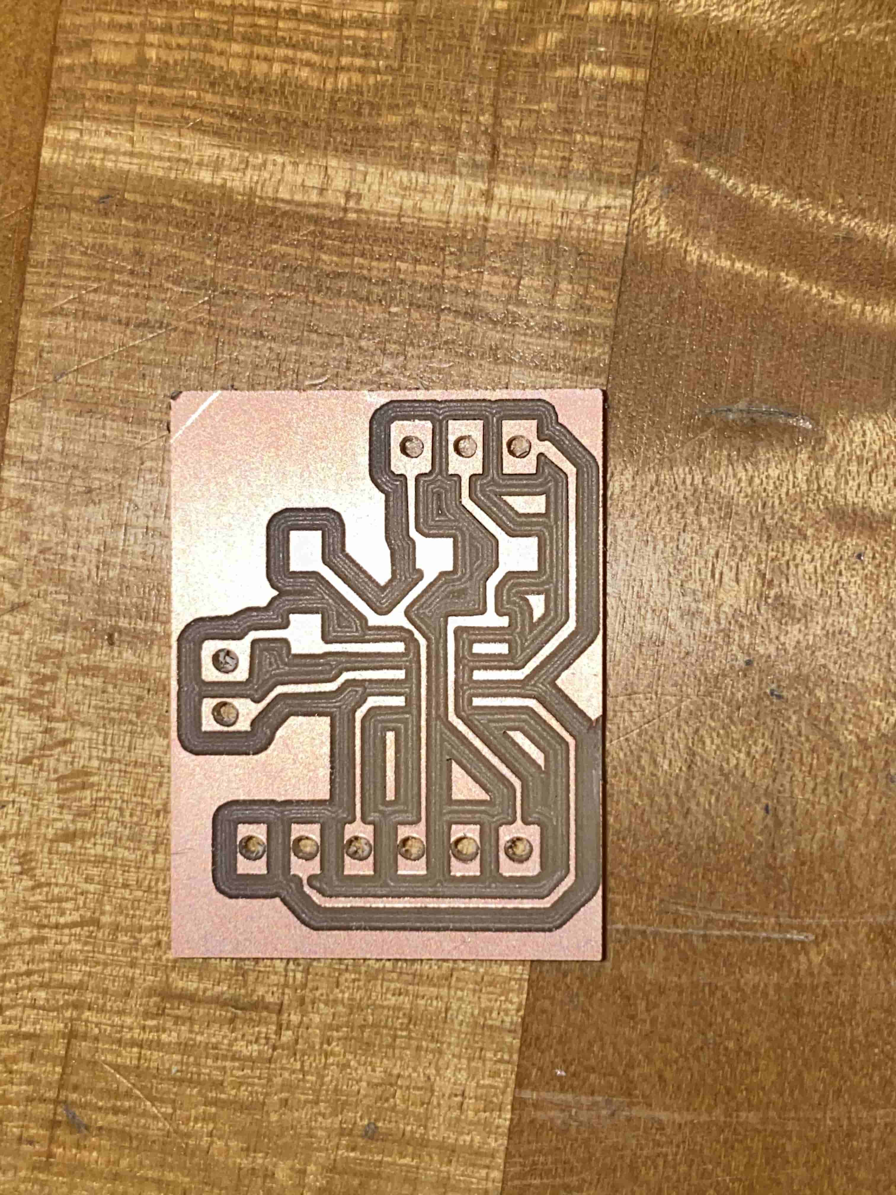
After milling it, the board looked like this. it was as big as my thumb. Using Attiny402 made it so small and compact. This was great because it gave me the idea of not stoping here and 3D printing out a case for my project. I then moved on the soldering the connecters and the SMDs.
Soldering the ATtiny402 was really hard because it was really small and all the copper wiring was too close to each other. The first time I soldered it, it shorted, Henced, I had to remove it and clean it and then resolder it. I have also soldered the I2C adapter to the LCD so that they will take less space and it will be more solid. While soldering my own board, I have started soldering with the pins. The reason I did this is because I wanted to use solder wire to solder the connectors. This would allow me to solder the SMDs using the solder paste and the solder for the connectors would still be solid.
Everything seemed, so pink. I was steps away from completing my Assignment. However, obviously there has to be a problem. The Attiny402 only has 258 bytes of memory, however, my code was 277 bytes. Hence, it was never able to upload.
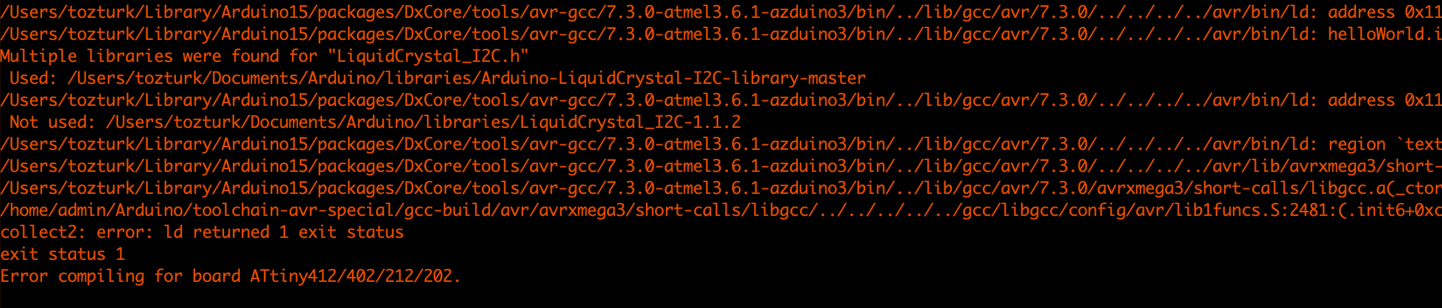
This was the error I got. After reading the code I understood that I was going over the memory limit. Hence, I started optimizing my code but then I realized, I don't need the Serial Monitor part and once I deleted it, my code went from 270 bytes to 158 bytes.
This was the cause of my code not uploading into the ATtiny402. This gave me the idea of uploading a code just for reading the values from the joystick to complete the assignment and one for the game.
this is the code for reading the values from the joystick. As you can see from the Serial Monitor, I am getting different Values as I move the Joystick.
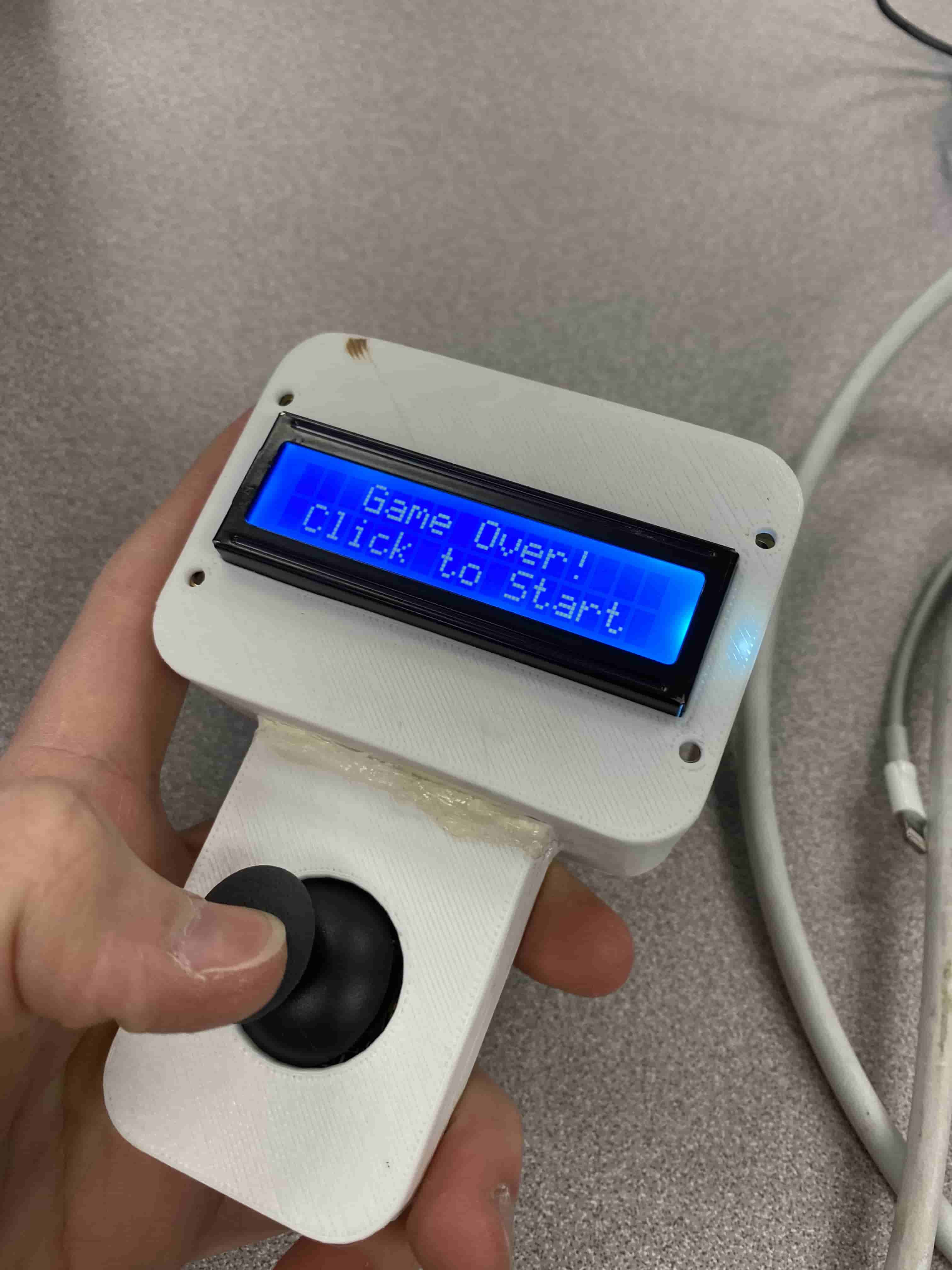
This is me uploading my code to my board and playing it.
At the end I have used a battery to made it portable and playable.
Extras
I also wanted to 3D print a Casing for my board. Hence, on Fusion I have started Designing a casing. to make it look more realistic I have imported the designs of LCD, Joystick and Batteries. At the end it looked like this.
Unfortunatelly while soldering everything together with normal wires rather than using dupont wires, I have burned my board and the joystick. So I had to replace everything and then restart by milling a new board. However, this time when I put everything, the game had some bugs. I think this is because either the cables I connected are touching eachother and shorting some curcuit and making the game act randomly or I burned the microcontroller while I am trying to replace it from my old board to my new board. On top of everything After soldering all the wires and setting up everything. I realized that I forgot to replace the SMD parts t my new board, so I had to put them all to their place while my board is inside my 3D printed PLA casing. Which ended up benting the case a bit and burning my fingers.
Finally it looked like this: