Assignment:
Group Assignment:
1# Measure the power consumption of an output device.
Individual Assignment:
1# Add an output device to a microcontroller board you’ve designed, and program it to do something.
Brainstorm
Softwares:
 - Fusion 360 - A CAD software that allows both 3D and 2D designing
- Vpanel - A CAM software that talks with Roland SRM-20 Desktop mill to send the job
- Fusion 360 - A CAD software that allows both 3D and 2D designing
- Vpanel - A CAM software that talks with Roland SRM-20 Desktop mill to send the job
 - MIT Mods - a great software that allows CAM software for multiple devices at the same time
 - Adobe Illustrator - a great software that allows editing and manipulating vector images
Machines:
 The Arduino UNO is the best board to get started with electronics and coding.
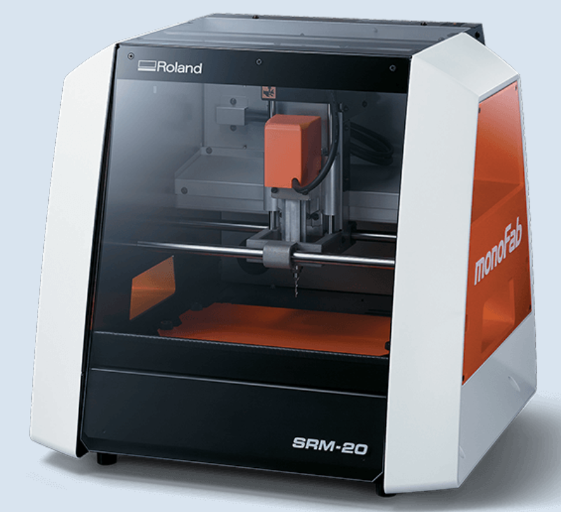 Roland SRM-20 - it is a precision mill that can hold variaty of small endmills ranging from 0.3mm to 6mmm diameter endmills
Tutorials:
Group Assignemnt
For this weeks group assignment we have worked on learning what kind of output devices we have and how much power each output device consumes during regular usage and high load usage. Initially, we used an AA battery pack of 4. This provided us with 6V of potential difference in our circuit. We used a multimeter to check this:
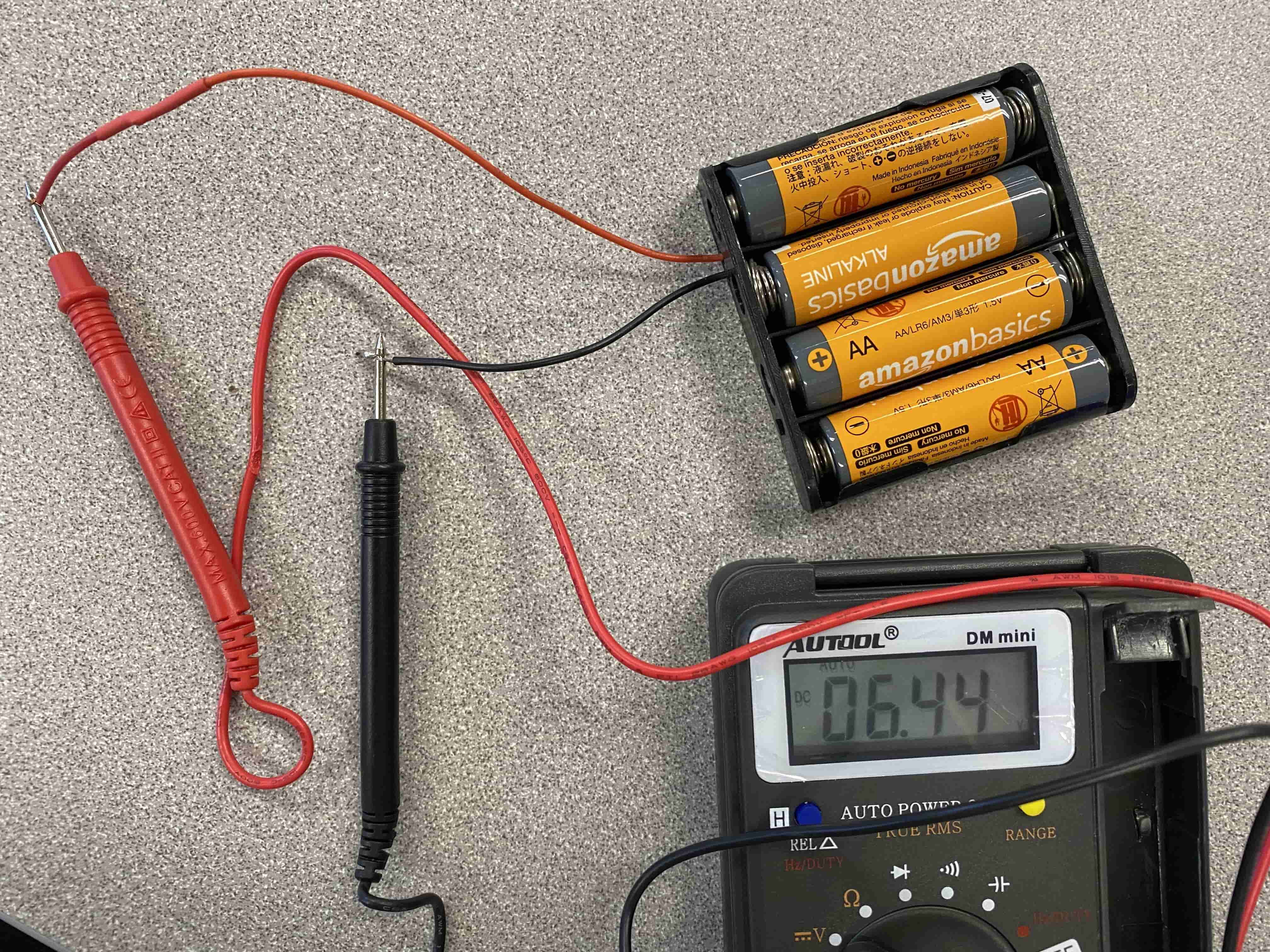
After we checked our batteries, we got a number around 6 Volts. We then attached a motor to it:
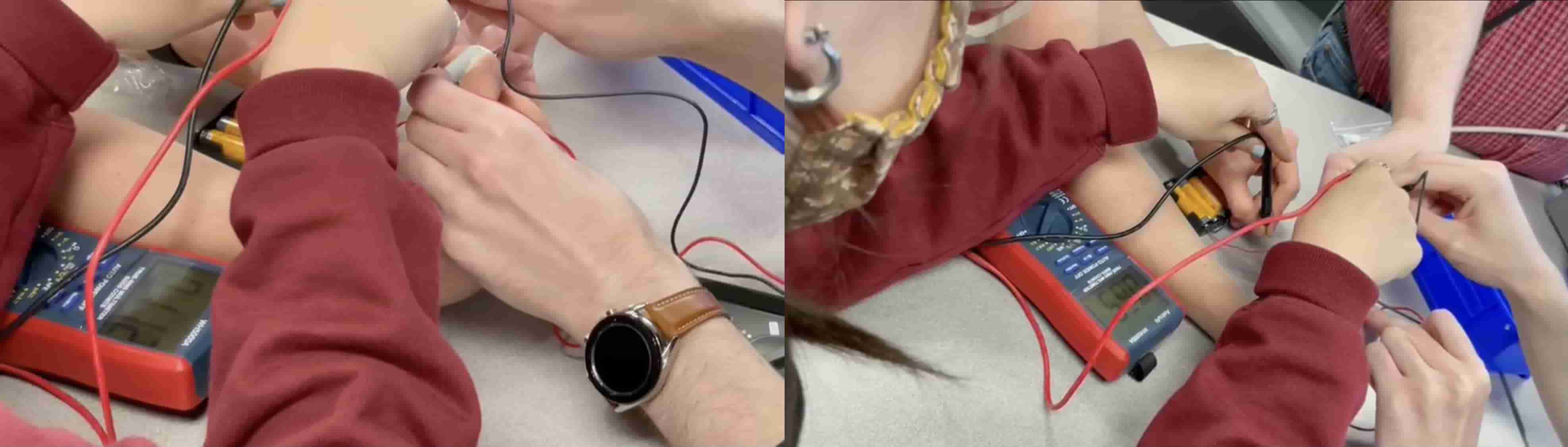
At first we check the current and the voltage through the motor. The Current stayed as 6 V because the motor was the only component on the circuit other than the battery itself and the Current was around 0.1 Amps. However, Once we hold the shaft of the motor and stop the rotation. This increased the current to around 0.85 Amps. When we check the specifications of this motor, it also said that if hte shaft is stuck the current will spike to 0.8 Amps.
Then we moved on to learning how to use analogueWrite and analogue pins. We learned about how analogue pins can give out signals in a specific frequency. We also learned that this is because an MCU cannot change the voltage of its pins but can change the frequency of on and off in the pin to simulate a decrease in Voltage.
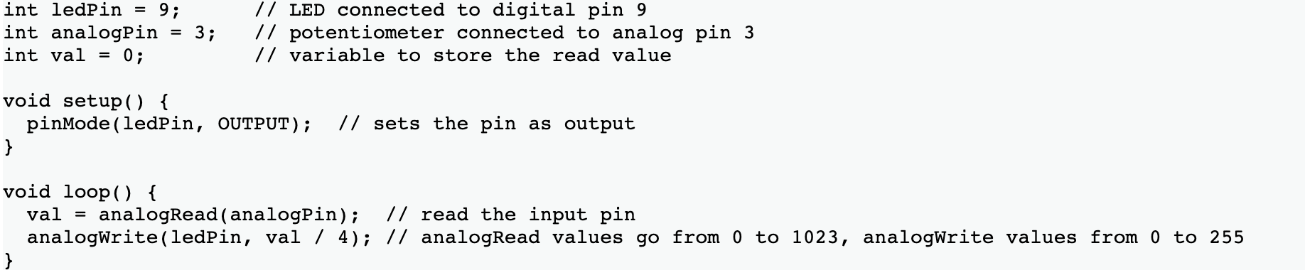
The first parameter in analogueWrite represents the analogue pin that will be the analogue output pin and the second parameter is the frequency from 0 to 255. The number 255 comes from 8-bit MCU system. 8-bit system means 2^8-1 = 256-1 = 255 bytes and this is because bytes starts from 0.
Using an arduino we were able to increase the brightness of an LED.
As you can see, I wrote a code that increases the frequency every 0.1 second. The frequency in AnalugeWrite works as a percentage of the time where the pin is on and off. If the AnalogWrite is 255 then that means the pin is always HIGH. If the AnalogWrite is 128 then it is only 50% of the time HIGH.
to better visualize this we used an ossiloscope and a more static code which only lights up an LED at 50% power. We saw that the the Ossiloscope was going from 0 to 5 volts every 1 ms.
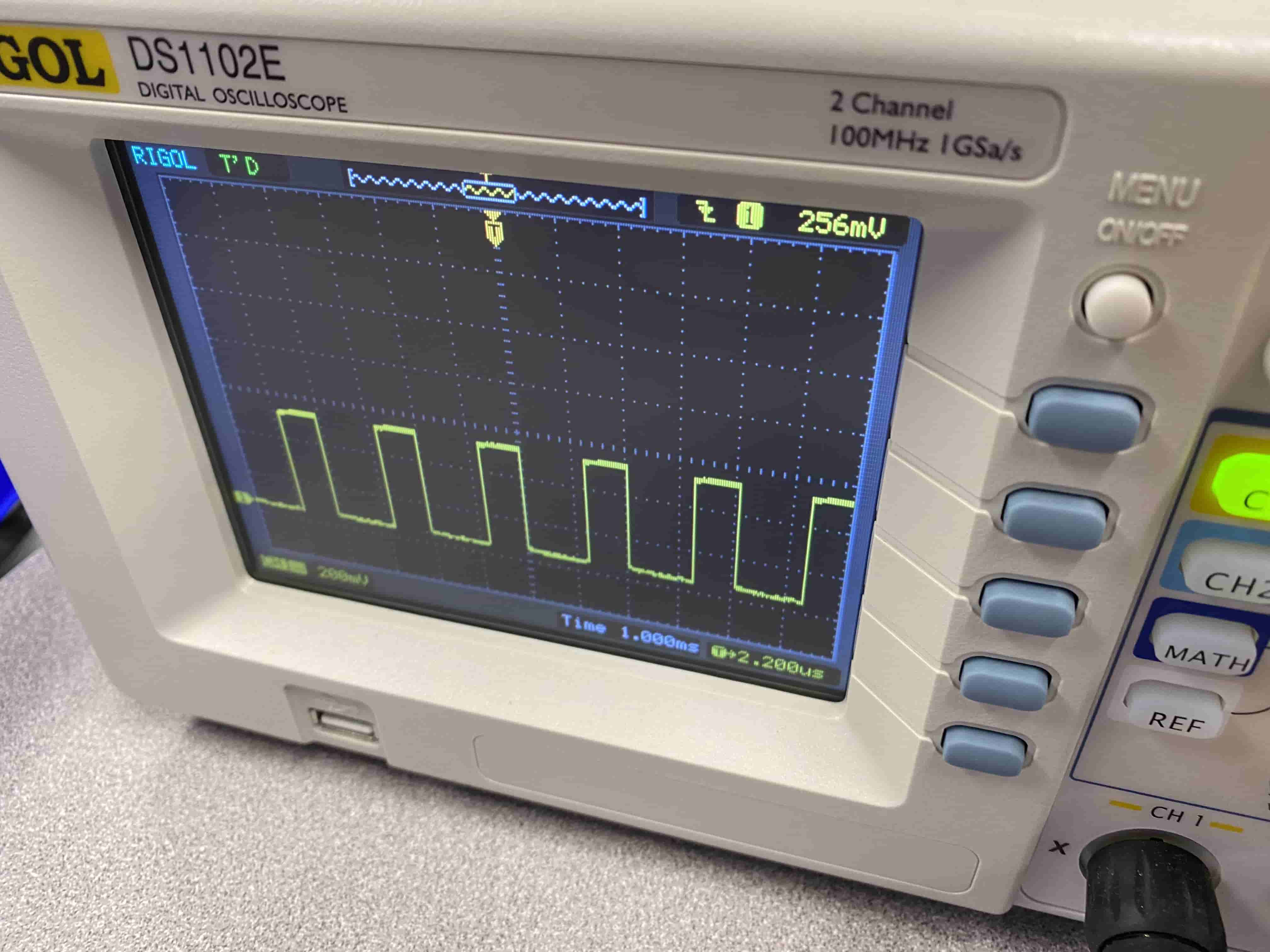
As you can see we have high every 1 ms rather than a continues HIGH signal.
Individual Assignment
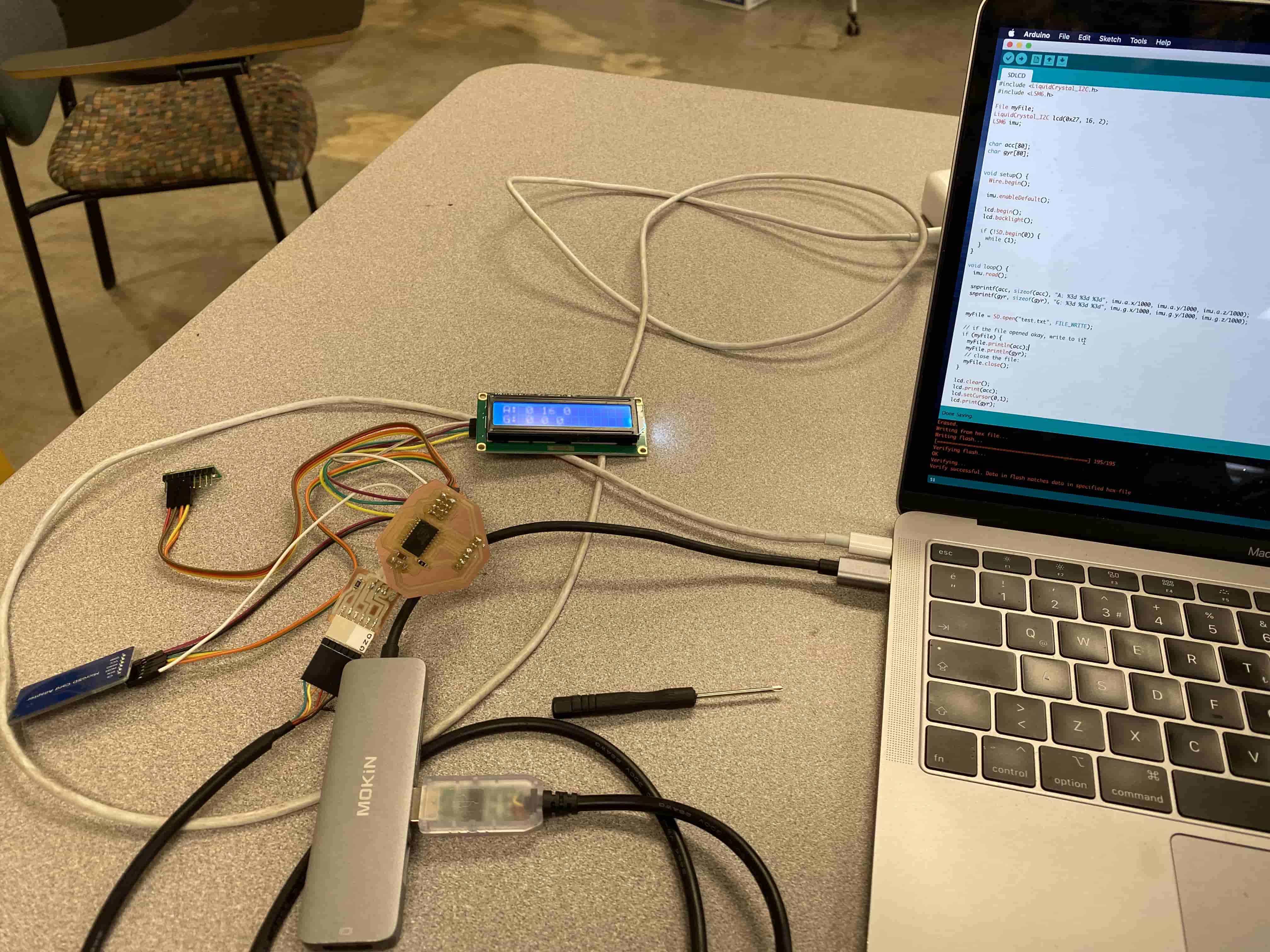
For my individual assignment, I wanted to do something different and more useful. So I decided that I am going to use an Accelerometer & Gyrometer to display values on an LCD Display while storing the data gathered to an SD card. At first I was worried that it wasn't going to work, because both the Accelerometer and LCD display uses I2C connection and I didn't know that you can connect more than one devices to the same I2C pins and use them at the same time. That is why, I first constructed my project on a breadboard first and then tried to run it using an Arduino Uno. Unfortunatelly, while I was building a basic gameboy for Input Devices Week, I have wasted an LCD display with I2C module, so I had to fix that one before using it. After fixing it, I have connected it to the breadboard with all the other devices. For the SD card, I have done some prior research and experimentation, so I knew how to use it but I accidentally connected the Ground to VCC and made the SD card reader module go so hot that it kinda burnt my fingers. After fixing all the problems, I set up the breadboard and flashed the Arduino Uno and it worked.
After having the Arduino work, I went on to kiCAD and started designing my board. Unfortunately because I was trying to connect 4 things (UPDI/POWER cable, LCD, SD card module, and Accelerometer & Gyroscope) at a time I did not have enough space to do cable management. Hence, I had to use some sketchy tactics and jumper resistors.
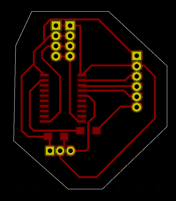
As you can see I had to combine multiple I2C connectors, have some jumper resistor, and mess up with the layout of SD card module pins. I have made this comprimeses just so that it can neatly fit on my board. Unfortunately because we are using Roland SRM-20 Precision mill rather than using modern technics, we cannpt have multiple layers on our boards, which would allows us to have crossing but not intersecting paths.
After designing it I have exported it to Adobe Illustrator as all combined black and White SVG image. In Adobe Illustrator I have seperated it to 3 different layers and did some edits to seclude only the parts I want for each layer, which corresponds to: drill holes, outline, and traces. After that, I have exported each layer as PNG and opened in Mods to convert them into RML files. After completing it, I have uploaded it to Roland SRM-20 Precision Mill.
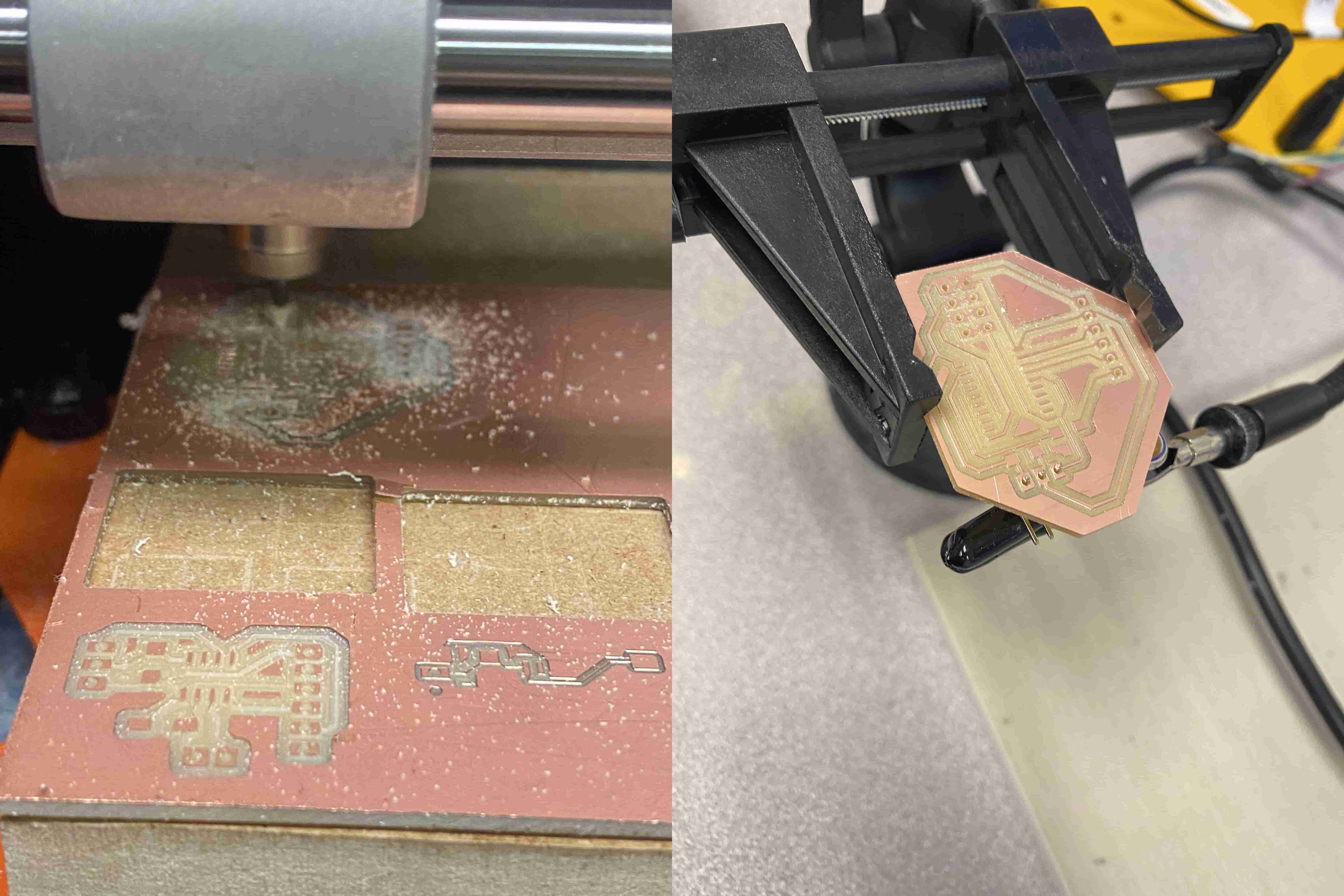
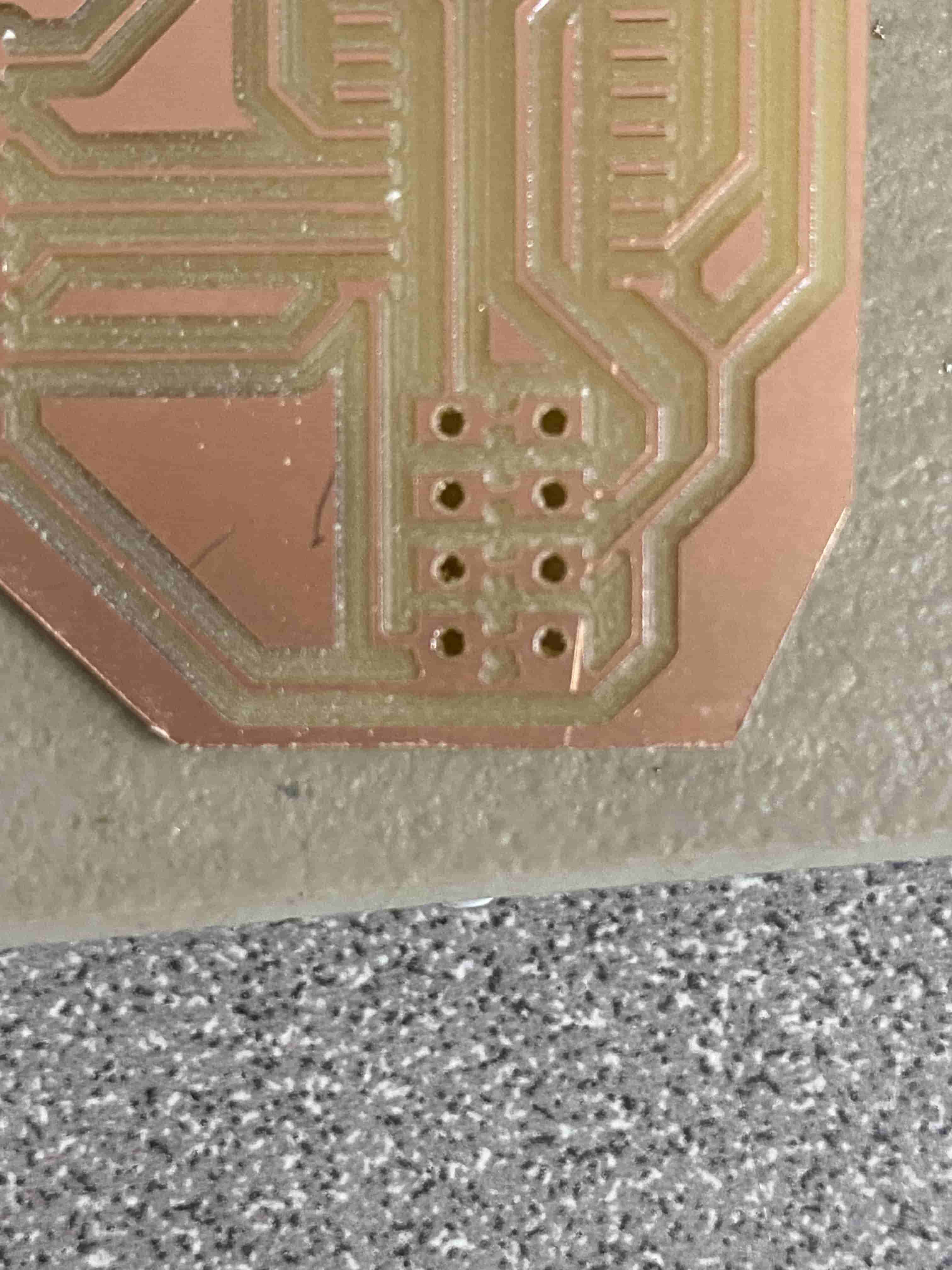
After milling my board, I have started by soldering the header pins first. I have been using this method of soldering the header's first because they are a bit tricky to solder and I can solder them using wire solder which does not melt when I use the heat gun to melt the solder paste. Hence, I can get as clumsy as I want and my pins wont fall apart while I am putting my Surface Mount Components. Unfortunately, Just as I was about to solder my header pins I have realized that my I2C connection Pins are touching the GND wire. Hence, I used a scalpel and started chiiping away material until they disconnected. To check if it was still connected or not, I used the continuity mode in the Multimeter.
After solving that issue I have soldered everything on and tried to flash my Attiny1616. However, it did not work. Fortunatelly, I also had this same problem last time when I was working on the input devices week assignment and because I started learning assembly I was able to read the error message and understand.
below is my code and the error message I got:
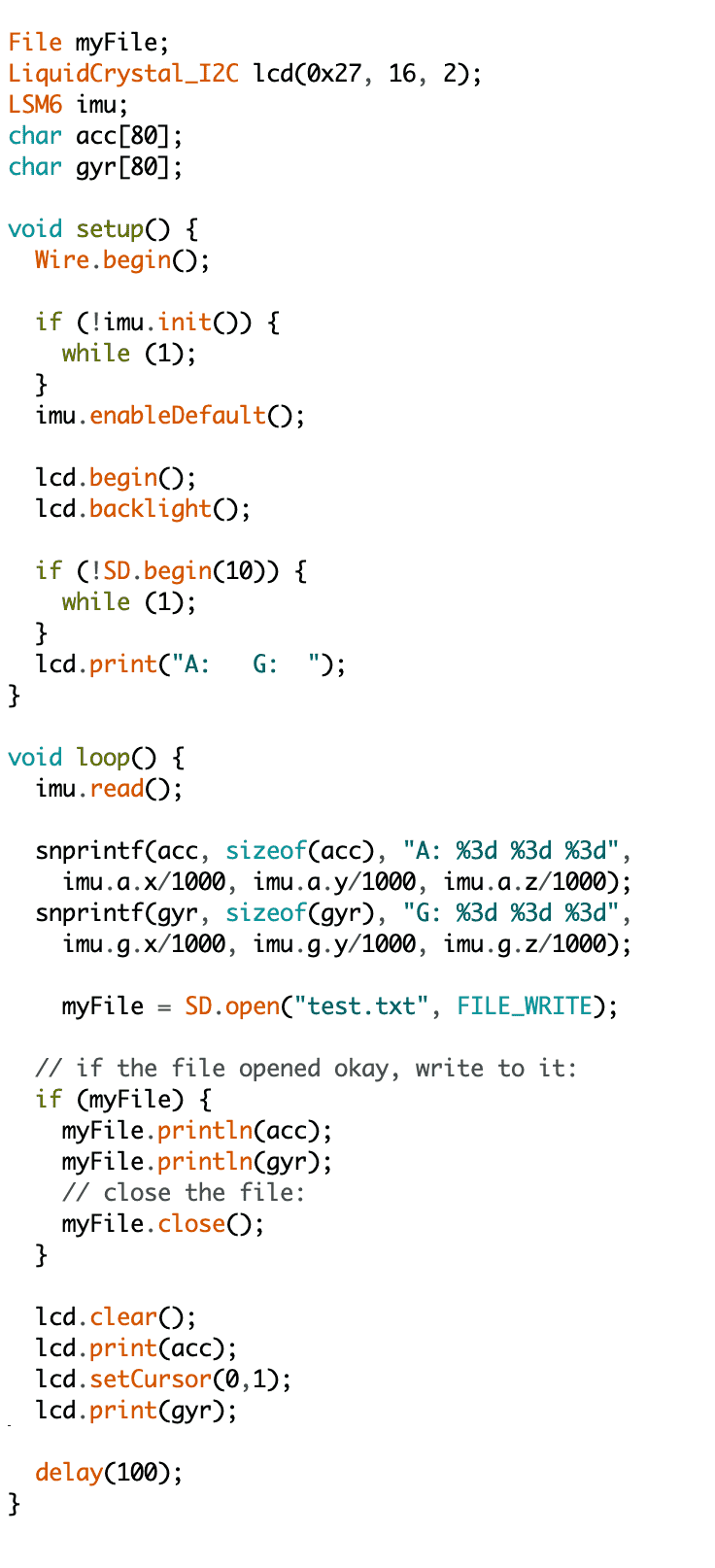
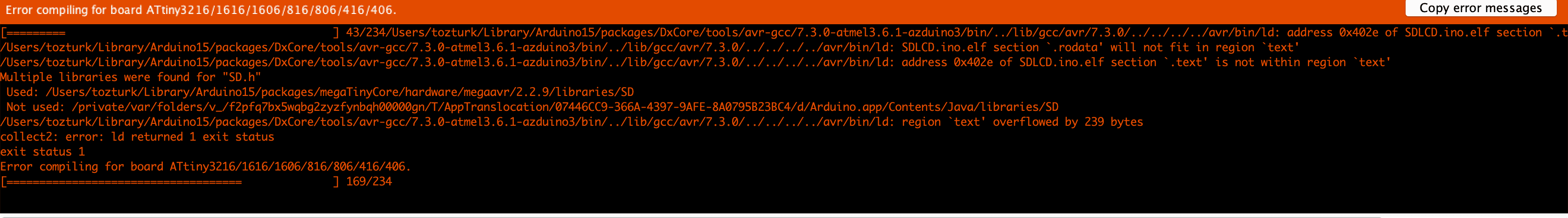
As you can see it says "region 'text' overflowed by 239 bytes" in assembly section .text is the section where the code lays. Hence, this error message is saying that the code itself not the variables but the code itself is too big to fit in the flash memory. To solve this issue I started commenting out portions of the code until I find the main problem. The main problem was the snprintf function that takes a char array and a format and some inputs and fills up the char array accordingly. This is a really useful tool but I figured out that we can do a similar thing using Strings. So I went around that code by trying to add the values using String addition.
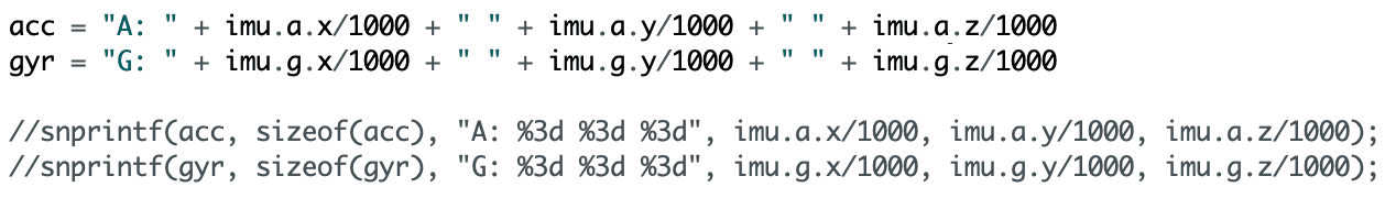
After implementing the code above, it worked and I was able to get an output somewhat similar to what we got with Arduino