Assignment:
Group Assignment:
1# Use the test equipment in your lab to observe the operation of a microcontroller circuit board.
Individual Assignment:
1# Redraw the echo hello-world board.
2# Add (at least) a button and LED (with current-limiting resistor)Resistor calculator.
3# Check the design rules, make it, and test it.
4# Extra credit: measure its operation.
5# extra extra credit: simulate its operation.
Brainstorm
Softwares:
 - Fusion 360 - A CAD software that allows both 3D and 2D designing
 - Adobe Illustrator - a great software that allows editing and manipulating vector images
- MIT Mods - a great software that allows CAM software for multiple devices at the same time
- Arduino - it is a great IDE that allows you to compile and upload your program's to different range of microcontrollers
- Adobe Illustrator - a great software that allows editing and manipulating vector images
- MIT Mods - a great software that allows CAM software for multiple devices at the same time
- Arduino - it is a great IDE that allows you to compile and upload your program's to different range of microcontrollers
Machines:
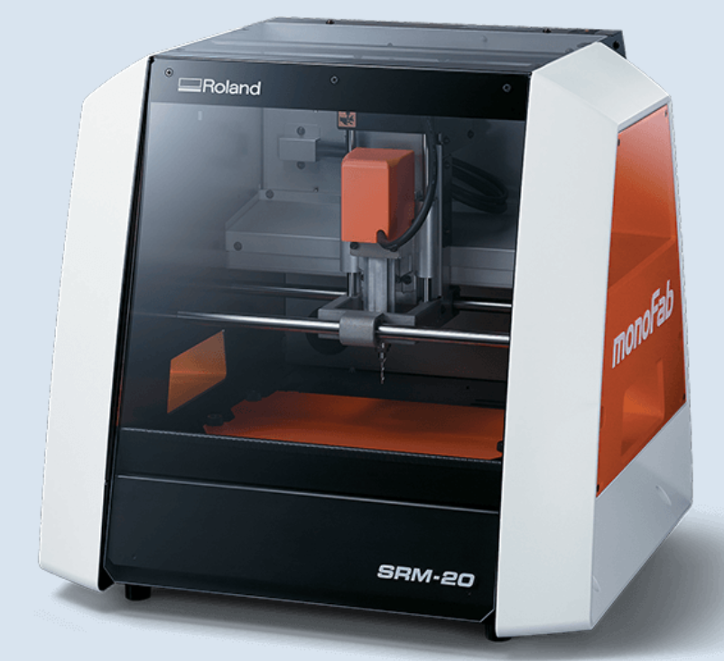 Roland SRM-20 - it is a precision mill that can hold variaty of small endmills ranging from 0.3mm to 6mmm diameter endmills
Group Assignemnt
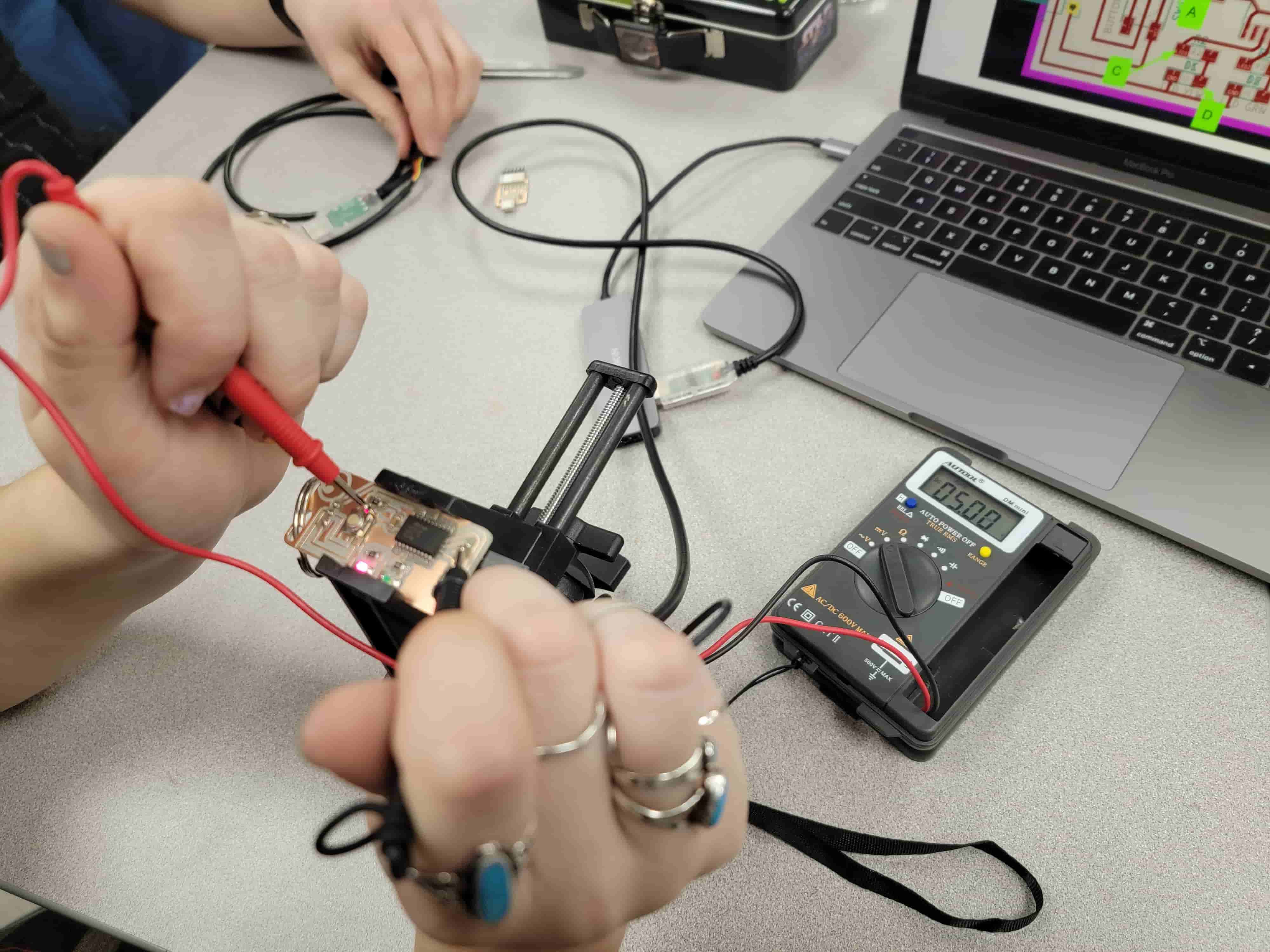
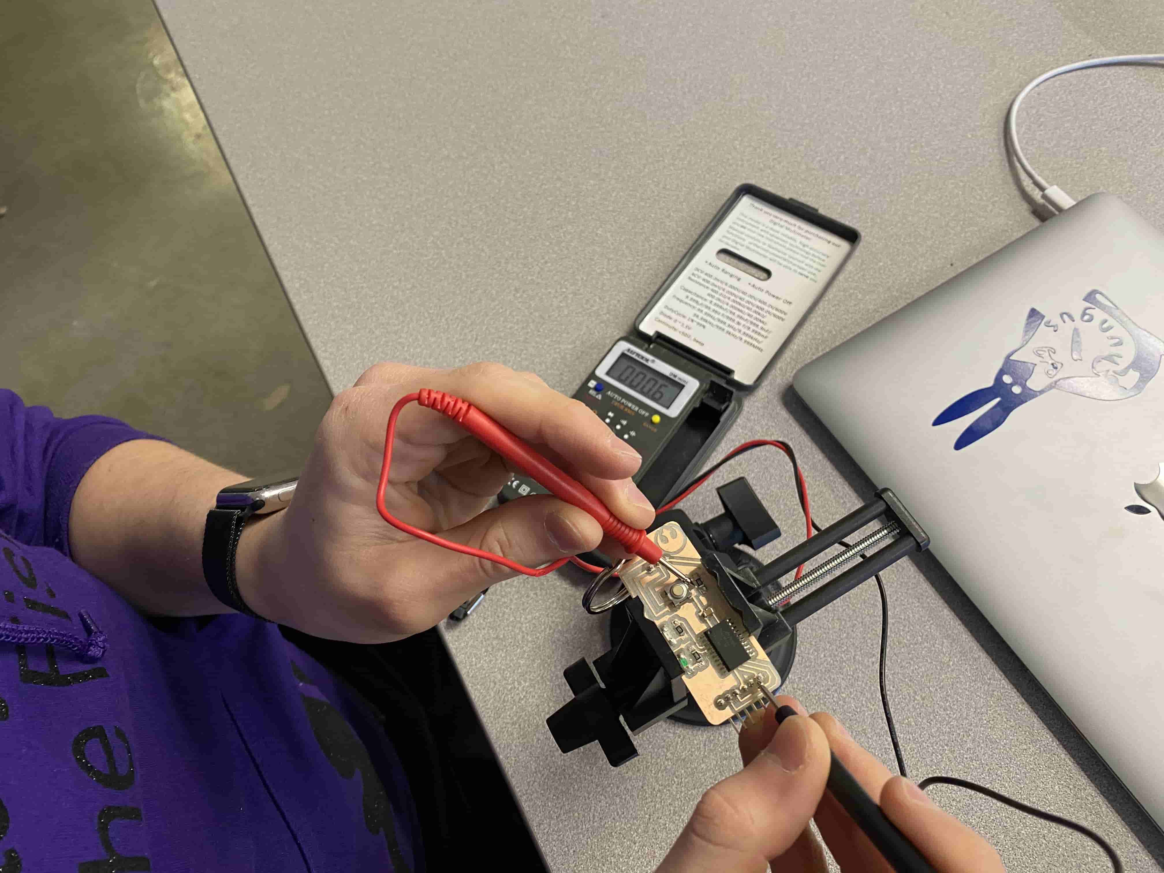
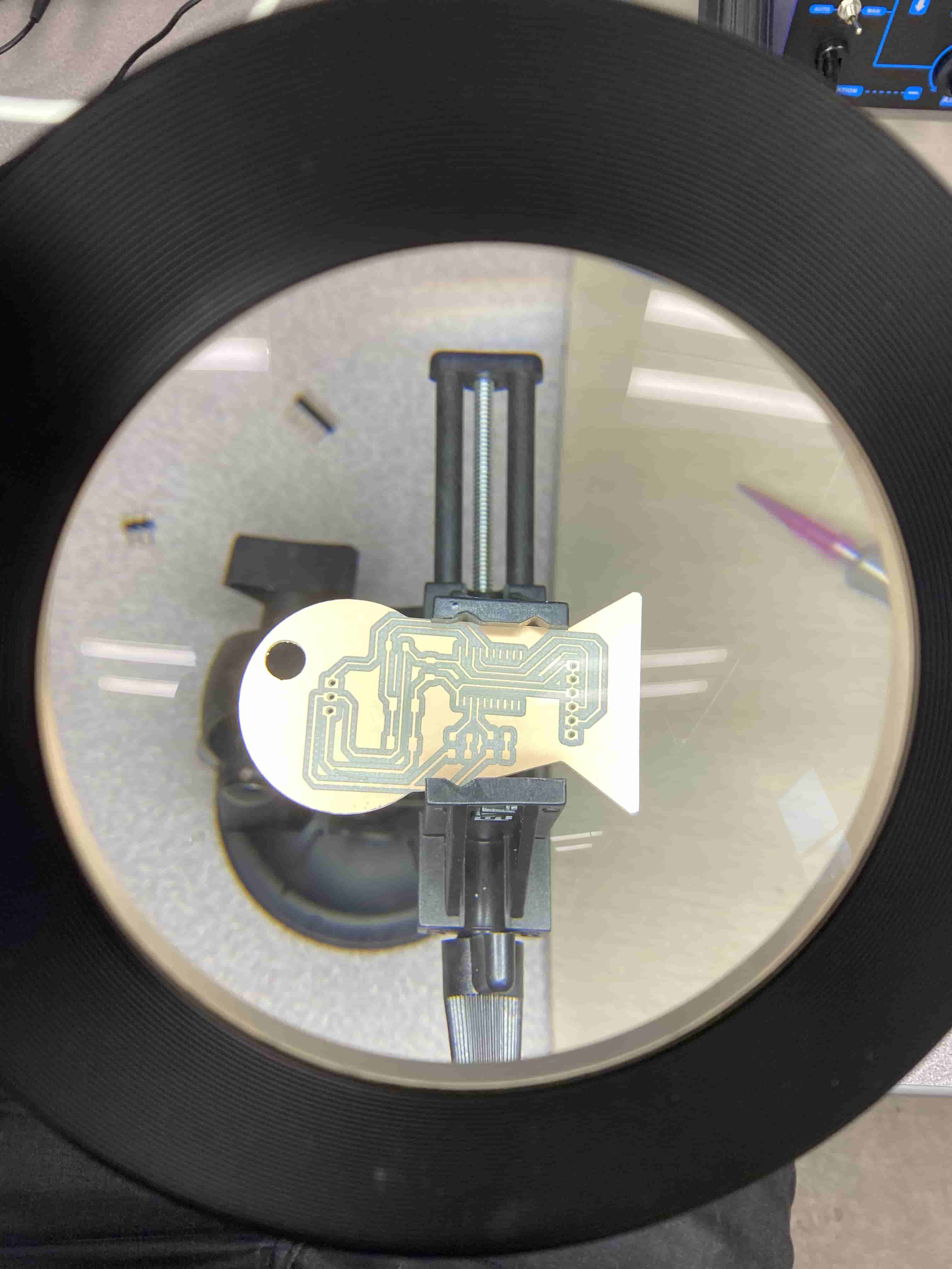
For our group assignment we used a multimeter and an oscilloscope. We used multimeter to check the Voltage, continuity, diodes (or in our case Light Emiting Diodes, LED) and the capacitance of the capacitors. The reason why we used the oscilloscope is to detect if the ATtiny we are using is coommunicating with the computer. Because the ATtiny is talking in a really high frequency it is almost impossible to detect the signals using a multimeter. The signals between the ATtiny and the computer are just a sequence of ones and zeros that can be decifered to become signals and outputs.
For this weeks group assignment we used our teacher's board as an example and used multimeter and oscilloscope on her board. This not only gave an insight on hoow the board worls but also showed us what to do for this week's assignment.
Multimeter Test:
Initially we have tested the Voltagee of the board and learned that the computer sends either 5 volts or 0. and using resistors we can change the current.
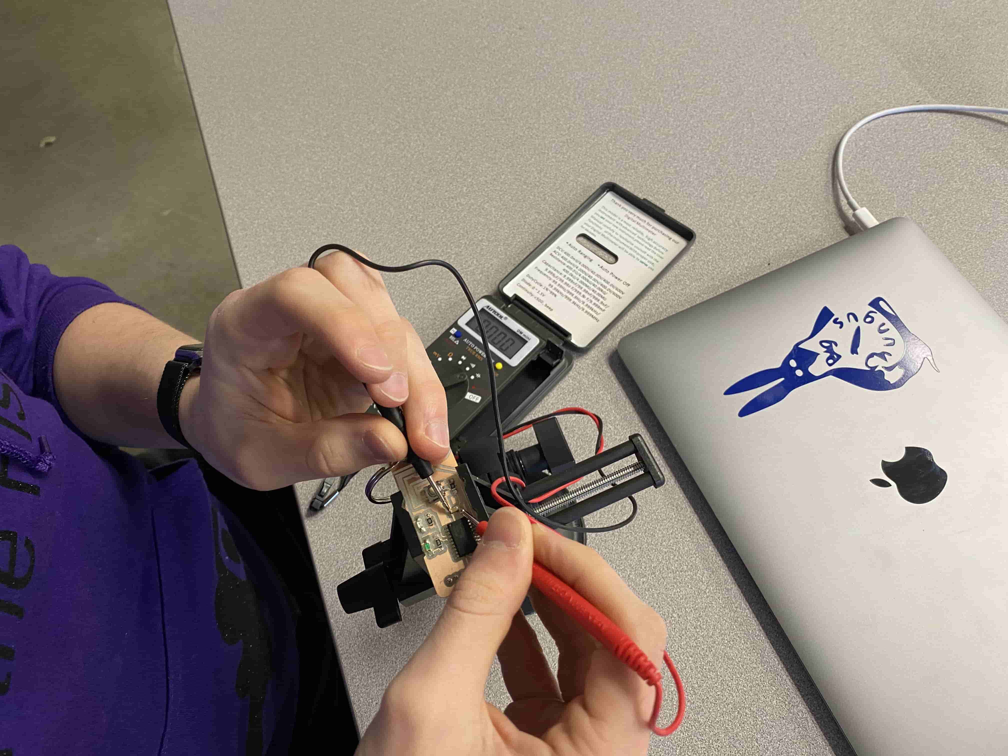
Then we tested the continuation of the board. This test checks if everything is connected as it should be and that there is no breaks on the board or wrong soldered parts. To do this test, we put the negative anchor (cathode) of the multimeter on the grnd pin of the board and then using the positive anchor (anode) we pressed on multiple places that we expected continuous electricity flow without any resistance. If it is true the multimeter would beep, if not then it would show a number corresponding the resistance.
When we did the Continuity Test everything seemed fine. Hence we moved on to diode check test. In this test you can use this for activating the LEDs and checking that they are correctly positioned. Because LEDs are a type of Diodes it is important to place them in correct orientation, otherwise the current will not flow through them and they will not turn on and can even cause bigger mistakes. Hence we checked the LEDs using the Diode check test on the Multimeter and they were all correctly positioned.
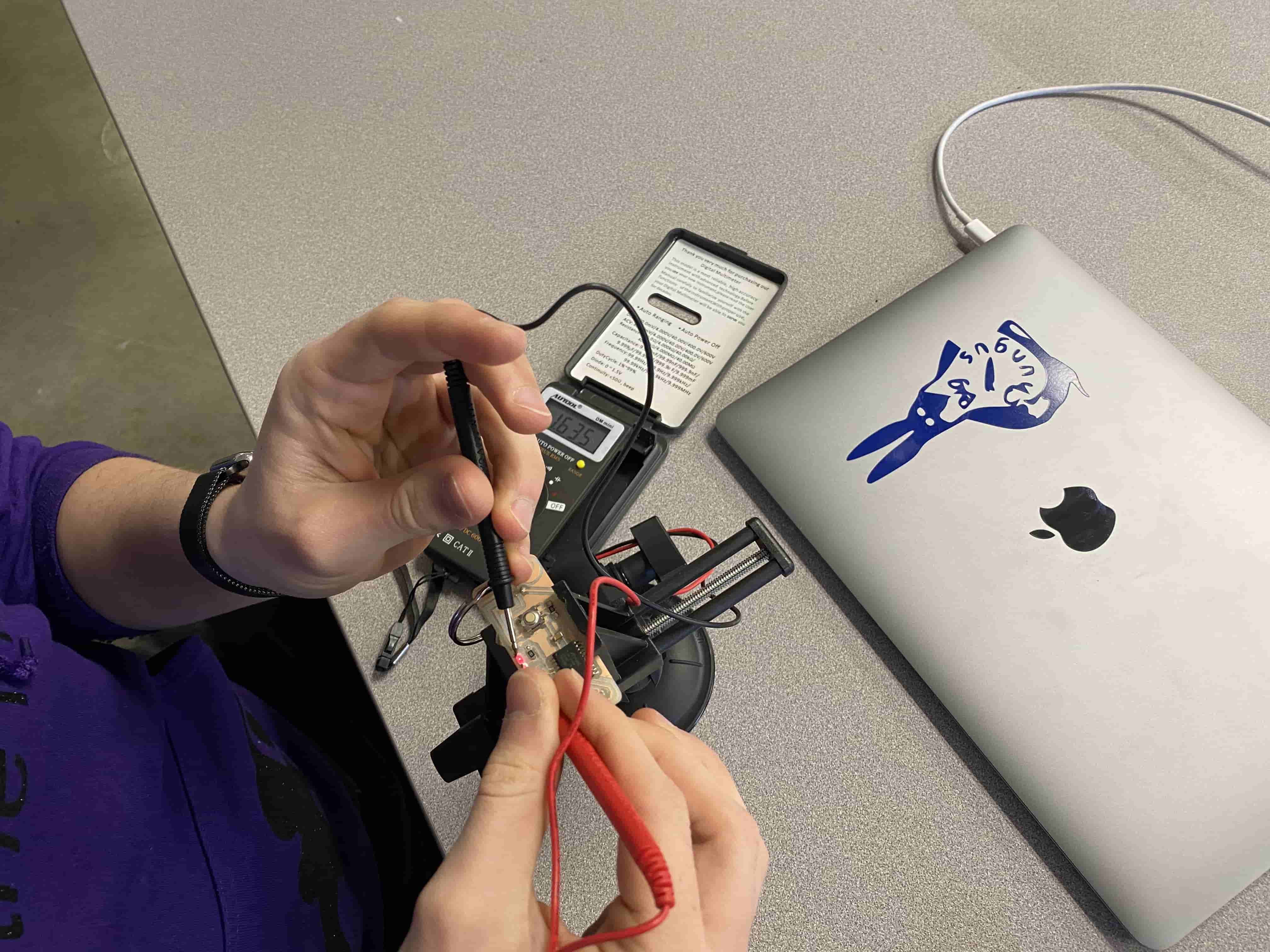
Apart from using the Diode Test on the multimeter it is important to use the Ohm's Law to check the resistance used for the LEDs. This is because different colored LED's require different currents and because the Computer and the ATtiny can only supply either 5 volts or 0 volts you need to change your resistance to get the desired current at the LED. Hence, using Ohm's Law, I have calculated that I would need to use a 1 kOhm resistor for Red LED and 499 Ohms for Green LED.
Finally using the Capacitance Test, we have checked the capacitance of the capacitor used on the board which turned out to my 1 mircoFaraday at.
Oscilloscope Test:
At first an Oscilloscope can be seen as really complicated and terrifying. Which is not too wrong but not too right also. Once you understand the basics, it becomes really easy to understand. Oscilloscope can give really accurate measurement in current flow. Hence, using an Oscilloscope we can see even the smallest differences that span few micro seconds.
As seen in the GIF above, the oscilloscope shows really sharp ups and downs. Those are the ones and zeros the ATtiny sends to the computer as signal to communicate. There are tims that it stops but that's just because I was not able to hold the cables whithout my hands shaking.
The importance of this test is to check if the pins of the ATtiny are placed correctly or the code for the ATtiny is written corrently.
Individual Assignment
Redesign the echo hello-world board:
Fortunately, Fab Academy already deswigned an echo hello-world board, however, this one does not have an LED nor a button. Hence, I need to redesign it to fit this week's assignment specifications. Unlike week5, I now had the power of designing my own board and that mean I can design my own outline.
I initially checked the Fab Academy's design and found the closest one to what I need. In our Fablab, we have ATtiny 1616. Unfortunately Fab Academy did not design a board for ATtiny 1616 but they did for ATtiny 1614 which is close enough for me to edit it and fit my specifications. Moreover, as seen from the image above (Fab Academy's echoı hello-world board) the connectors (headers) are Surface Mount. Which is another problem for me because in our Fablab we did not have the correct Surface Mount Connectors, instead we had Through Hole Connectors.
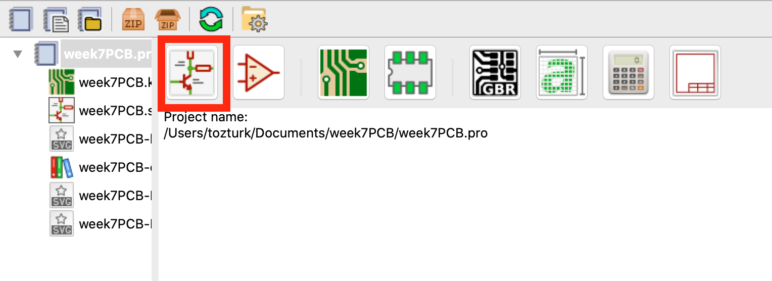
I downloaded KiCAD to design my own board. I initially created a project and started designing by opening the Schemtic Layout Editor. After opening the layout editor, I wanted to add components so I clicked at the "Place Symbol Tool."
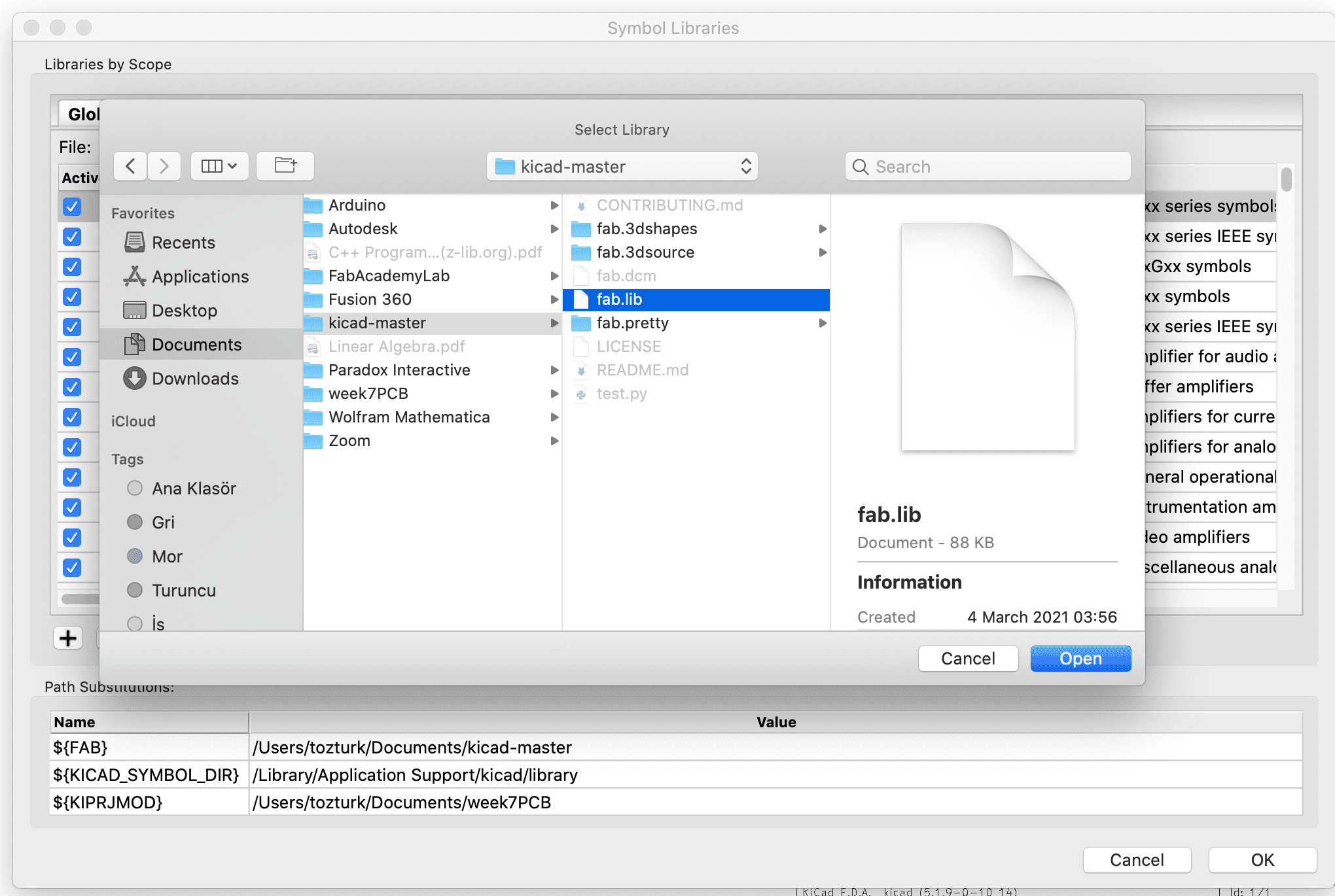
However, I instantly realized that I don't have any of the fab components nor ATtiny 1616 components. Hence I went online and downloaded the libraries for those two.
For Downloading the Symbols of both libraries, I did:
- Go to Schematic Layout Editor
- Go to preferences -> Manage Symbol Libraries.
- Go to Global Libraries -> Click "add existing library to table"

- Select the .lib file from the download folder of those libraries
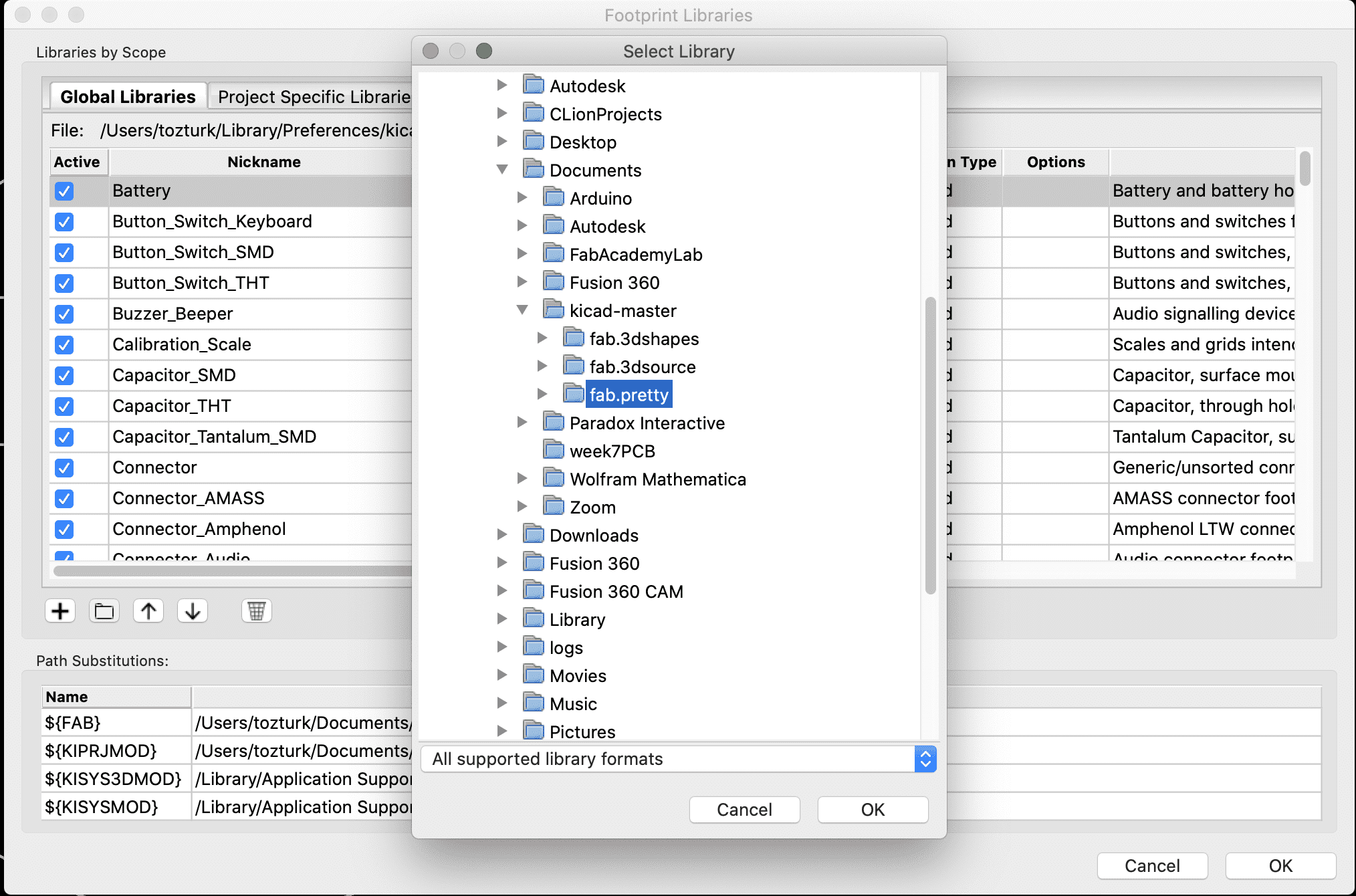
For Downloading the Footprints of both libraries, I did:
- Go to PCB Layout Editor
- Go to preferences -> Manage Footprint Libraries.
- Go to Global Libraries -> Click "add existing library to table"
- Seleect the downloaded folder of the libraries
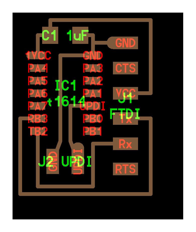
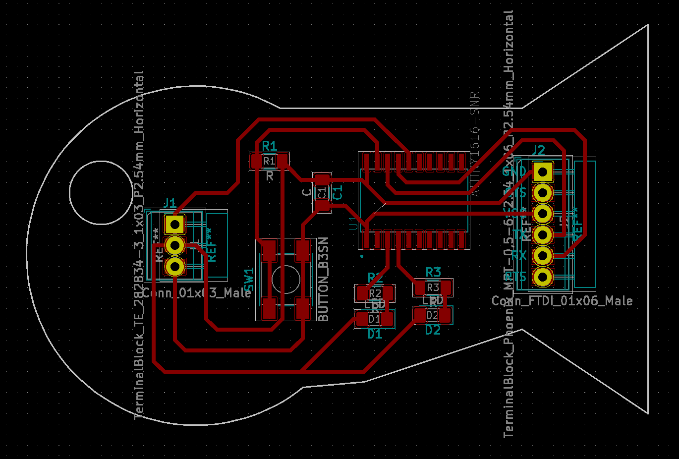
After adding the libraries now I was able to see the components I want, on the Add symbol list. I added an ATtiny 1616, 3 resistors, 1 capacitor, 2 LEDs, 1 button, 1 Connector 01x03 and 1 Connector 01x06. Then I have connected all of them using the Place Wire tool.

Now that I designed the connections of my components, I need to transfer it to the PCB layout editor. Fortunately in the Symbol editor stage the places of the components and the connections does not matter. As you can see there are crossing lines but no junctions. In real life that would be impossible but because this step is only for layout editing and not actually designing your PCB.
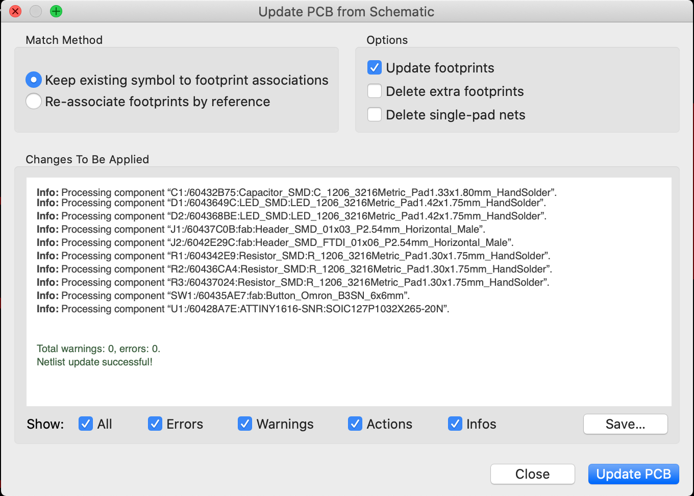
Initially there was nothing, so I click at the "Update PCB from the Schematic" button which takes the Symbols we put in the previous step and then puts their footprint or in other words the actual size and shapes of the parts. This part also allows us to draw actual connections between parts. This means unlike last part, I cannot make intersecting paths if I don't want them to be connected.
However, before even I can start putting the paths down I need to solve the error issue. If we read the error we can see that it is saying that there is no assigned footprint for the symbols we put in the last step. Hence, we need to go back and assign footprints. For this we go back to Schematic Layout Editor and click at "Assign PCB footprints to schematic symbols." After clicking to this button, a menu of footprints and your parts shows up.
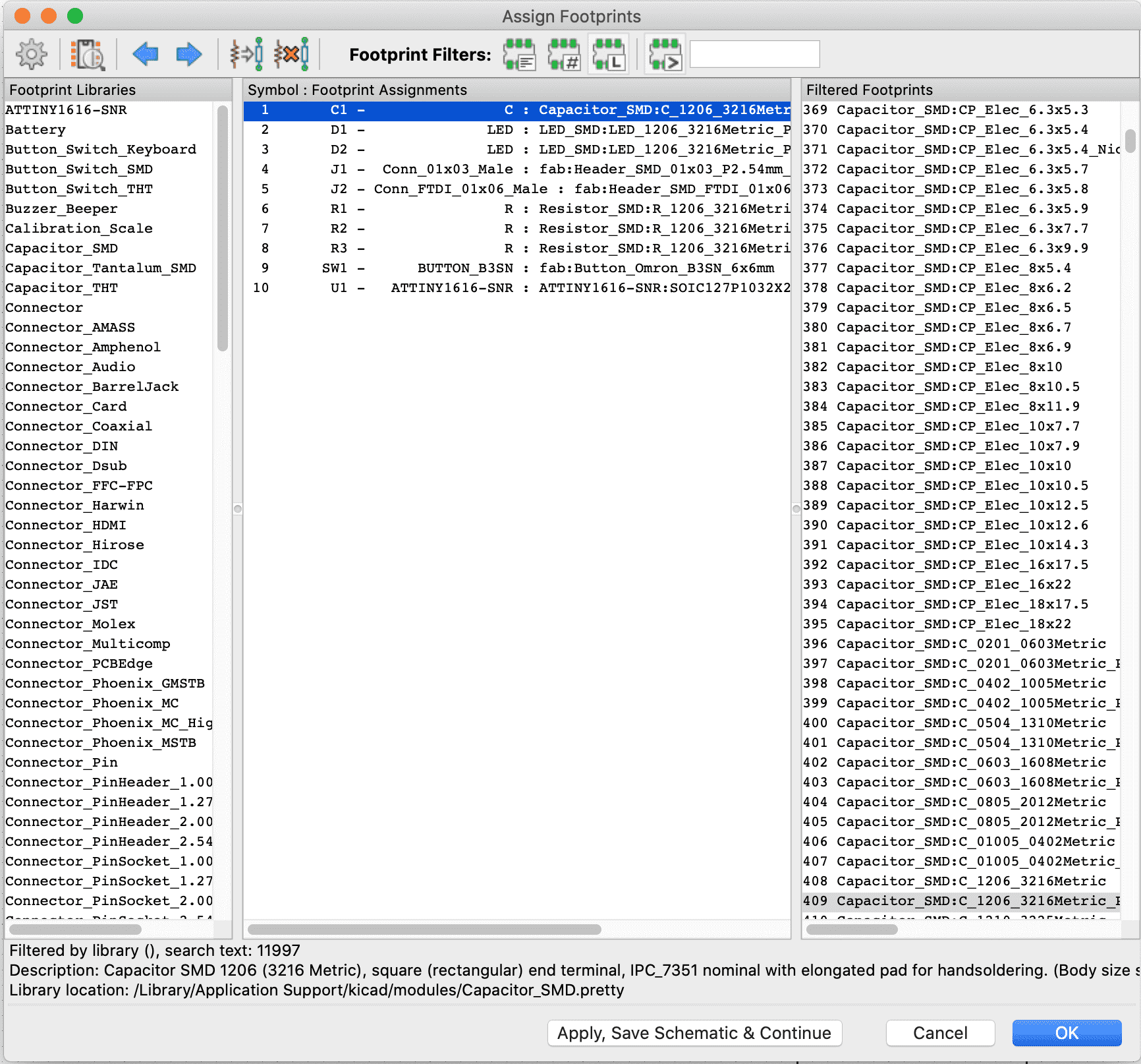
Hence, I need to select each of the parts I created and then select the correct footprint for it. As you can see from the image above, these are the footprints I have selected for my PCB. Then after selecting all of them, we click at update and then click ok. Once this step is finished we can go back to PCB Layout Editor and reclick at "Update PCB from the Schematic" button. Now it does not show any errors.
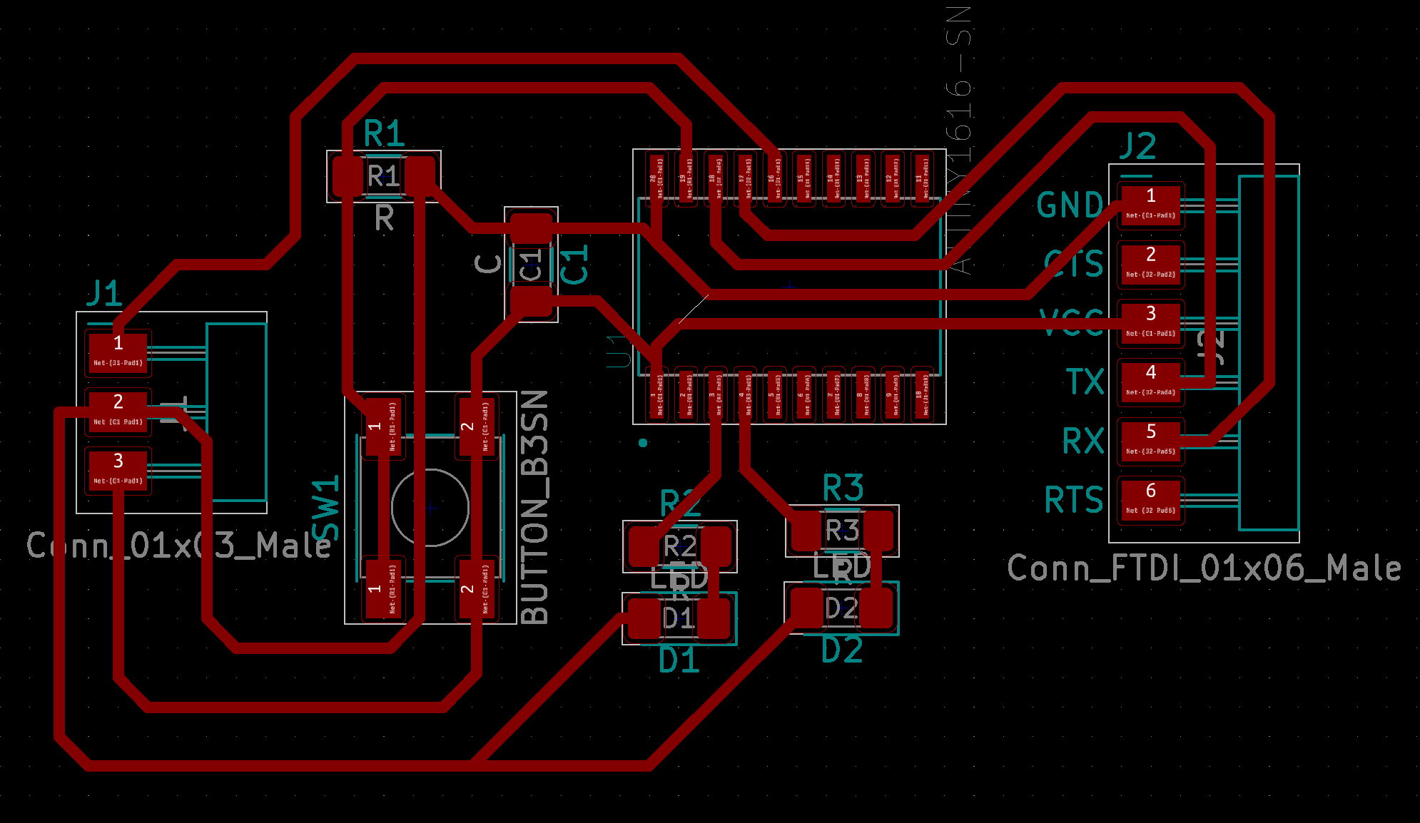
After clicking update and closing the tab we can see that we have all the items. I realigned them and connected them using the "Route Tracks" tool and I got this:
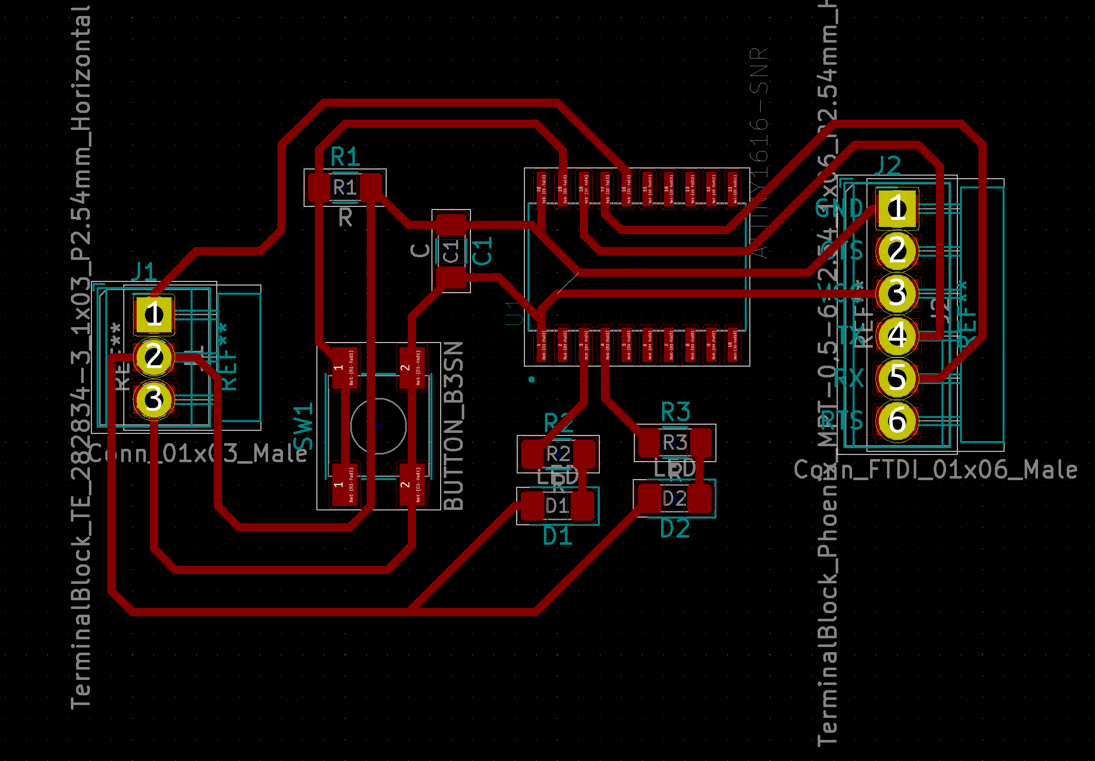
However, I still did not have the holes for the through hole components and I was not able to find them in the part symbol adder tool in the Schematic Layout Editor part. Hence, I went online and found that using the "Add Footprints" tool I can put thee drill holes. I checked the specifications for the part I want to put through the holes and realized that I need 2.54 mm holes. Hence I checked and I was able to find the holes exactly as I wanted. I edited my design again and I got this:
Then I needed an utline for my board so I can cut it out of the PCB after the precision mill finished milling it.
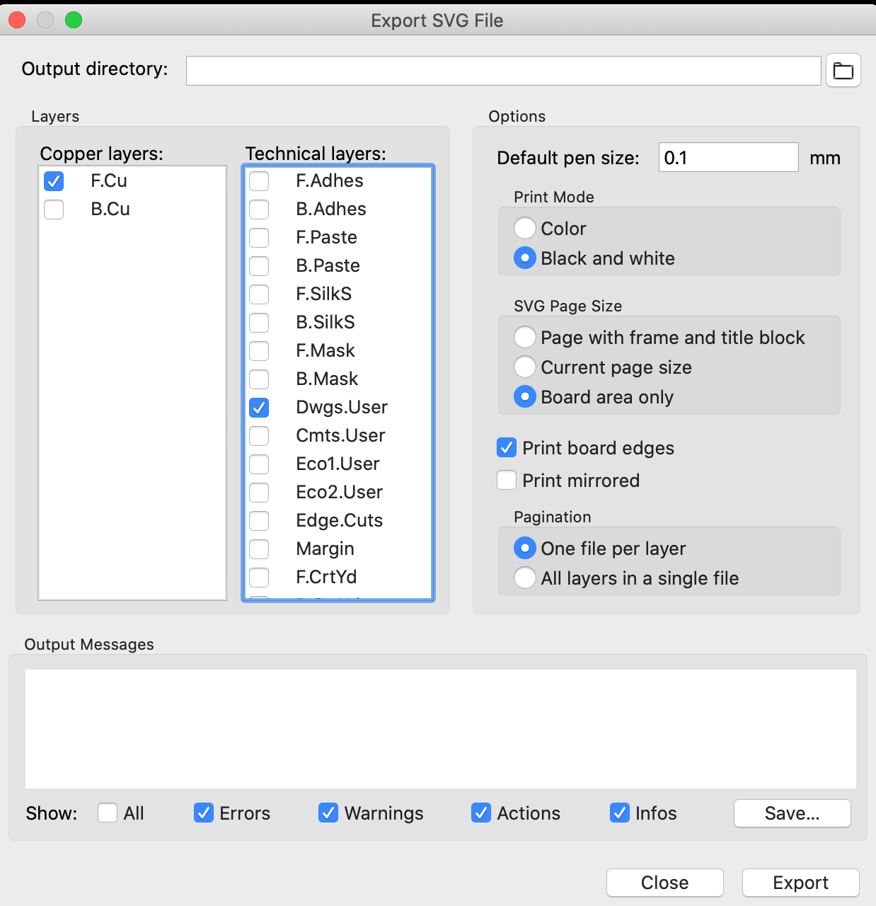
Now that I was done with designing I could export it as SVG and import it at Adobe Illustrator to do some edits. To do this I clicked file -> export -> SVG... This will pop-up a new window where you can select each layer specifically. Becuase I did my designs on F.Cu and Dwgs.User Layers, I only export them 2. I exported them in black and white in seperate files and one where they are together.
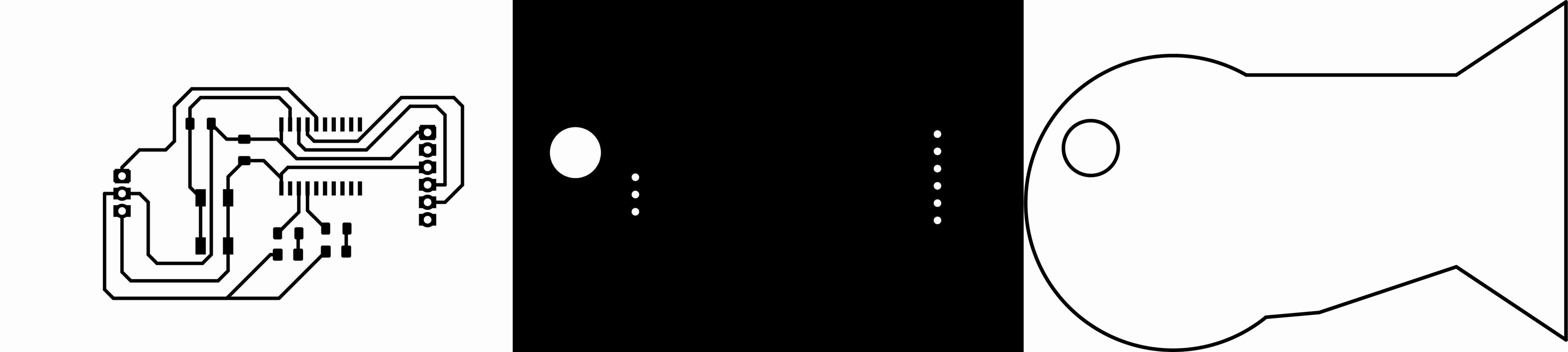
Once, I have the SVG files they looked like this:


Now that I have my SVG files, I can export them to Adobe Illustrator and turn them to the shapes I want. I wanted to add my name on thee PCB too but I forgot to do it. Because the origin point on the Rolan SRM20 Precision mill is the bottom left corneer I made sure that my images are aligned on the bottom left corener then I have created one where there are only holes and the rest is black one with only the outline and one with only the traces. This allowed me to have 3 seperate runs that I can cut one by one. Hence, I can cut the traces first with a different endmill and then cut the holes and the outline with a different endmill.
After uploading it to the mods and running it I have realized that I was getting a missalignment because when I export my images as PNG from Adobe Illustrator, It cut out all the empty space and made my traces go outside the image boundaries which caused missing lines on Mods. I have fixed this by adding a white rectangle behind my trtaces and outline in the same size as the Artbounds.
Then I have gone to Mods and Uploaded my images and followed the same steps I done in assignment for week5. I have created 3 seperate files: one for the traces, one for the holes and one for the outline. Then I uploaded them to the Roland SRM-20 Precision mill. The traces came out really good, hence without changing the origin I moved on to doing the holes. However, when I tried to do the holes, instead of creating a small hole, the precision mill went in and started rotating which destroyed my whole board. I then later realized that because I did not invert my image at Mods, it was following the outline of the white space. So I inverted the image and the the size of the holes on mods got way smaller which proved to be the correct size.
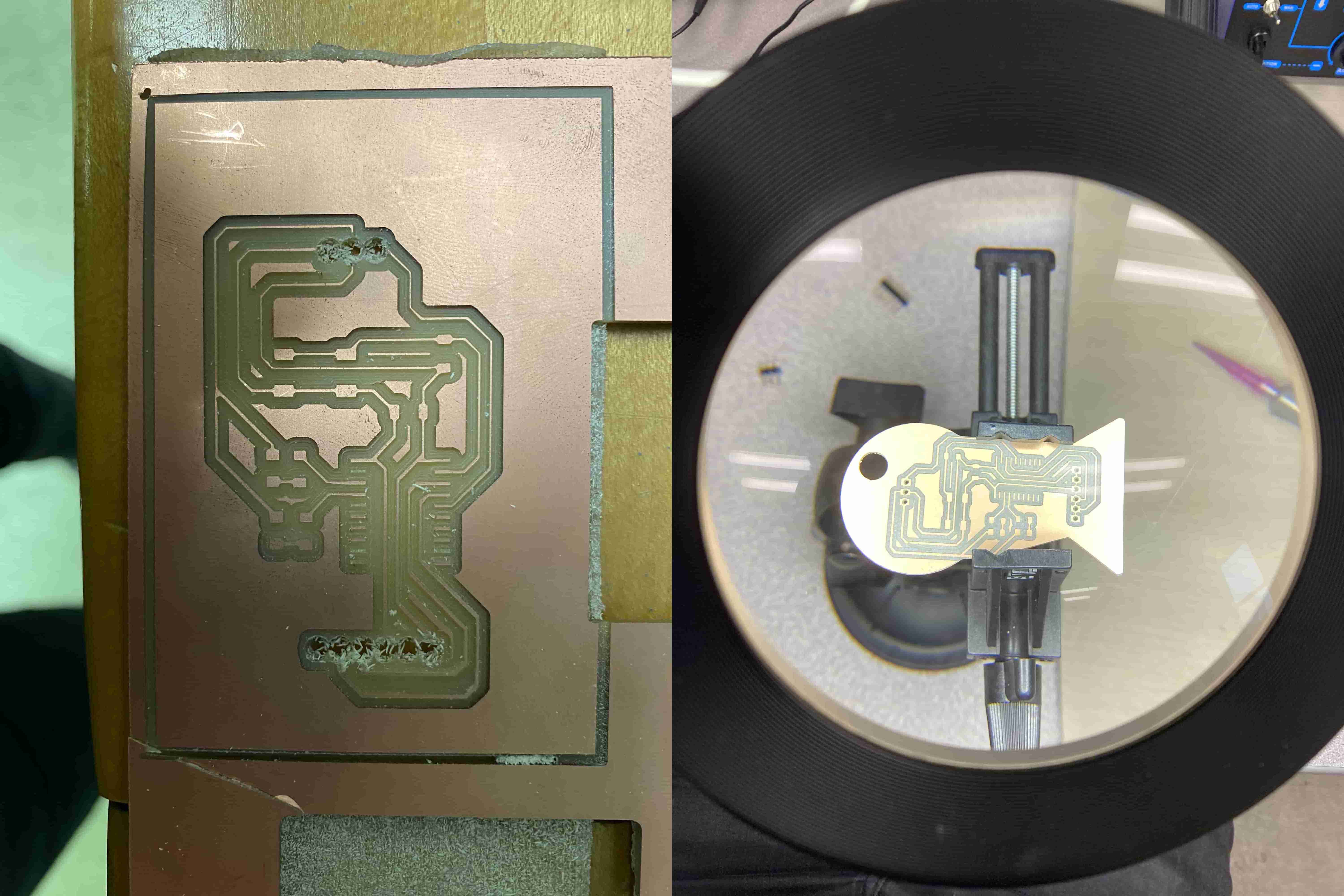
In the image above we can see my first attemp and my second attemp. I also realized that in my image file I put in mods has a black outline which I do not know the reason for. But I solved it by cropping the PNG image after I exported it from the Adobe Illustrator.
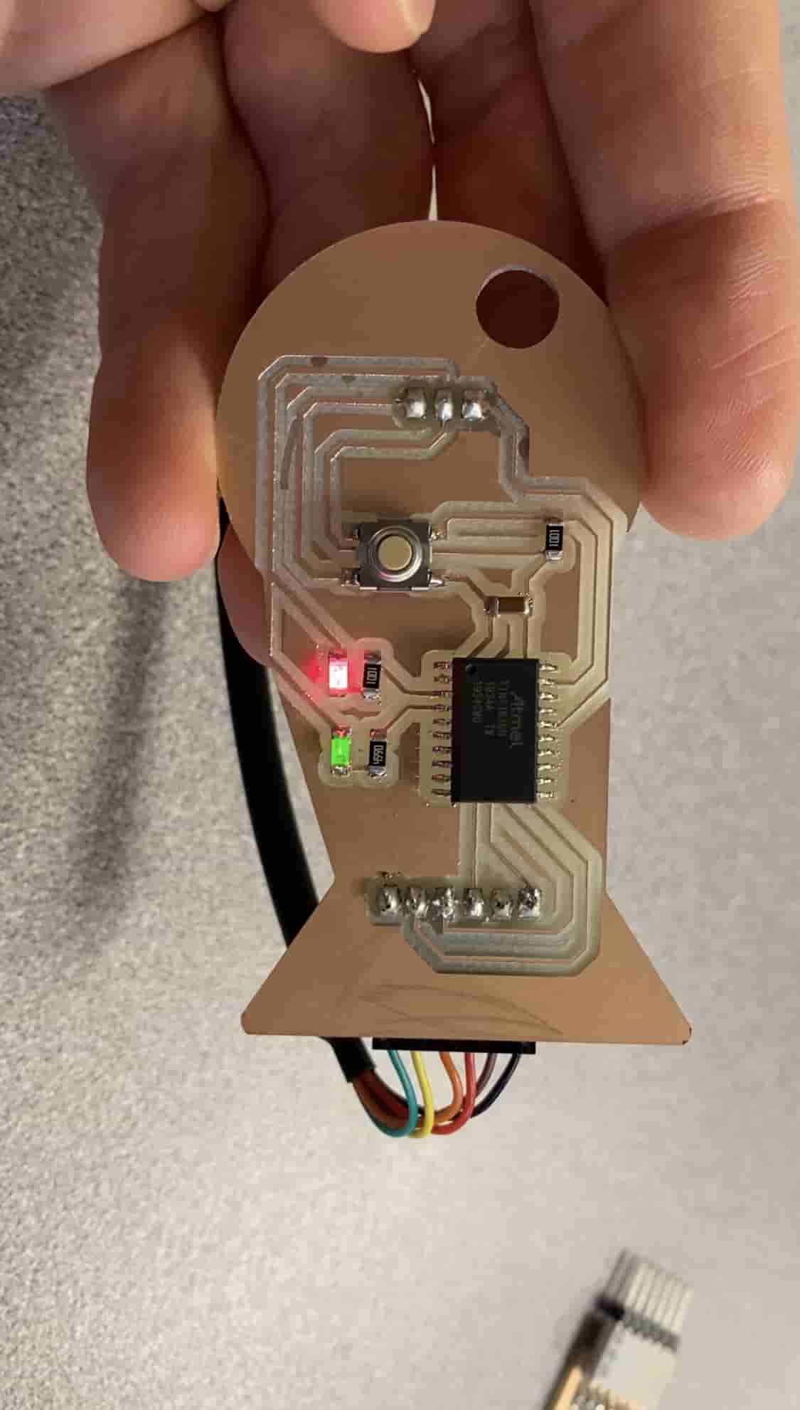
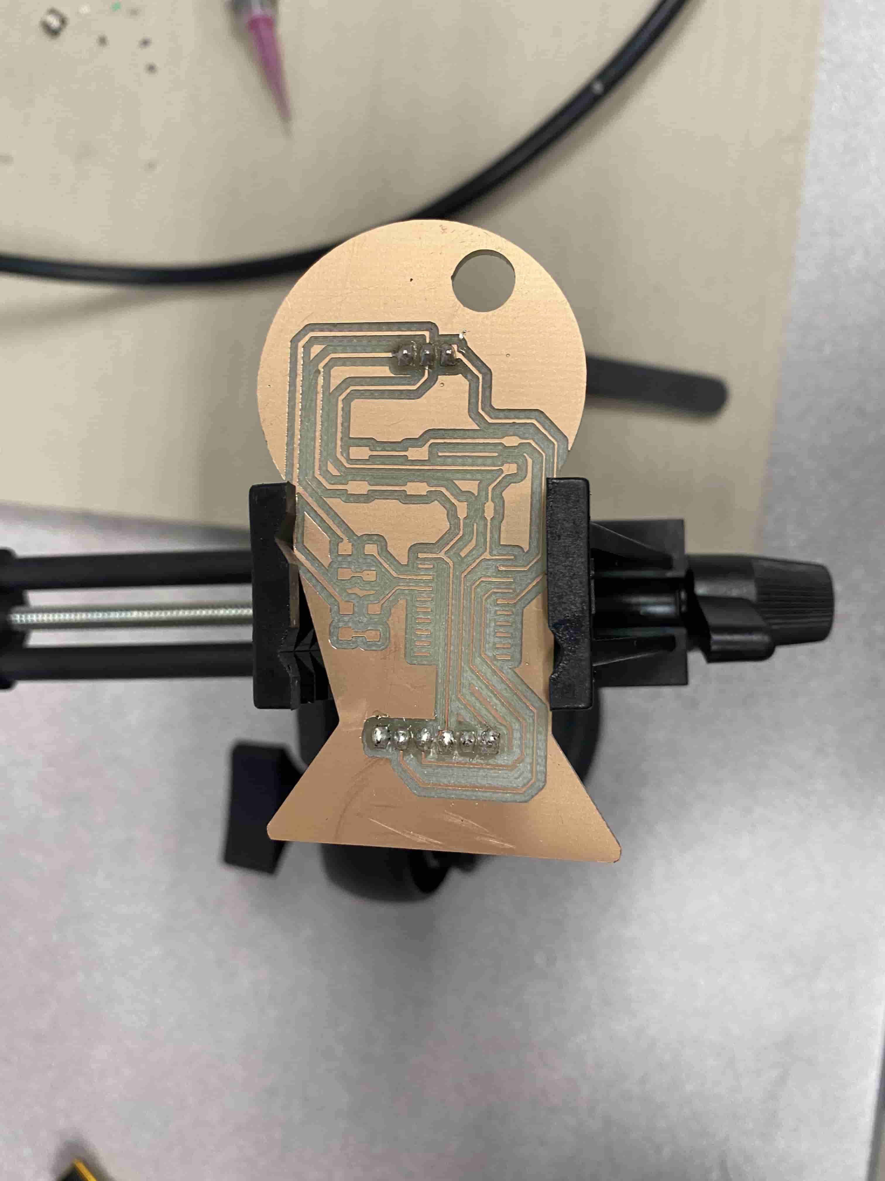
Once I milled out my board it looked like this:
Now it's the time for putting the cmponents on. from my experience from the week5's assignment, putting the big pieces last was the best option. However, I put the connector pins (headers) first because I used wire solder rather than solder paste for them. Reason to this is because using wire solder is stronger in this case and also it can withstand more heat. So that While I am putting all the SMD components I am not destroying the connecters.
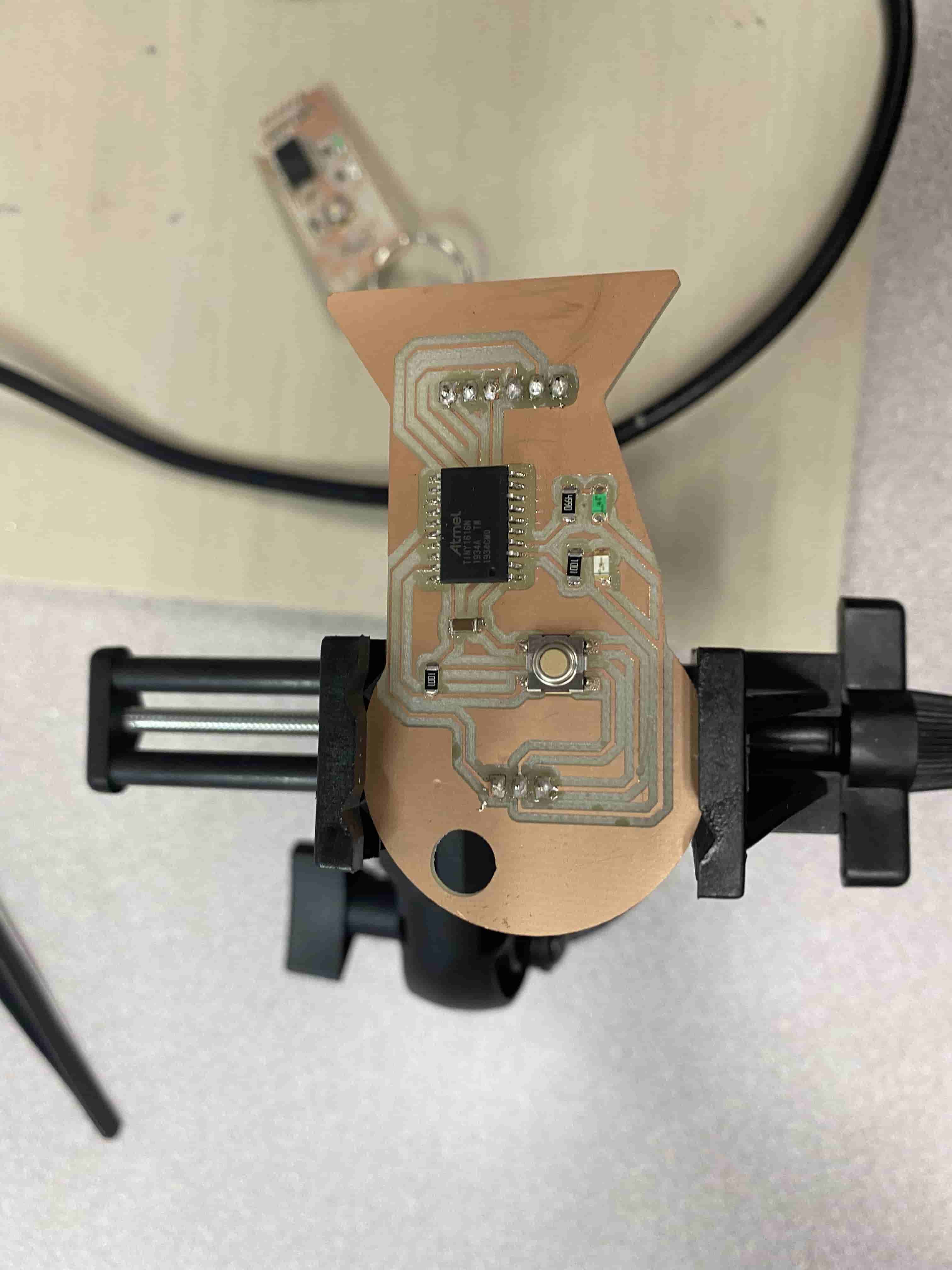
After placing the connectors and burning my fingers while trying to hold them there, I have started putting the SMD components. Finally my board looked like this:
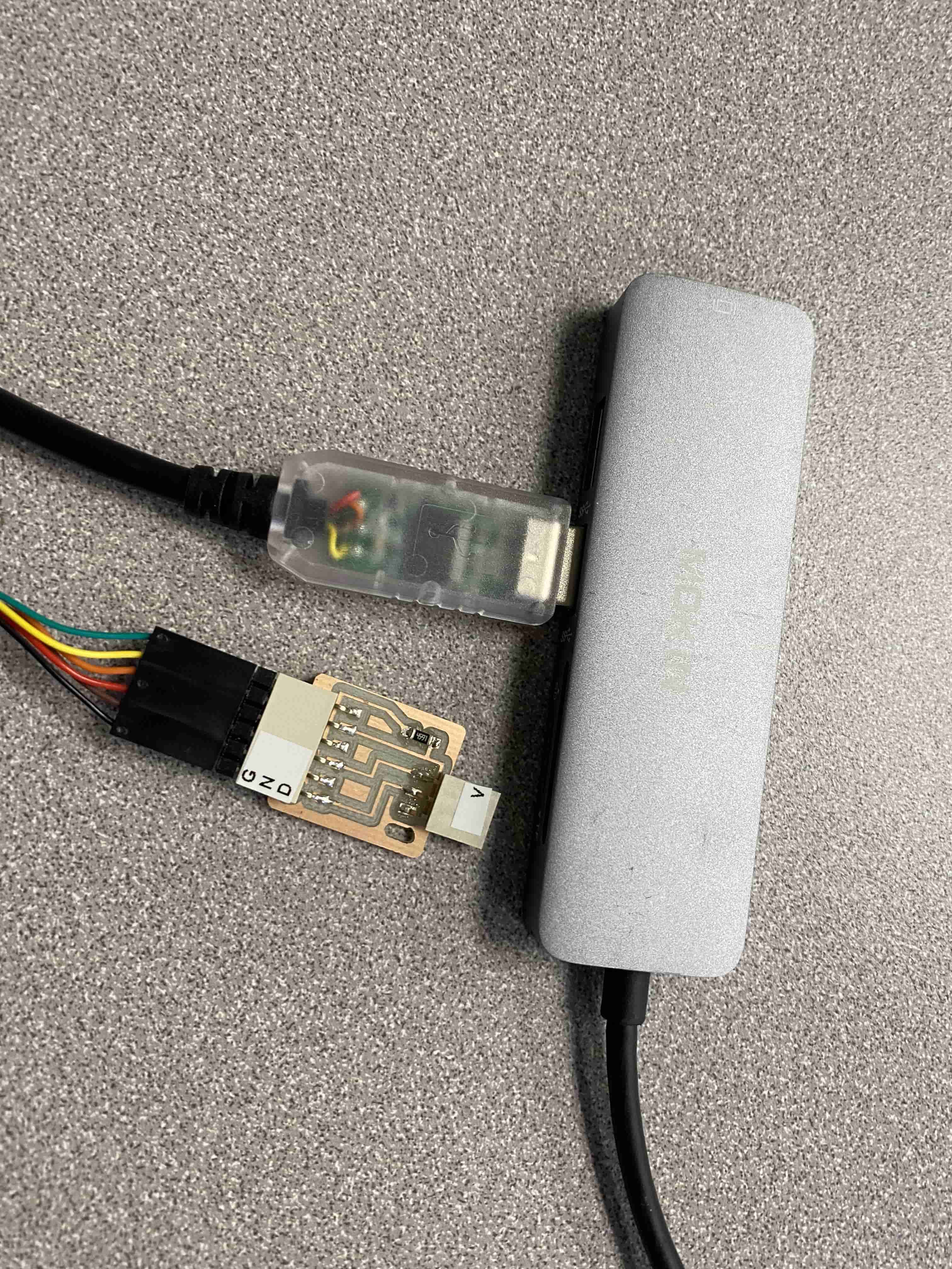
Now that I have completed my board, I have checked it with a multimeter and all the connections seemed correct. Hence I moved on to coding it. To code it I used a specific cable (FTDI USB-to-serial cable) that allows us to code it. We will later also use this cable (without the chip attached to it) to connect my board to the computer and make it talk to each other.
I used thee Fab Academy's echo hello-world code to code my PCB. Howver, because mine is a bit different, I have included some new stuff from me. For example it says "Hello my name is Tuna" in binary by turning on and off the LEDs.
Moreover, to code my PCB, I needed to set up my Arduino IDE to recognize my ATtiny 1616. For this I followed these steps:
- Open File / Preferences in Arduino IDE
- Add http://drazzy.com/package_drazzy.com_index.json to the list of “Additional Board Manager URLs”
- In the Tools / Board menu, choose “Boards Manager…”
- Find megaTinyCore and click “Install”.
- Close the Board Manager.
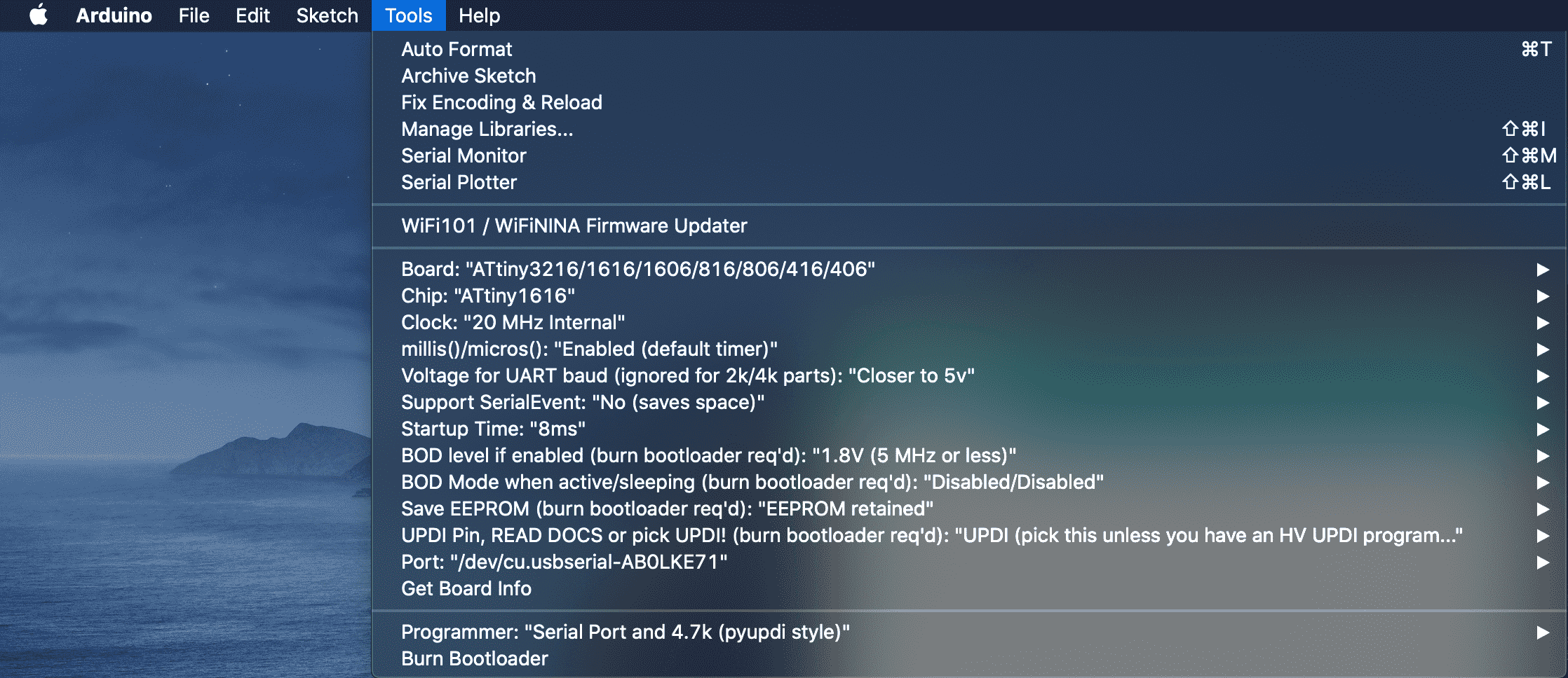
- In the Tools / Board menu, choose “megaTinyCore” and pick the particular microcontroller you’re using. In my case it's ATtiny 1616.
- In the Tools / Programmer menu, choose “Serial port and 4.7k (pyupdi style)”. This option only appears when you have chosen a megaTinyCore microcontroller.
After completing all these steps now my computer was able to recognize my ATtiny. Hence, I needed to upload the hello.t1616.eecho code to my board.
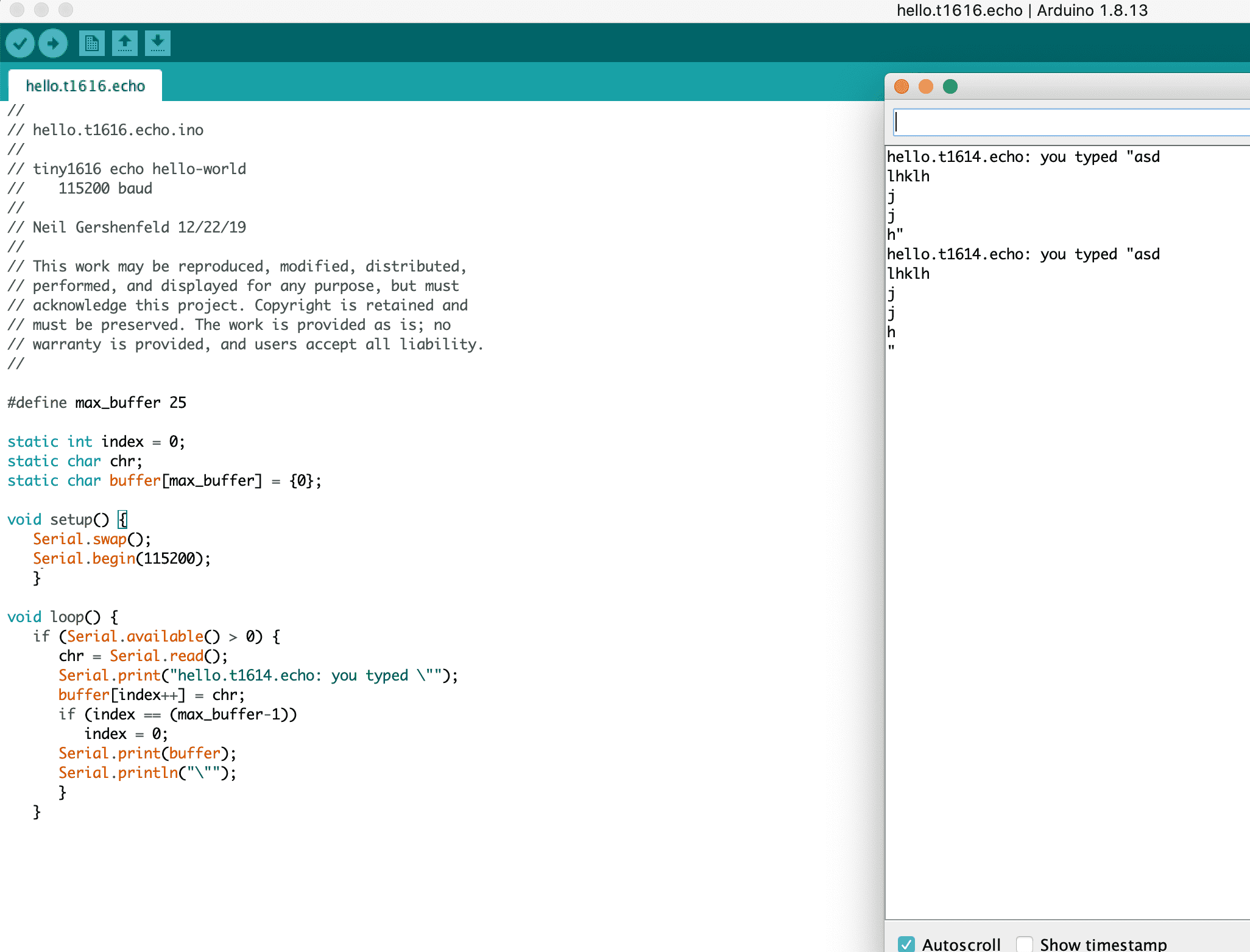
In this code we first define an variable called max_buffer that holds 25. Later we will be using this variable to create a char array with the size of max_buffer. In the void setup() function we see two lines of code the first one is my add-on. The reason I have added that line of code is becuase ATtiny1616 has 2 different Serial pins which means there is one ordinary one and one for back up. While designing my board, I have connected the TX, RX to those secondary serial pins which caused my board to not talk to the computer. Hence this line of code "Serial.swap()" changes and allows me to use those other pins. the second line of code starts the serial port at 115200 frequency.
Below, we have a void loop() function. this function loops continuously. Inside this loop there is a code that takes in a text from the user via the serial monitor at Arduino IDE. The code later than saves what the user typed and then prints out to the serial monitor.
After swaping the serial pins, I was able to upload the code and it worked really good.
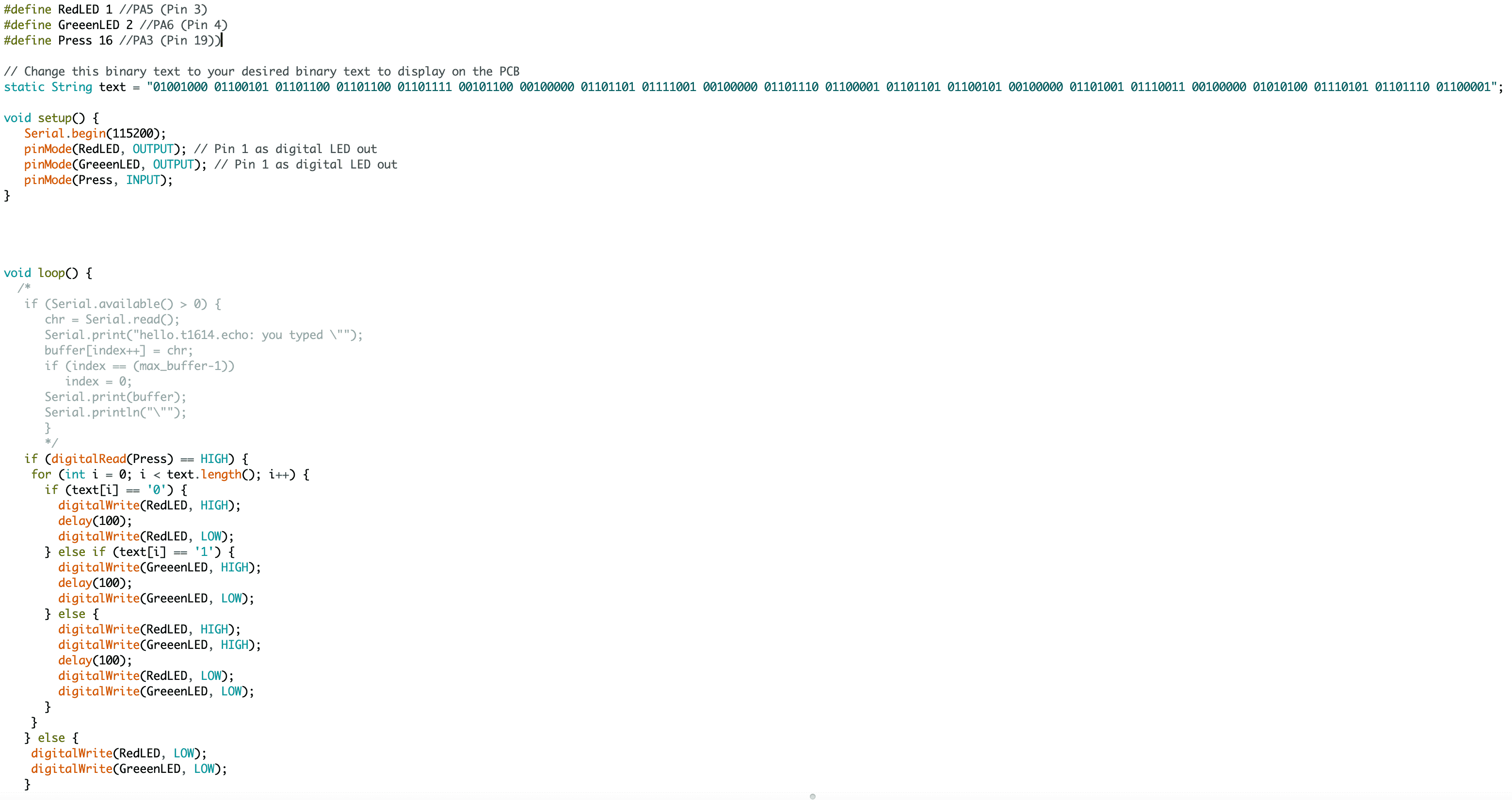
However, I wanted more from my board, I wanted so that when I press the button it will display a message in binary by using the 2 LEDs on it. I coded so that the code takes in a binary message and then checks for each 0 and 1 in the string and for each 0 it turns on the red LED for 0.1 seconds and for each 1 it turns on Green LED for 0.1 seconds.
After coding I have connecteed it to my computer and started running it and it was a success. It worked well!
Below you can see a GIF of it working: