Assignment:
Group Assignment:
1# Test the design rules for your printer(s)
Individual Assignment:
1# Design and 3D print an object (small, few cm) that could not be made subtractively.
2# 3D scan an object (and optionally print it)
Brainstorm
Softwares:
 - PrusaSlicer - A CAM software that allows you to do final editing to your object and add custom supports and 3D printing options and converts your .stl file to G-code
 - Fusion 360 - A CAD software that allows both 3D and 2D designing
 - MetaShape - A 3D scanner softwares that can convert your vides and photos in to 3D environments or objects
Machines:
 Original Prusa i3 MK3S 3D Printer - It is a great 3D printer that is really easy to use, set up and has good qualities.
Group Assignemnt
For our group assignment we wanted to test how acurate our 3D printer is so we did 2 different tests. The first test is used to calculate the error margin in 3D printers. This test is design by me and has one female part and another male part that can interlock. If the parts connect to each other flawlessly then there is no error margin, if not you measure it with vernier caliber and see the error. The second test is an "All-In-One 3D Printer Test" that tests almost everything from overhangs to stringing. This test is made by majda107 and can be found here.
Interlocking Test
Because I designed this test, I might sund biased but actually this is a test print I have designed after a year of working on printers, fixing them, repairing them, fixing other people's 3D prints midway through, etc. I have obtain a lot of knowledge on 3D printing or atleast on Prusa 3D printers. One of the biggest challenges for me with 3D printing is size accuracy. When ever I try to print stuff that has to be really accurate, the 3D printer just cannot print in the same size. The reason to this is extruding. The 3D printer nozzle goes over the exact dimentions however, when extruding the molten plastic travels a bit which in most case its by ± 0.5 to 0.05 mm. This can cause a big problem if you want accurate parts that has to fit together. Some softwares such as PrusaSlicer has settings to fight against these errors but sometimes instead of helping they cause even bigger problems. Every type of filament has it's own error limit: most of them are in ± 0.5 mm zone and some are in ± 0.5 mm zone. Hence the PrusaSlicer mostly set to ± 0.5 mm error margin but if you are using filament with a ± 0.05 mm error margin then you have to test print and adjust your PrusaSlicer settings accordingly.
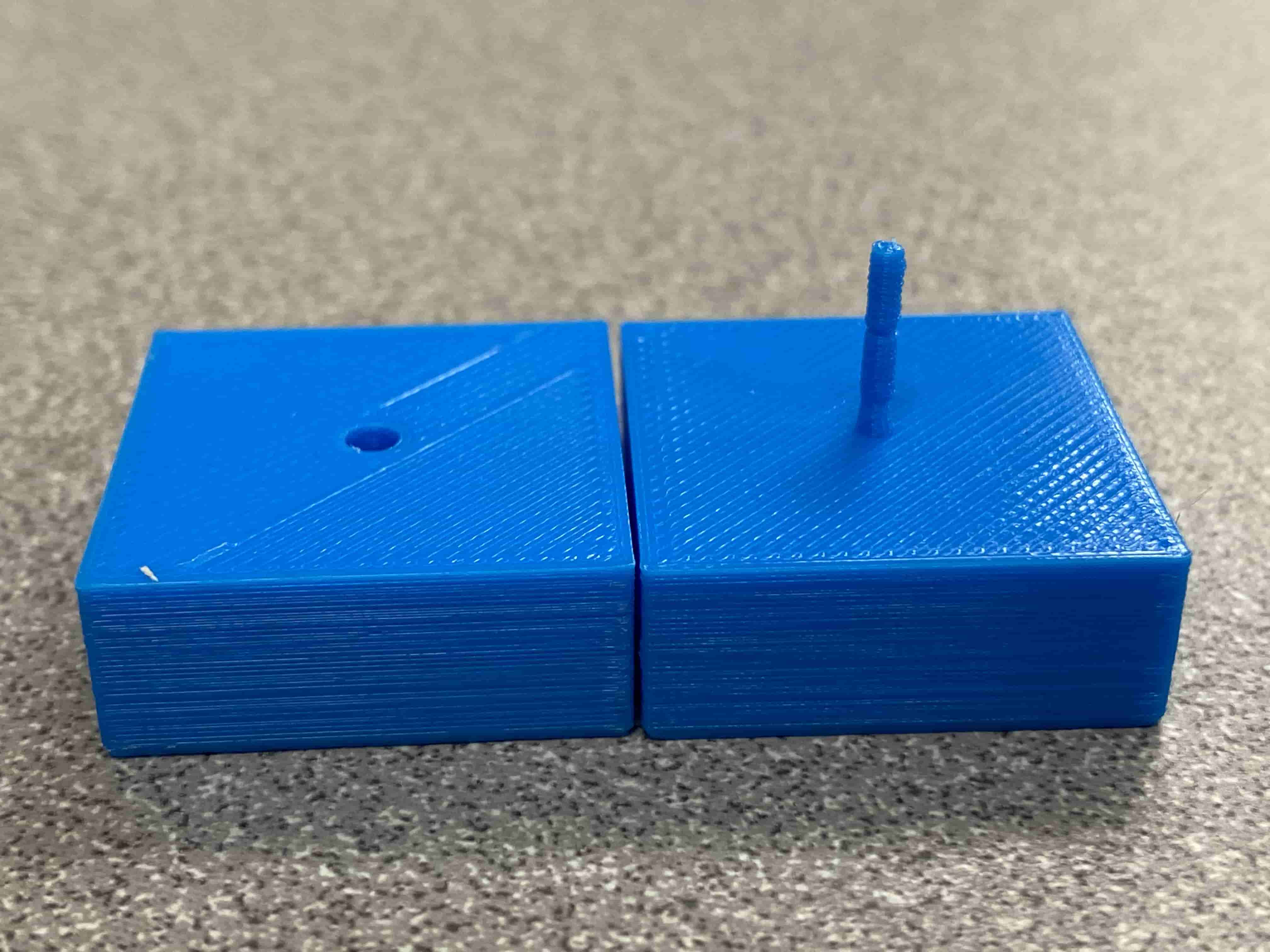
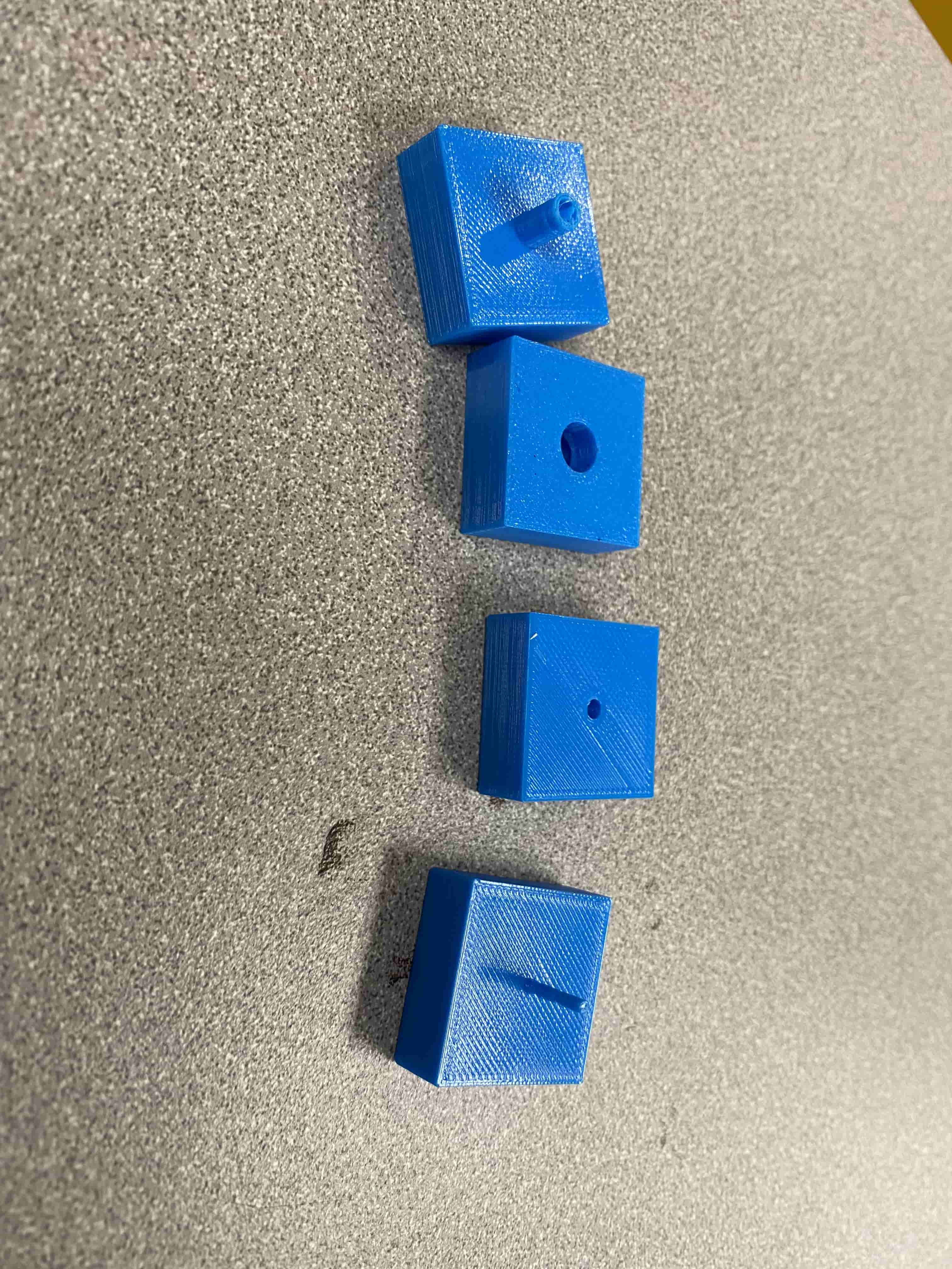
The design of the test is composed of two blocks that are 1'x1'x1cm. The reason there are different units is to test the accuracy of the printer in different units, then in the first block of the pair we have a hole with a locking mechanism inside it and in the second one we hace a stick coming out with a groove on it to lock with the locking mechanism.
I used Fusion 360 to design them. In Fusion 360, I have first created a square by 1 inch to 1 inch and then extruded that by 1 cm.
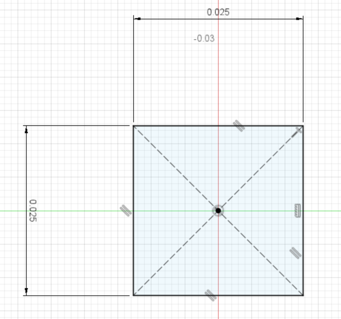
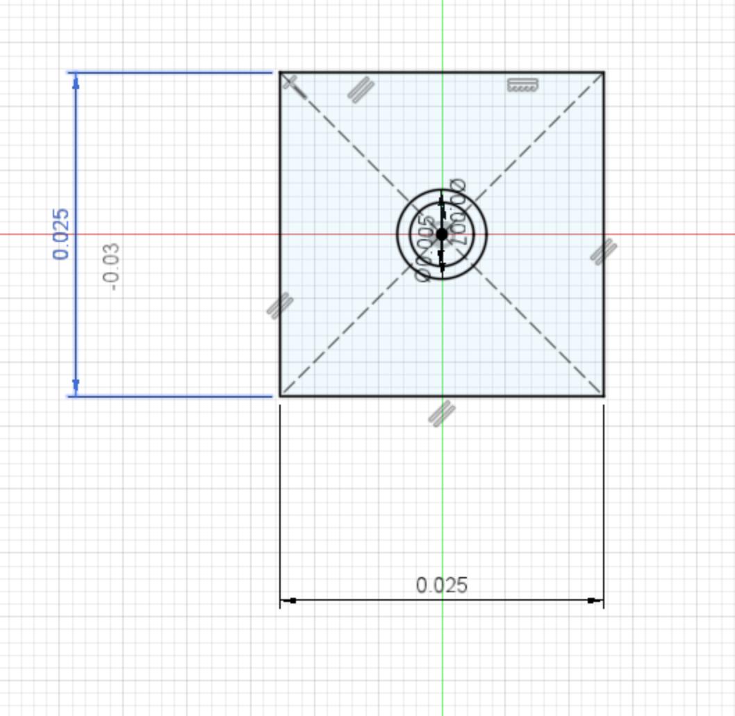
Then on the top of this block I have created another sketch that has a circle with 2 mm in diameter (which I ended up changing to 5 mm in the second test because it was too small) and extrude that to 1 cm too. For the second block I drew 2 circles with 2 mm diameter and 3 mm diameter and made a hole with the 3 mm diameter one and extruded and angled the area between the 3 mm one and 2 mm one to have the locking mechanism. Then on the 1 cm stick I have created a groove at the same place as the extrusion in the hole of the second block.
Measuring them to test the accuracy and the error margin of the print.
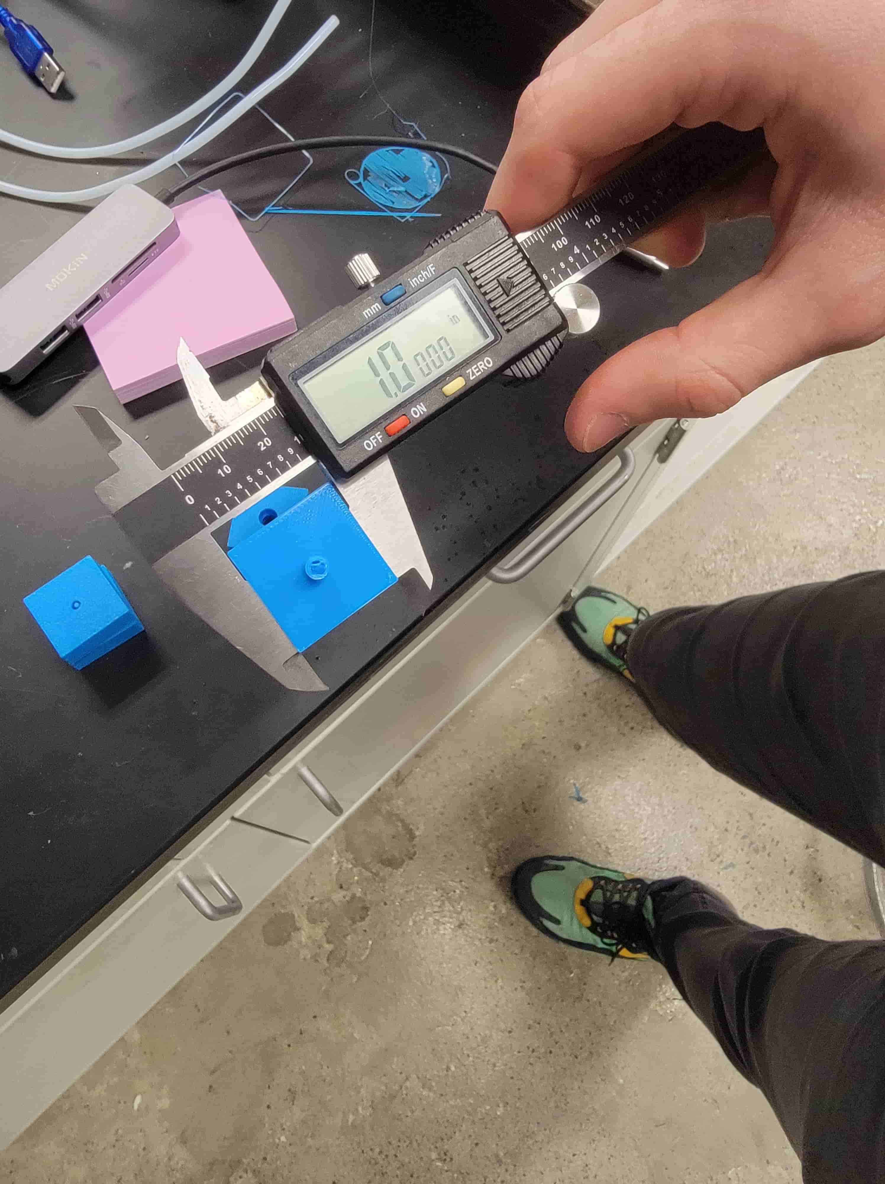
We repeated this step twice to find the perfect size. Initially we designed it so that the stick's size is 0.05 mm smaller than the hole's size and that gave a huge gap and in the second design we have made the stick and the hole have the same size but we still got a gap of 0.5 mm. This shows that the filament we are using has a 0.05 mm error margin and the PrusaSlicer is causing the problem.
After taking the data we saw that the difference between the measurements and the ideal print size is 0.05 mm. However, when we check the size of the hole it was 0.5 mm larger than what it should be. We think the reason to this is because the PrusaSlicer is trying to mitigate the error by leaving a 0.5 mm gap but in reality the error margin is only 0.05 mm.
All-In-One 3D Print Test
All-In-One 3D Print Test is great for testing almost everything. It comes with support test, stringing test, overhang test, bridging test, layer adhesion test, circle test and cylinder test. It almost checks every aspect of the 3D printing where errors can occur. Another great aspect of this test is that its all in one, in other words you don't have to print multiple stuff but you can just print this and make sure that it works.
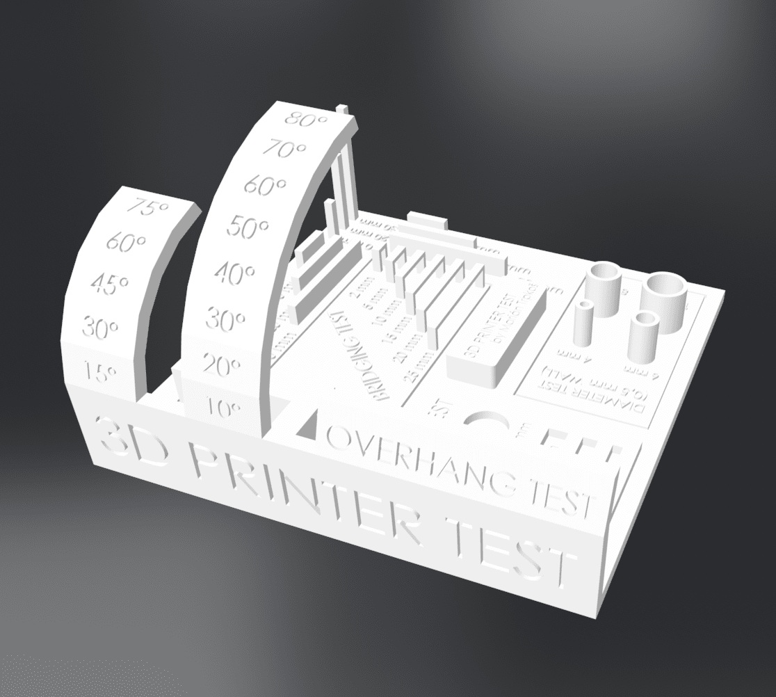
This test is created by Majda107 and can be found at thingiverse.com. There are mini vresion of this test too but we decided on using the original version of it.

Aftere it was finished we took measurements and saw the same error we got in my test for the hole on this test too. This proves our theory that the actual error margin is 0.05 mm and the PrusaSlicer is messing it up by trying to mitigate the error by 0.5 mm.
Individual Assignment
Magnet Embeded Frame:
Actually, at first I wanted to make a hollow sphere container with magnets embed in it. The sphere container will be made from 3 different parts: the top part, the bottom part and the hinge. However, because the printer I was printing on crashed my print was failed midway. Fortunately, I was able to print the most important part: the magnet embeding part. Moreover, when it was failed it looked like a picture frame so I decided to use it as a picture frame.
Each of the semi sphere suppose to have two magnets on the front and a hole on the back for the hinge to go into. The hinge would allow the semi spheres to turn and open and the magnets would act as a locking mechanism. I wanted to do this because in our Fablab, the SD cards for the 3D printers always dissapear, so I decided that if we have a cool container people will start using it.
The speciality of this design is that in substractive manufacturing you cannot embed stuff inside a material without cutting opening a hole, however, with 3D printing you can just print out out a container put something in it and then cover on top. This allows to manufacture hollow enclosed spaces that cannot be manufactured otherwise.
Initially I have set up some parameters for my design. I did this because if any error in my print happens I can go back to Fusion and quickly adjust my parameters and my design would change accordingly.
After seting up the parameters, I have created a big circle using the parameters and some inner circles representing the places the magnet and the hinge will go. Then I have created one pair of circles for the magnets at the top of the main circle and than a small 5mm diameter circle at the bottom for the hinge.
At first it started printing really well. I stand infront of th print until it printed enough so that the magnet holes would be as the sam height as the magnet. Than I have placed the magnets inside and waited until it covered them over.
It took arund 30 minutes to come to the height enough for me to put the magnet in. The reason why I did not put the magnet in earlier is because most of the 3D printer nozzles (including the one I am using) has only 0.8 mm tolerance. In other words they require the space next to the nozzle to be at the same height as the tip of the nozzle minus 0.1 mm or below. This is because 3D printing is actually not 3D printing but 2.5D printing. Currneent 3D printers do not use 3 axis at the same time. They always do layer by layer. Hence the Z axis is always used by itself.
Moreoveere, as you can see when the print finished I did not get a semi sphere rather than that I got a cool ring. This is because the oprinter I was using crashed while I was printing and I had to fix it but it was too late because I already used my magnets. Hence Instead of making a container I decided that I will use my print as a frame that can stick to metal.
In this gif above we can see that the magnets inside the frame are strong enough to hold the frame upright in a windy day. Hence it proves the concept that it could have made a proper container and will make a good frame.
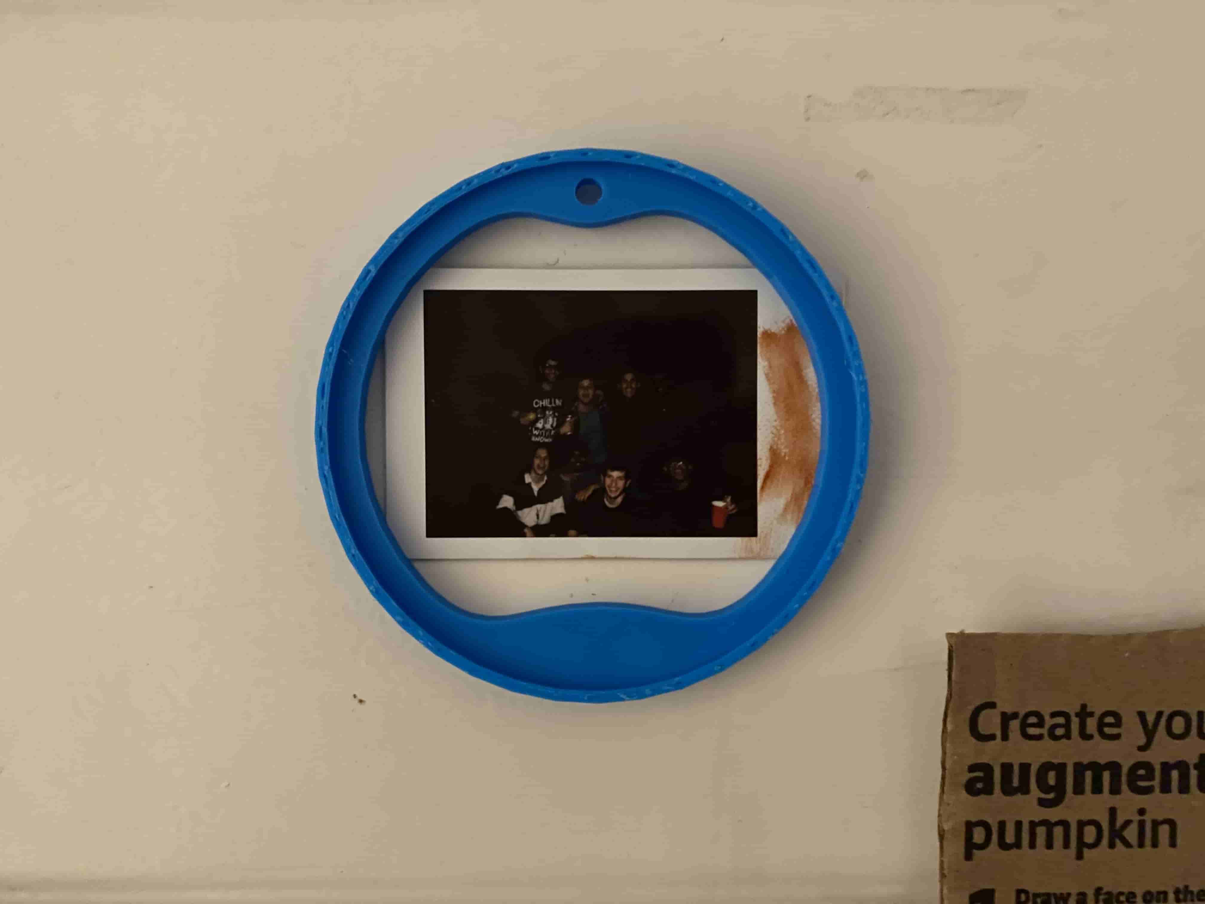
Because my dorm room's door has a metal cover on it, Magnets can stick on it. Hence, using my frame I now can pout photos on my dorm door showing my roommate and me.
3D scanning:
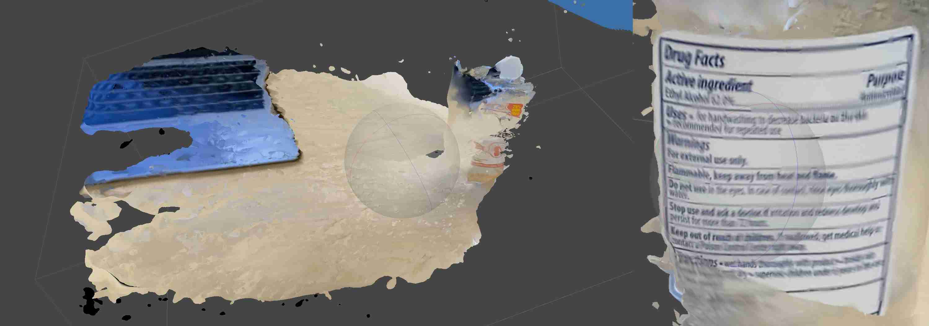
For my 3D scanning assignment I wanted to scan a hand sanitizer because currently we are in a pandemic and also hand sanitizer has text on it and I wanted to see how accurate I can 3D scan it.
Unfortunately, I was not able to use an actual laser 3D scanner which takes photos of the object and then using laser it detects the depth of the object. This allows incredibly accurate mesh verticies. Instead of this I used a software called MetaShape. Metashape is a great software because even with using videos it can create really accurate 3D scans and also it is incredibly easy. Even though I had no prior knowledge I was able to create a 3D scan with almost no effort. The only downside is because there is not a machine taking photos rather than that a user takes a video and uploads this creates the problem of innacuracy and Metashape uses SO MUCH time to fix and align all those frames in the video.
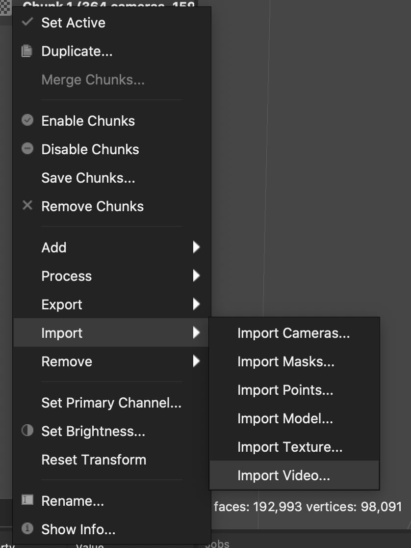
The first step of creeating your 3D scan is obviously taking a video. Then you open Metashape and right click on the "Chunk 1." This will grant you with many options, Metashape cannot directly convert video into mesh verticies hence, we need to convert the video to frames, or in other words images. Fortunately Metashape has a function to do that. after you right click you go to "import" and then click "import video..." and select the video you want to import. Make sure that you select an empty folder because in my case for a video that was 10 seconds long I got around 400 frames and I stopped it mid way because it was taking too long.
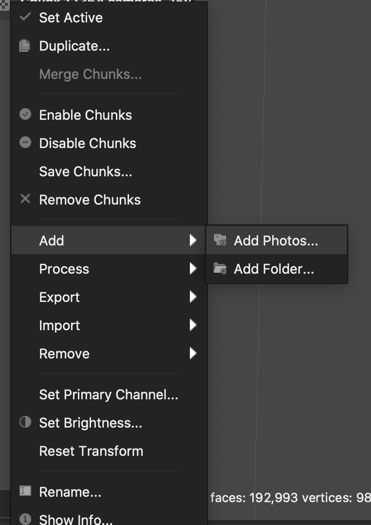
After Metashape converts your video to A LOT of frames, you again right click to "Chunk 1" and then select "add" -> "add photos." Then select all the photos Metashape just created. Make sure that all of the photos are complete in my case photo number 399, 398, 397 and 396 were corrupt and only half of them were visible which caused a problem. If in case this happens just delete those corrupt ones and retry addign the photos.
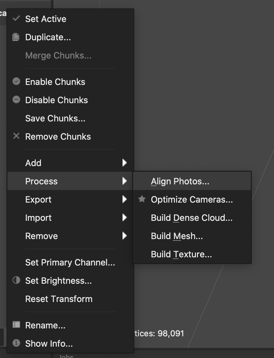
After you add your photos, under "Chunk 1" there should be a new folder and on the folder it should say "(0/x) aligned" where x is the amount of frames you have uploaded. Before we start creating a mesh we need to align these photos. To align them, right click at "Chunk 1" and click "Process." This will give you many options, we want to do all of them one by one starting from the very top one "Align photos." All these processes aligns photos to createe verticies then creates verticies then creates a mesh then creates a texture on to it and Voila you have your 3D scan.
At the end my 3D scan looked like this: