Assignment:
Group Assignment:
1# Characterize the specifications of your PCB production process
Individual Assignment:
1# Make an in-circuit programmer by milling the PCB, optionally trying other processes
Brainstorm
Softwares:
 - Vpanel - A CAM software that talks with Roland SRM-20 Desktop mill to send the job
 - MIT Mods - a great software that allows CAM software for multiple devices at the same time
Machines:
 Ronald SRM-20 Desktop Mill
Group Assignemnt
To characterize our PCB production process, using Roland SRM-20 Desktop Mill, we did multiple tests on Roland SRM-20. Even though our Desktop Mill is almost brand new doing these tests allows us to have better insight on how precise and efficient the Desktop mill is. As a group we downloaded a test file for our machine. This test file consisted of different slit cuts that shows how precise the machine can cut.
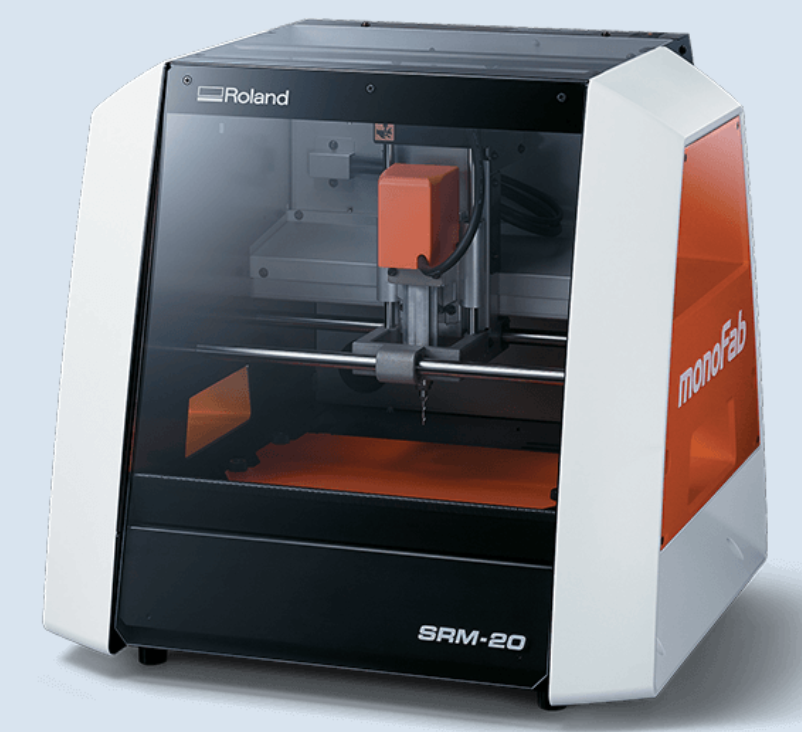
The Machine: Roland SRM-20 Precision (Desktop) Mill
For our PCB production process we have used Roland SRM-20 to mill out a single sided copper PC Board (PCB). Roland Can take many different bits ranging from V shaped ones to ball nose ones. For this assignment our group used one 1/32" flat end mill to cut the outline and one 1/32" ball nose end mill to do the tracing. The specifications of Roland SRM-20 is down below:
- Workspace Area: 203 x 152 x 60 mm (x, y, z)
Workspace area is the area in the machine where you can do your job. Even if you could put a material larger than workspace area, the machine would not be able to reach all the way. - Max workpiece weight: 2 kg
Max workpiece weight is the maximum allowed weight for the material to cut. If it's heavier than 2 kg it is probably bigger than the Workspace Area, but let's say you found a material dense enough to fit the workspace and go over the 2kg limit, in that case the Roland SRM-20 Mill would not be able to mill that material because of it's density. Hence the Workspace area and Workspace weight are related. - Operating speeds: 0.1 mm/sec ~ 30 mm/sec
Operating speed of Roland SRM-20 Precision Mill is the speed in which the machine operates and do the job such as milling, cutting, tracing, outlining, hovering, traveling, etc. This is important because if you have a really tough object such as PCB the mill should go slower to not break anything but if you have a softer material such as wood there is no reason to go slow. In that case you would want to go fast. - Spindle speeds: 3000 ~ 7000 rpm
Spindle speed is the speed in which the bit for the Roland SRM-20 Precision mill rotates around its central axis. At first glance it might seem unimportant however, it is the most important of them all. This is because the spindle speed grants which material it can mill. if it has a really high speed range then it cannot mill metal or PCB however, because Roland SRM-20 has a fairly low rotation per minute (rpm) rotational speed it can mill through thin layers of metal. In our case that is a PCB. - Input Formats: RML-1 or NC Code or RML-1/NC Code
Input formats is the input file the Precision mill takes and reads to understand where to go and what to do. Unlike most of the machines, Roland takes 2 different types of input file: RML-1 and NC Code. NC code is more commonly used in the industry, however RML-1 is more focused on Roland hence can offer better usage on Roland. The difference between RML-1 and NC Code is that RML-1 is specific to Roland while NC Code is more universal. - Allowed Material: Chemical Wood, Foam, Modeling Wax, Acrylic and PCB
Allowed Materials are the materials that Roland SRM-20 Precision Mill can defineetly mill. These materials are safe to use in the Roland Mill and if in good use, they will not pose any problem and danger. It is not uncommon to use Roland for other materials such as steel sheets however in those cases roland cannot operate as a mill but operates as a engraver.
For more information we, as a group collected many information from many websites and sources and rewrote them in a document linked in here
Testing File:
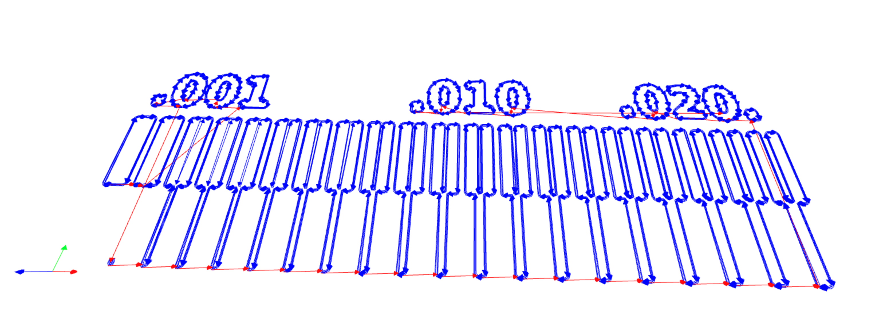
For the testing file we went to the Fab Academy Tutorial Page to get the Test File. The test file is as seen below:

After downloading the PNG file we head on to the Fab Modules to input our PNG file and get an RML file. Initially Fab Modules website is a plain website with almost nothing however, after right clicking we get tons of options.
- First right click, then click at "programs", then "open server program", then "Roland" -> "SRM-20" -> "PCB png"
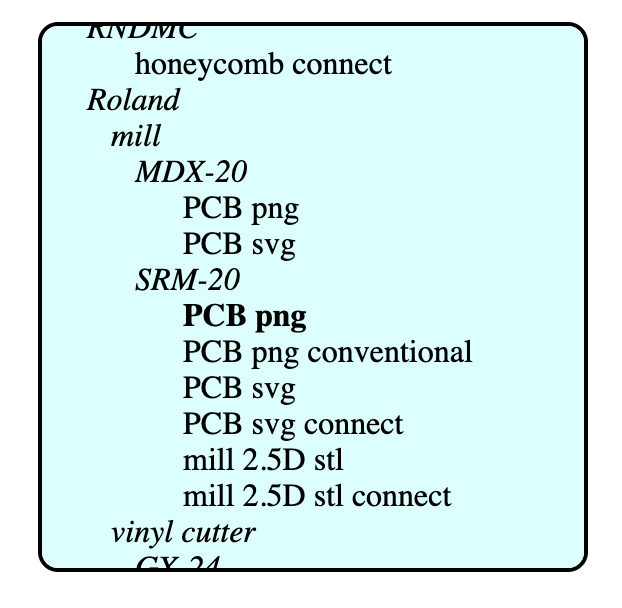
After following the first step you should get a page full of modules that converts PNG in to a vecotr image and then converts that into a file that can be understood by the Roland SRM-20 Precision Mill.
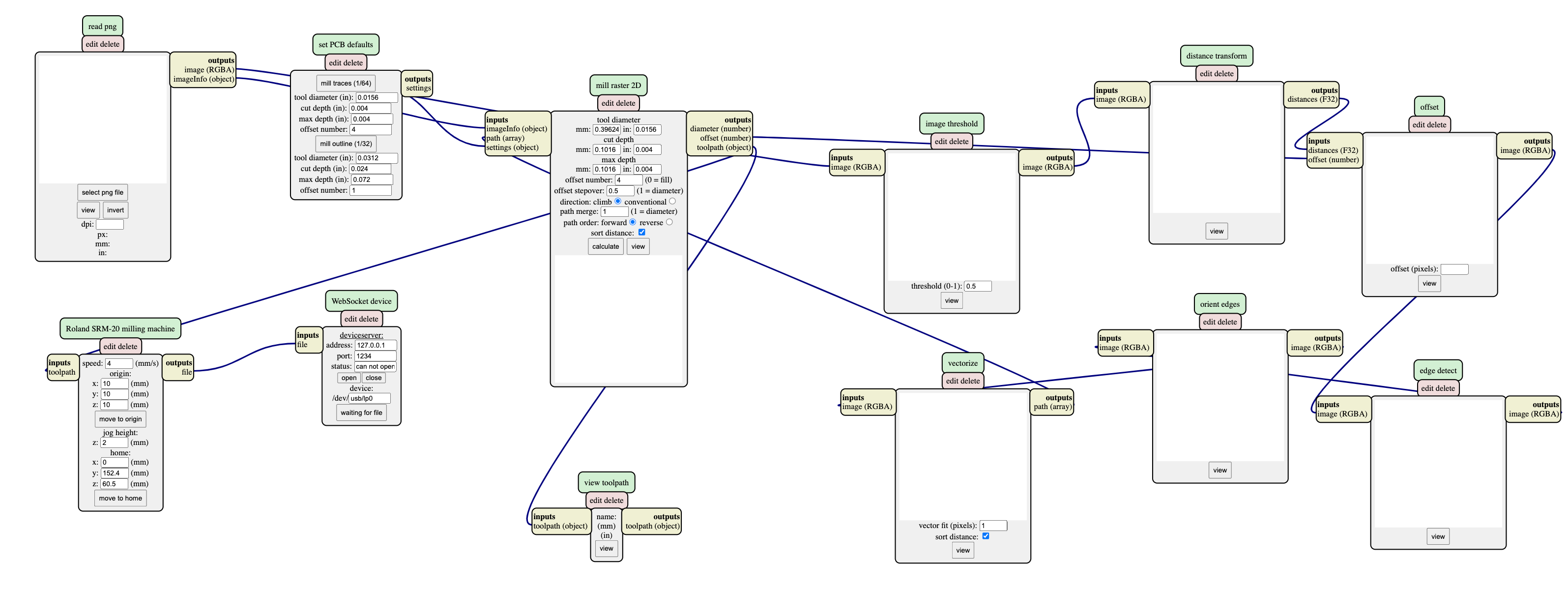
However, as you can see for the final step we have a module called WebSocket Device. This modules helps Fab Modules (or in short "Mods") to connect to the Roland. However, because while as a group we were using our computer to create this file we want it so that we can download the RML file rather than sending it directly to the Roland.
For this you right click -> "Modules" -> "Server Modules" -> "file" -> "save"
After doing these steps you should get a new modules called "save file." However, as you would see that module is disconnected for this we first need to disconnect the WebSocket Device Module. Click at the "inputs file" on the WebSocket Device Module and then click at the "Outputs file" on Roland SRM-20 milling machine module. Now do the same thing with save file module to connect them.
Eventually, your Mods page should look like this:
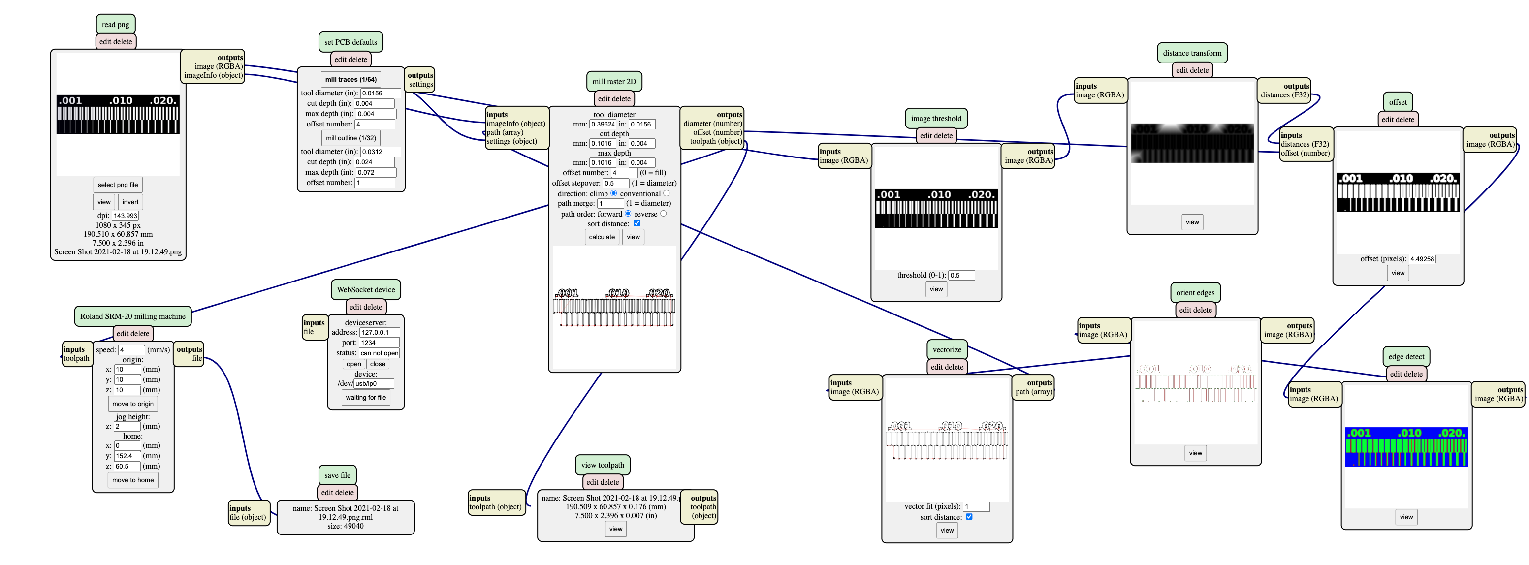
However, before we start the image tracing, don't forget to set both thee origin and the home xyz to 0. Now that we have the Mods set up we need to upload our PNG image. Click at the "Select PNG File" in the first module and then select your end mill size on the second module. For tracing we chose 1/64" end mill and for cutting 1/32" end mill. After selecting the correct bit we just click "Calculate" on the 3rd module and Voila your file downloads automatically. When it finishes downloading it will open a new page where you can observe the path tracing and see if anything is wrong. This is the path tracing for my group and everything looked fine:
Milling the Test File:
Now that we prepared the file, using a USB stick we transfered the file from our computers to the computer connected to the Roland. Before setting up the home, we put our desired end mill bit. After placing the bit, using the Vpanel for Roland SRM-20 Software we have adjusted our home position.
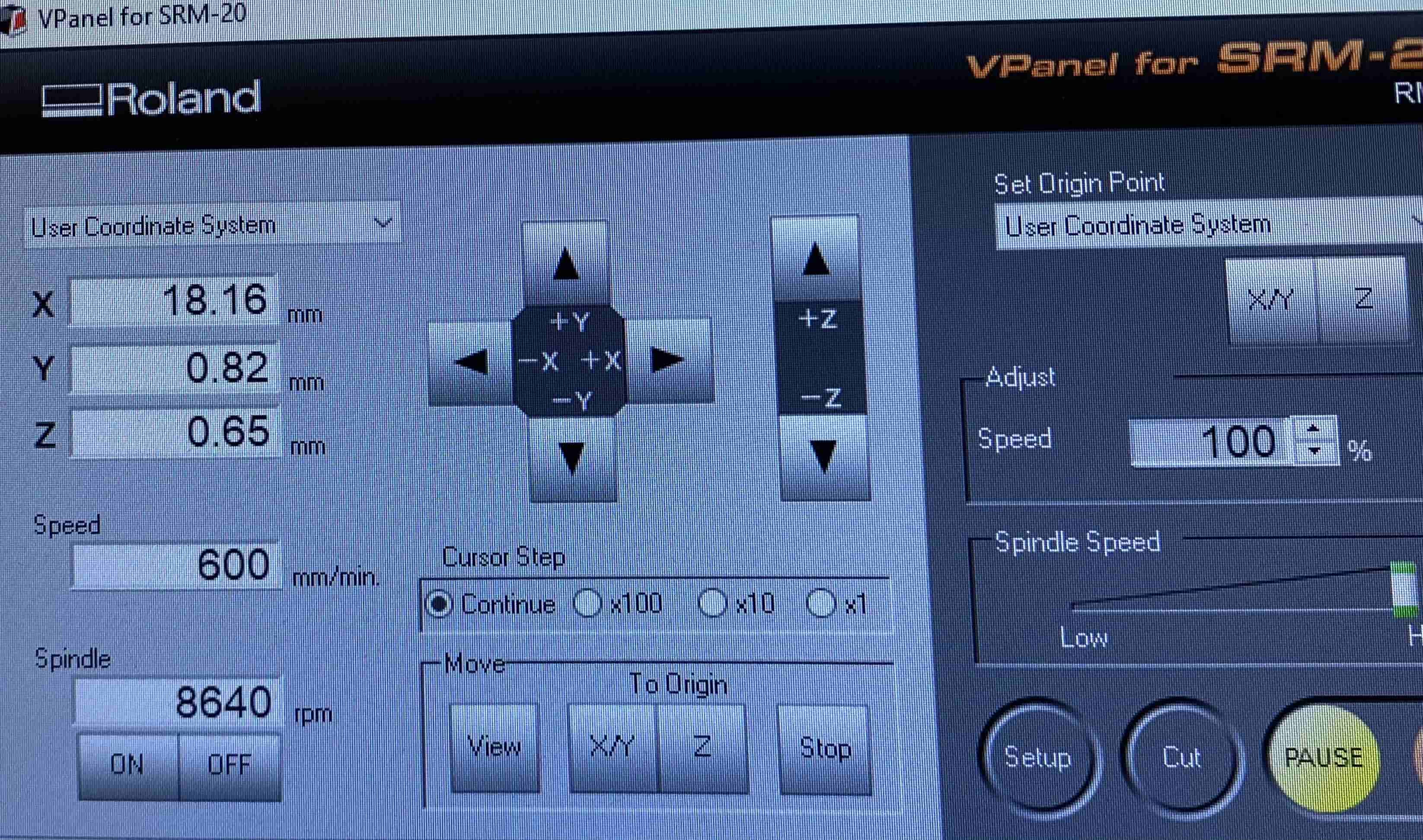
Using the Arrow buttons we first move our bit around the workpiece and then when we are in the desired location we click the "X/Y" button under the Set Origin part. However, for setting the Z axis we move to the middle of the theorotical place of our PCB and then lower the Z until you are around 2 mm above the PCB. Once you are there you losen the bit and it drops on the surface. This method makes sure that the bit is perfectly aligned with the PCB. Once you dropped the bit you click at "Z" under the set origin part in Vpanel and then you go up and click at "X/Y" in Vpanel under "Move/To Origin" part. Once you ready, you click at Cut and make sure to delete all the other previous files and then add your tracing file first and click output. This will start the Roland and Roland will automatically go to the origin and start milling.
Results of the Test:
After finish milling the test piece we used a Vacuum Cleaner to suck all the dust away and end up with the finished piece:
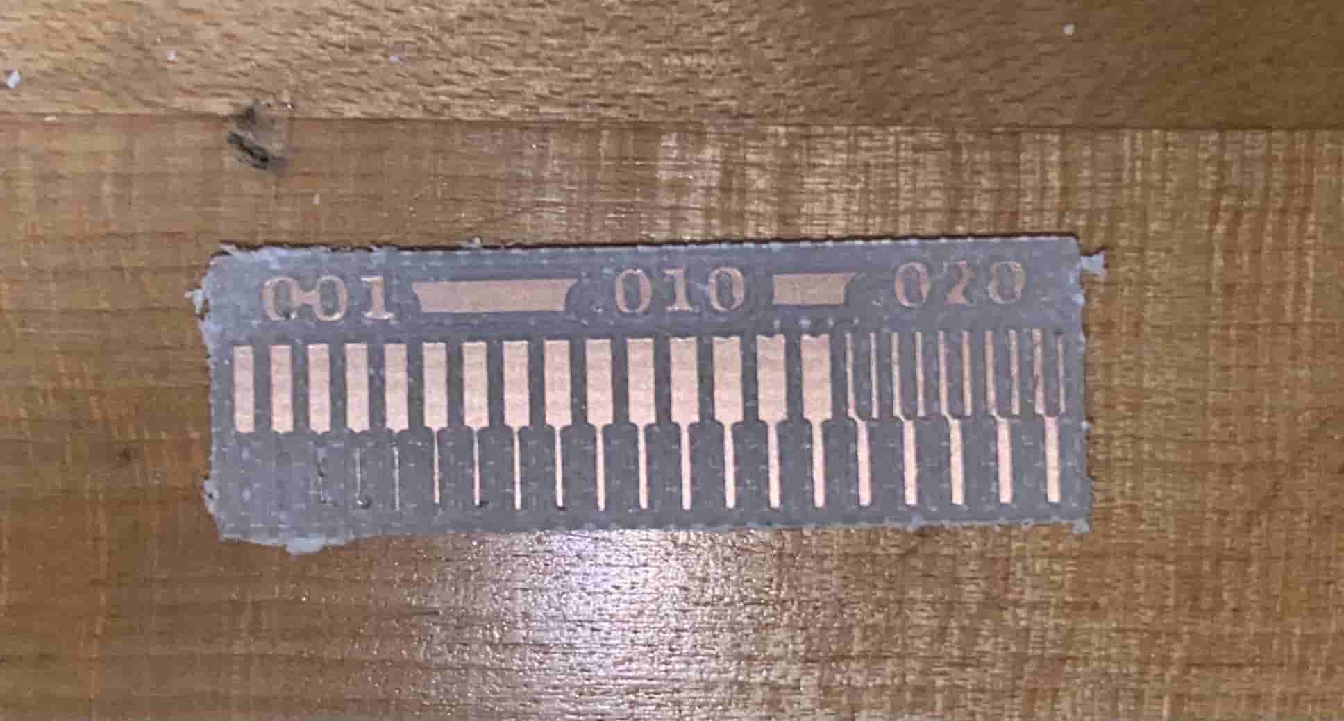
Compared to the first PNG image taken from the Fab Academy tutorial page, our final test results has a lot of differences. In first glance, it seems like the Rolan was not precise enough and cut over the tiny slits on the PNG image, however, if you look at the path trace, you can see that Mods did not even tell Roland to cut through there. Moreover, we can see that the numbers above should have been .001, .010 and .020. However, at the end we got 001, 010, 020 this shows that either Roland is not precise enough or because we used a ball nose end mill instead of a V shaped one, Rooland was not able to have precise cuts.
Individual Assignment
FabTinyISP:
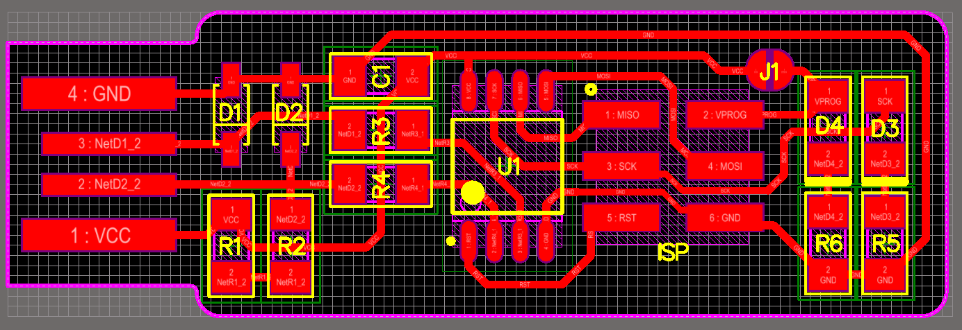
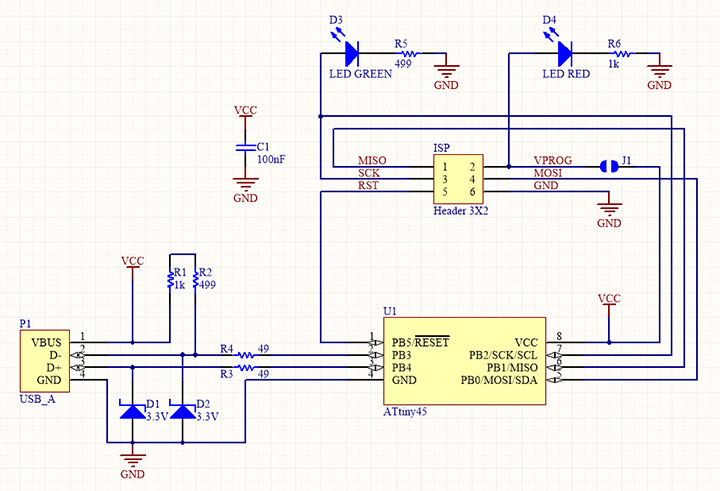
For my personal assignment I built a FabTinyISP. In the most basic understanding, FabTinyISP is a computer that programs other computers. It composes of resistors, diodes, LED, header pins and an ATtiny 45. the first two resistors makes sure that the computer recognizes the FabTinyISP as a valid device, the LED is used as a user interface, header pins are used for information transfer and the ATtiny 45 is used as the brain of the FabTinyISP.
Before putting the electronics on, I need to first cut out the FabTinyISP from the PCB using Roland. On the Roland, I have used a 1/32" flat endmill for the outline and 1/32" ball nose endmill to mimic the 1/64" flat endmill for the traces. The only downside of using this is that ball nose leaves deeper traces which can make your SMD parts get stuck on while soldering. For the stock material we have used FR4 variant of the PCB. The reason behind this is because one of the people in our lab tried to use FR2 and the FR2 started peeling when he tried to do through holes on the PCB. For this I used the Fab Academy Tutorial page for FabTinyISP and downloaded the PNG images for tracing and the outline cutout.
In the same way we did in the testing, I have uploaded the files to Mods and downloaded the RML-1 file. Then, I uploaded my files to Vpanel software and cutout the FabTinyISP.
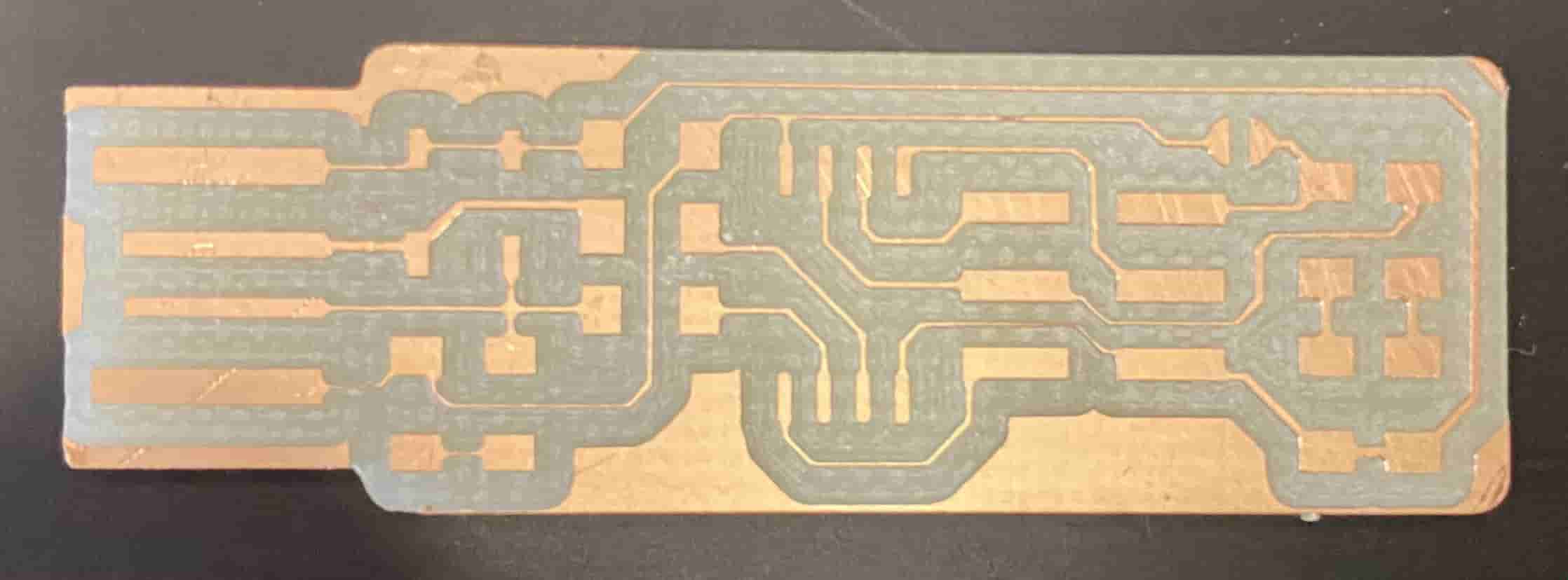
When it was finished I got this:
Unfortunately, I had to make 2 of these because for the first time, I placed all the components and when the time came to do the soldering for the USB part I have messed up my whole ISP so bad that the copper on the PCB scrapped off. Hence, I went to cut another one. However, when I tried to cut a second one, even though I set the Z axis, it was undercutting for the sum parts of the ISP and if I press the PCB with my finger and then zero the Z axis this time it was too deep. so much so that aftere finishing my board, while returning to the home position it barge through my ISP's usb part and destroyed it. Hence, the way I solved this problem is by first setting the X/Y axis and then going in the middle of the Therotical area where the ISP will be cut out and at there do the Z axis set. Another prevention for the destroying the usb part while homing is to increase the step height to 10 mm.
Another misfortune I have encountered was that, the resistors were mixed and instead of 499 ohms resistor I have used 499 kOhms resistor which made it impossible for the computer to deteect my FabTinyISP.
In my second attemp, I initially started with scrapping off the unnecessary copper part in front of the USB part of my ISP, and then I started doing the soldering for the USB part before doing the components. Because from my experience with my first attemp, while trying to fix the USB part I knocked ever all my parts. After finishing the USB part I have put all the pieeces togerher, and for J1 area I have connected the two parts via solder bridge.
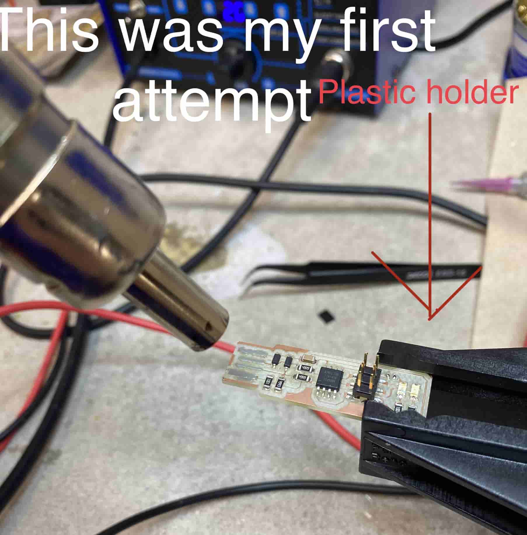
While I was soldering I have used a plastic holder to hold my FabTinyISP in mid air so I can use my two hands for other stuff. However, this came with the problem of trying not to melt the holder. Hence, I was only able to solder the one half of it and then turn it around 180 degrees and solder the rest. For soldering I have used soldering paste which is composed of flux and little metal beads which are 10-15 micrometer in dimater. The flux in the solder paste helps unoxidize the copper on the PCB so that the melted solder can stick and create a bond with the copper. While solder is binding with copper it creates a layer of alloy which is really strongly held together hence, once you solder the parts to the PCB even though you used just a bit solder, it is still really strong.
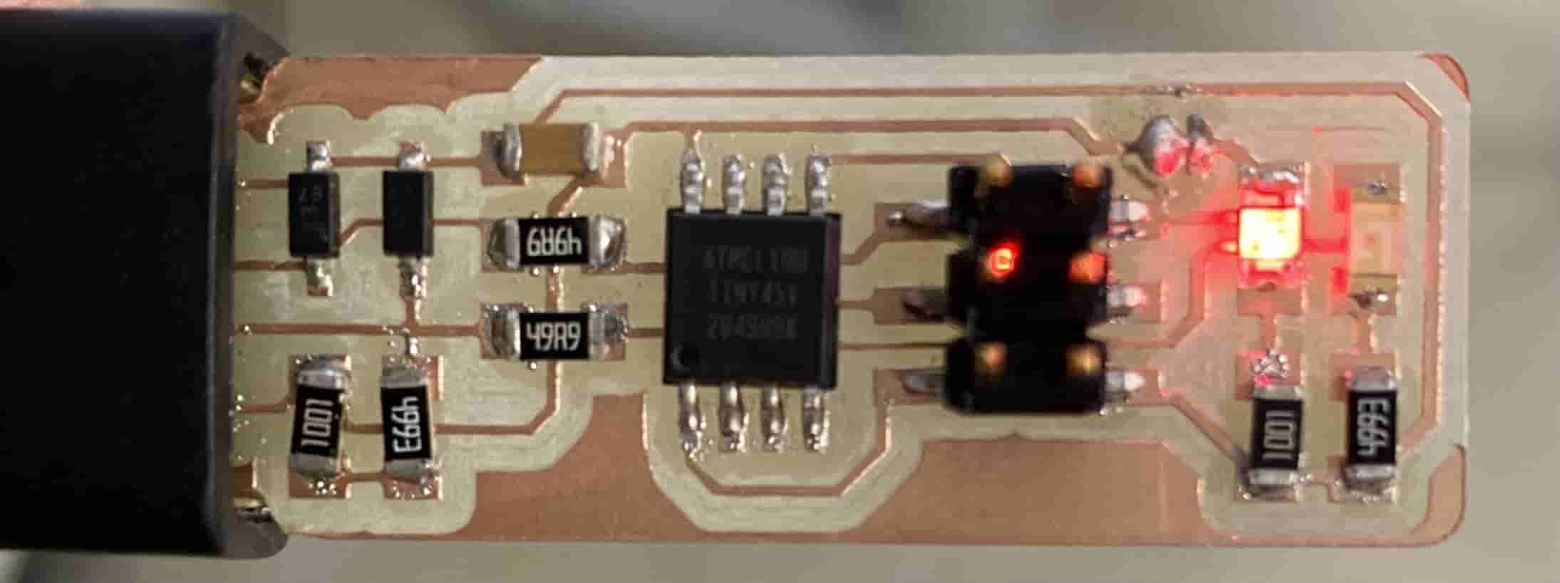
At the end I plugged it in a USB charger and this is how it looked:
I have completed the soldering according to this template given by Fab Academy Tutorial page:
After completing the soldering process, I have to program my FabTinyISP. For this, in my lab there were 2 options: either use a programmer (another FabTinyISP that already has been programmed and reset duse blown) or ATAVRISP (an in-circuit/in-system programmer).
However, before we start programming we need to download the proper softwares and firmwares. For this again using the Fab Academy tutorial page I have downloaded the software for Linux by typing "sudo apt install avrdude gcc-avr avr-libc make" in the command line and downloaded the firmware source code.
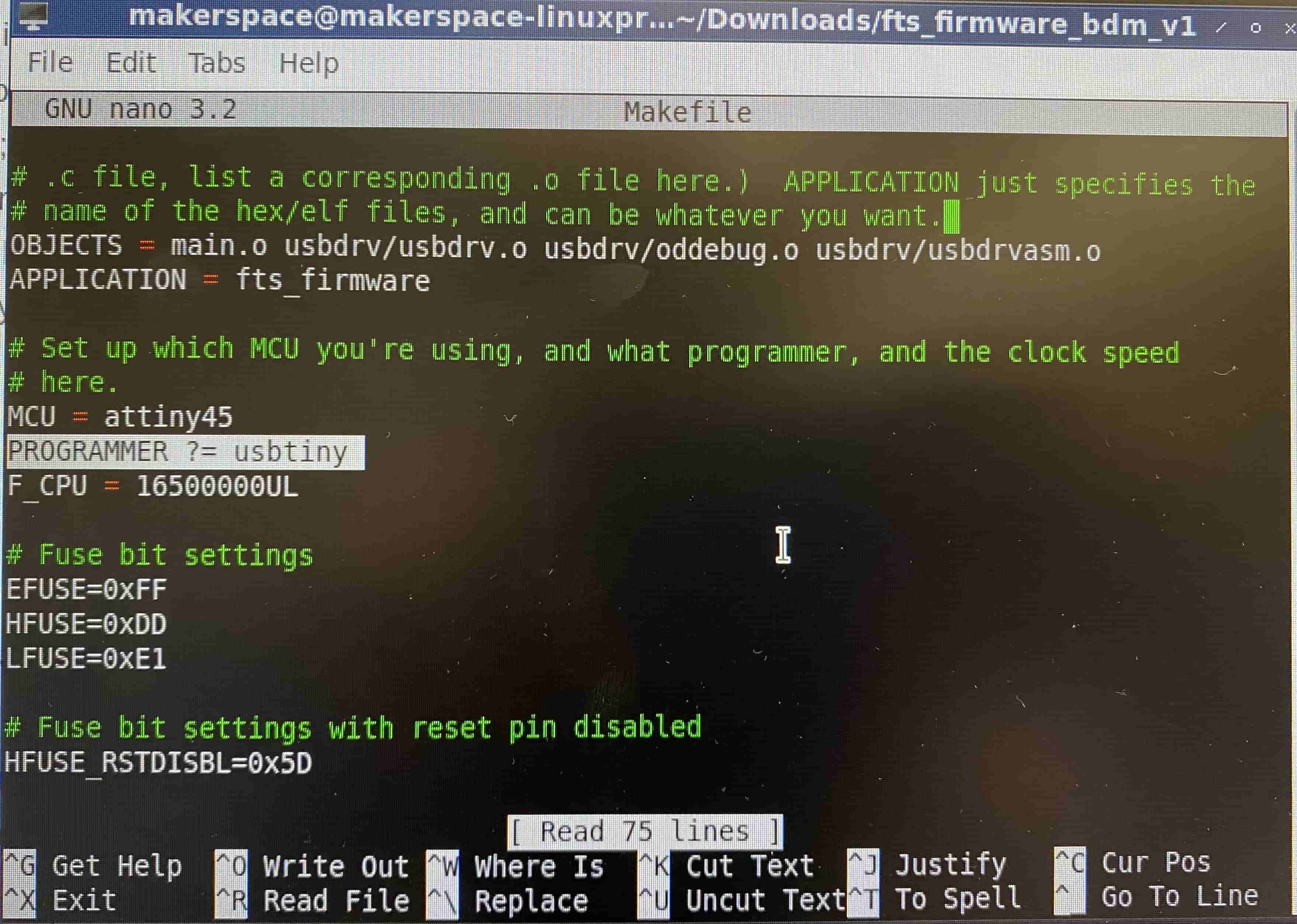
Now that I have the proper files, I need to edit them so I can have a personized FabTinyISP. This is important because it defines what kind of programmer we will use to program my FabTinyISP. Because I wanted to use someone else's FabTinyISP I have changed the the line on the Makefile to "PROGRAMMER ?= usbtiny"
This tells the computer that we want to use another FabTinyISP to program my FabTinyISP. To access the Makefile, I have first redirected the terminal to the folder the Makefile file is in and then typed nano Makefile to edit it.
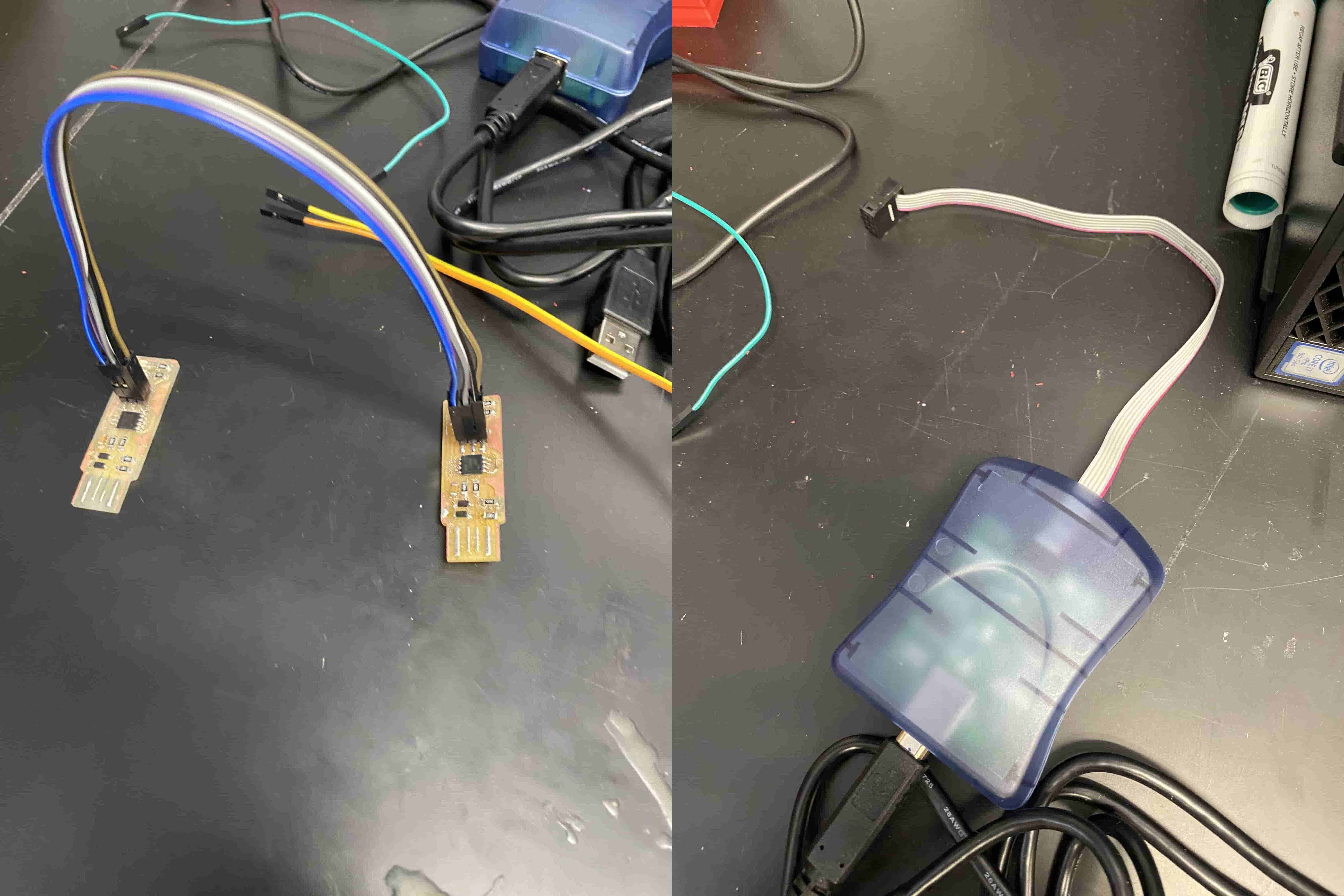
After editing the Makefile, I used multiple dupont wires to connect the other FabTinyISP to my FabTinyISP via the header pins and then plug them both in the computer.
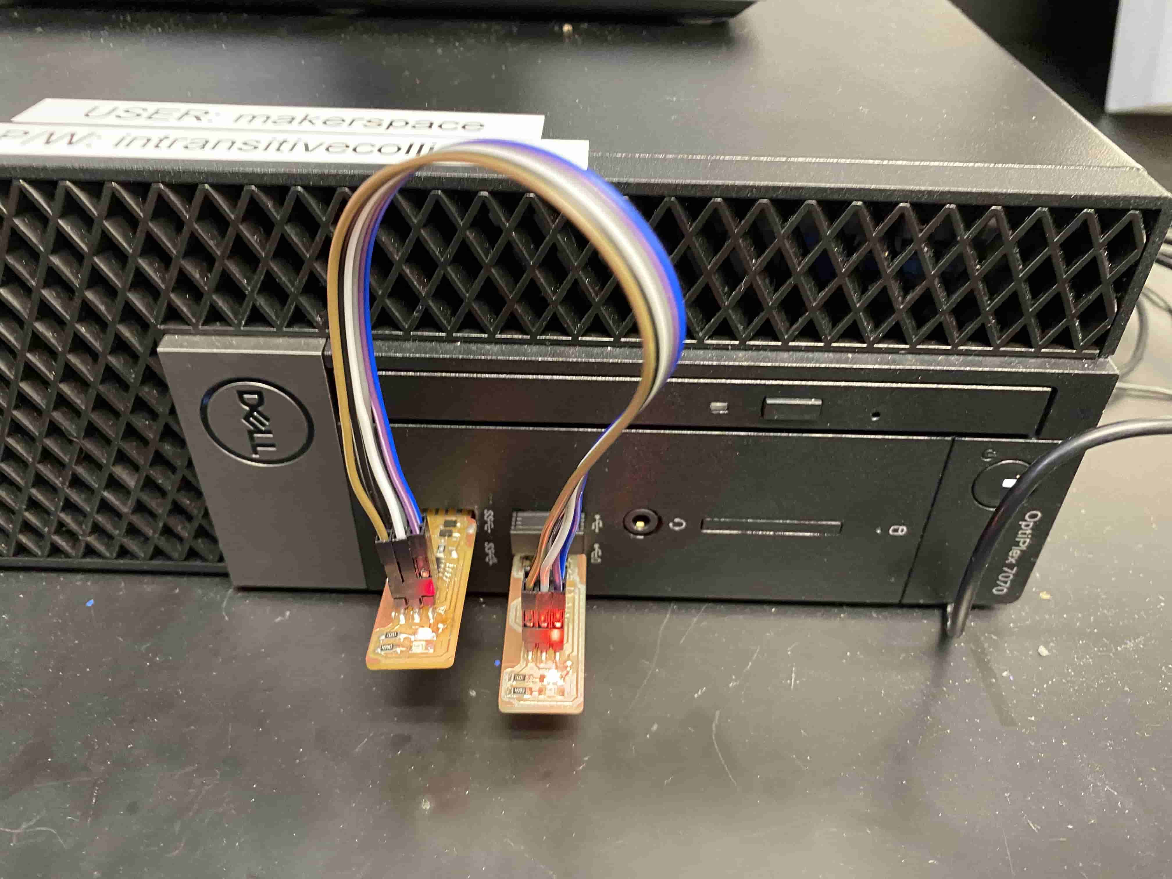
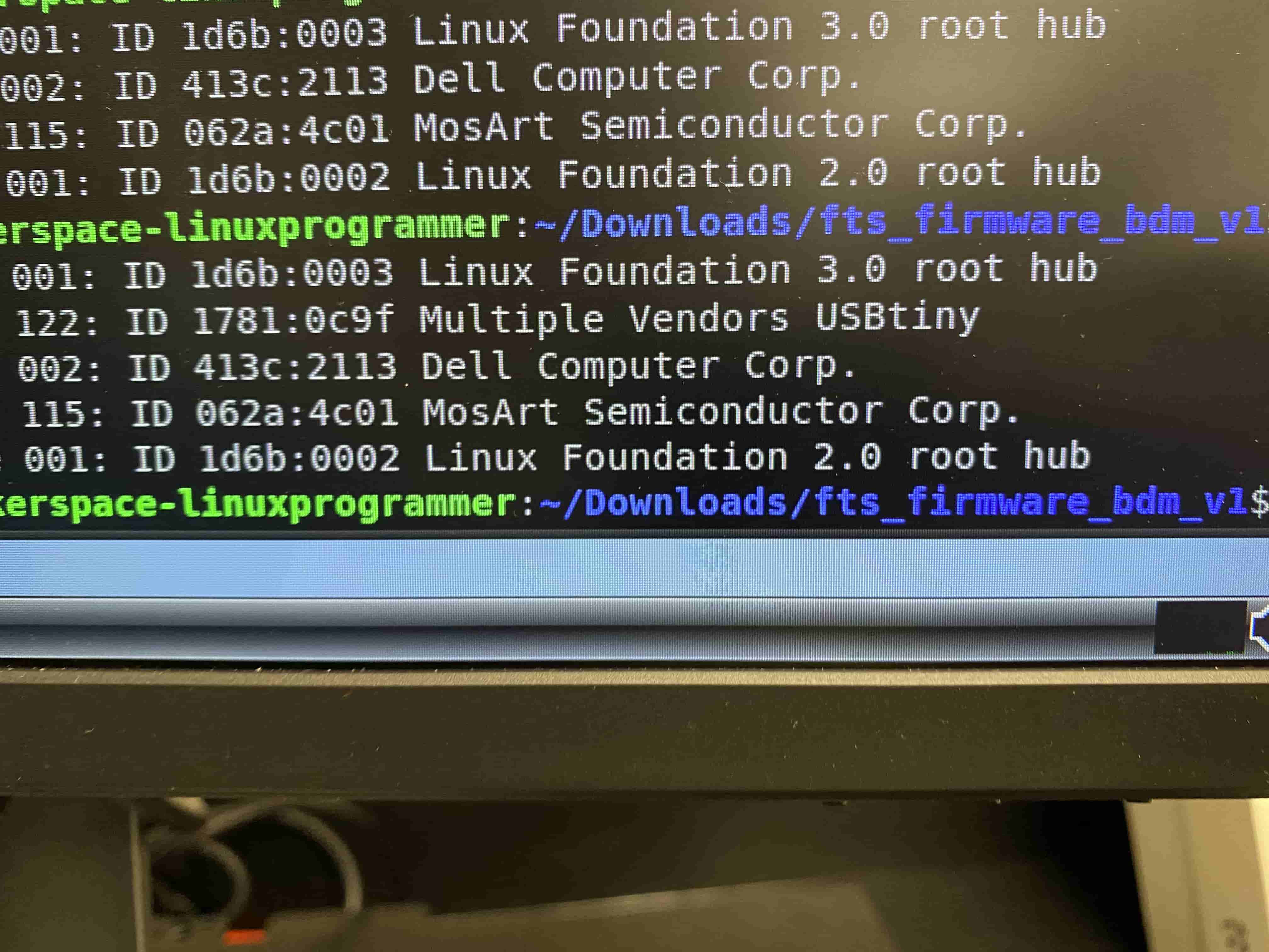
After plugging both of the FabTinyISPs and seeing both of them are showing red light, I typed "make flash" on the command line in terminal and this uploaded the information from the other FabTinyISP to my FabTinyISP. After finishing this I have typed "lsusb" to check if the computer is seeing my computer or not. Unfortunately as I mentioned before, one of the prblems I faced this week was figuring out why the computer isnt recognizing my FabTinyISP. At first I thought it was because maybe my USB part wasn't that good so, I cleaned up the soldering a bit and tried again but it still did not work, then I realized that, someone else gave me the 499 Ohms resistors and I never checked if they were actually 499 Ohms. When I checked they turned out to be 499 kOhms and that explains why the computer was having problems recognizing my FabTinyISP. I went back to soldering and fixed it and came back and tried lsusb again and it worked!
After doing lsusb I got this, as you can see it says Multiple Vendors USBtiny. That is my FabtinyISP.
When I saw my FabTinyISP I was assured that it was working and now I typed "make rstdisbl" to burn the reset fuse on my FabTinyISP. The reason to do this is because, if you don't burn the reset fuse your FabTinyISP can always reprogrammed or can be override by some other programmer. To prevent this and to be able to program other unprogrammed FabTinyISPs I burned the reset fuse. For the final step I went back to the soldering station and take the solder bridge on the jumper down.