Assignment:
Group Assignment:
1# Characterize your lasercutter
2# making lasercutter test parts
3# making test parts that vary cutting settings and dimensions
Individual Assignment:
1# Cut something on the vinylcutter
2# Design, make, and document a parametric press-fit construction kit, accounting for the lasercutter kerf, which can be assembled in multiple ways
Brainstorm
Softwares:
 - Fusion 360 - A CAD software that allows both 3D and 2D designing
 - Adobe Illustrator - a great software that allows editing and manipulating vector images
 - Sure Cuts a Lot - it is a Vinyl Cutter Software that allows you to trace images and cut them out
Machines:
 Vinyl Cutter
 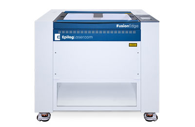 - Laser Cutter
Another tutorial where I talked more in Depth about vinyl cutting:
Group Assignemnt
To characterize our laser cutter we did multiple tests on it. Because our laser machiene is few years old, the specifications on what settings to use for different materials are not accurate anymore. Hence, doing these tests allows us to have better insight on how powerful and accurate the lazer cutter is. As a group we did 2 different tests: Kerf test and Vector/Raster Settings. Kerf is the diameter of the laser beam. Finding the Kerf is important if you want to have accurate parts to at least 3 decimals. The Vector/Raster Settings are important not because they are the main functions of a laser cutter but also because of safety reasons. If a user uses 10% speed, 100% power, 100% frequency on paper is can start a fire. Hence, finding the optimum settings for each material is important. For our group test we have used cardboard to do the tests.
Kerf Test:
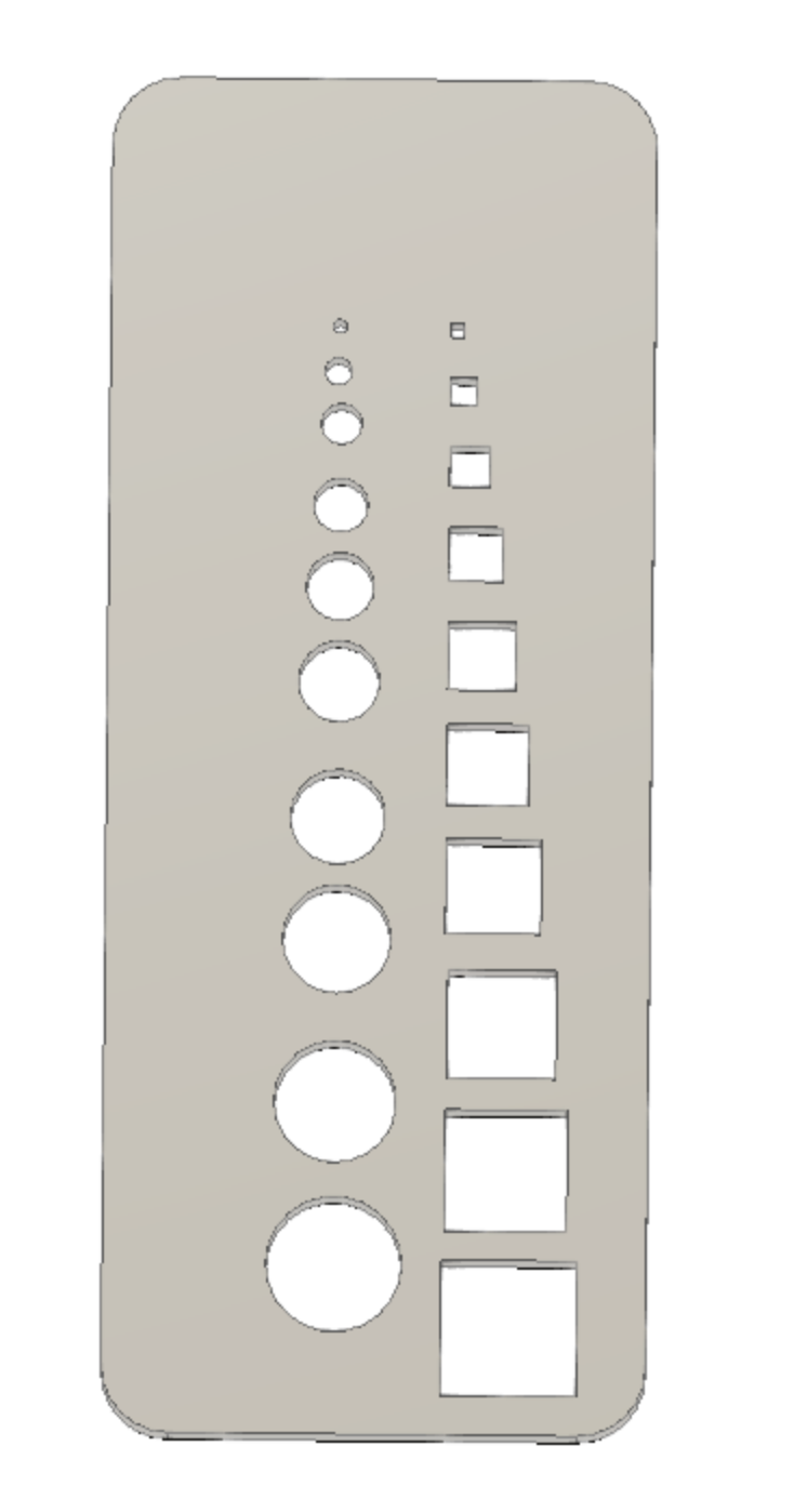
For the Kerf Test we have went to google and found how people did their own Kerf Tests. After researching a bit, we have designed a Kerf Test which includes square and circular holes ranging from 1 mm to 10 mm.
Instead of exporting the sketch as a DFX file and then opening it up on Adobe Illustrator, we can use Fusion 360's built in Manufacturing tab to the Computer Aided Manufacturing (CAM). Using the Manifacturing part of Fusion 360 you can take your design and upload it to any machine from a CNC mill to laser cutter.
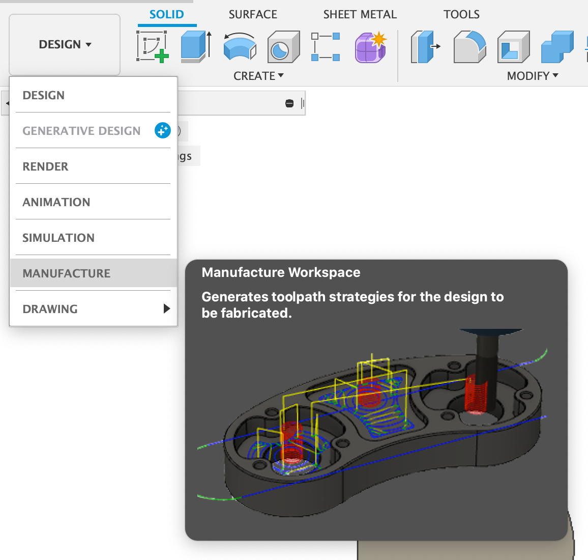
In Manufacturing when you go to Fabrication Tab and then click to cutting tool, it will open a new tab wheere you can select which part of your object to be cut. On top of that you can select which tool and software to use. Because I am using an Epilog laser cutter I will be using their software and using a laser cutter as a tool.
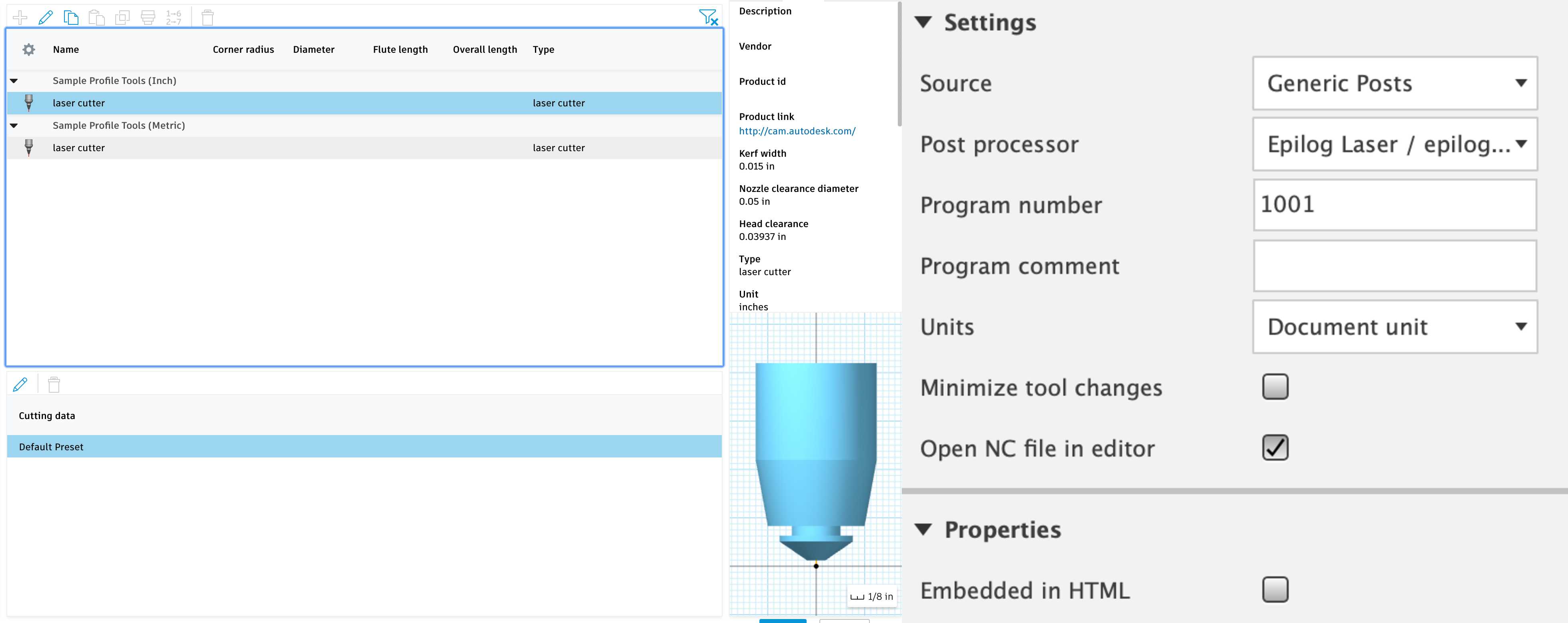
After selecting all your options you should click ok and the Fusion will create a tool path as you desire. The reason why this is really powerful is because while selecting a toll rather than selecting laser cutter as a tool you can modify it's kerf value with the actual Kerf value of your own laser cutter and you will get precise cuts.
Unfortunately, when we finished the manufacturing process, Fusion was not able to detect holes smaller than 5 mm. Hence, our Kerf test, ranged from 5 - 10 mm. The reason for this was the toolpath movement. After minimizing the toolpath movement we were able to get down to 3 mm holes but not till 1 mm. The reason for this is because our Kerf is too big. Hence we moved forward with only holes ranging from 3mm to 10 mm.
Finally, after exporting as an svg file and editing on Adobe Illustrator to add text we got this:
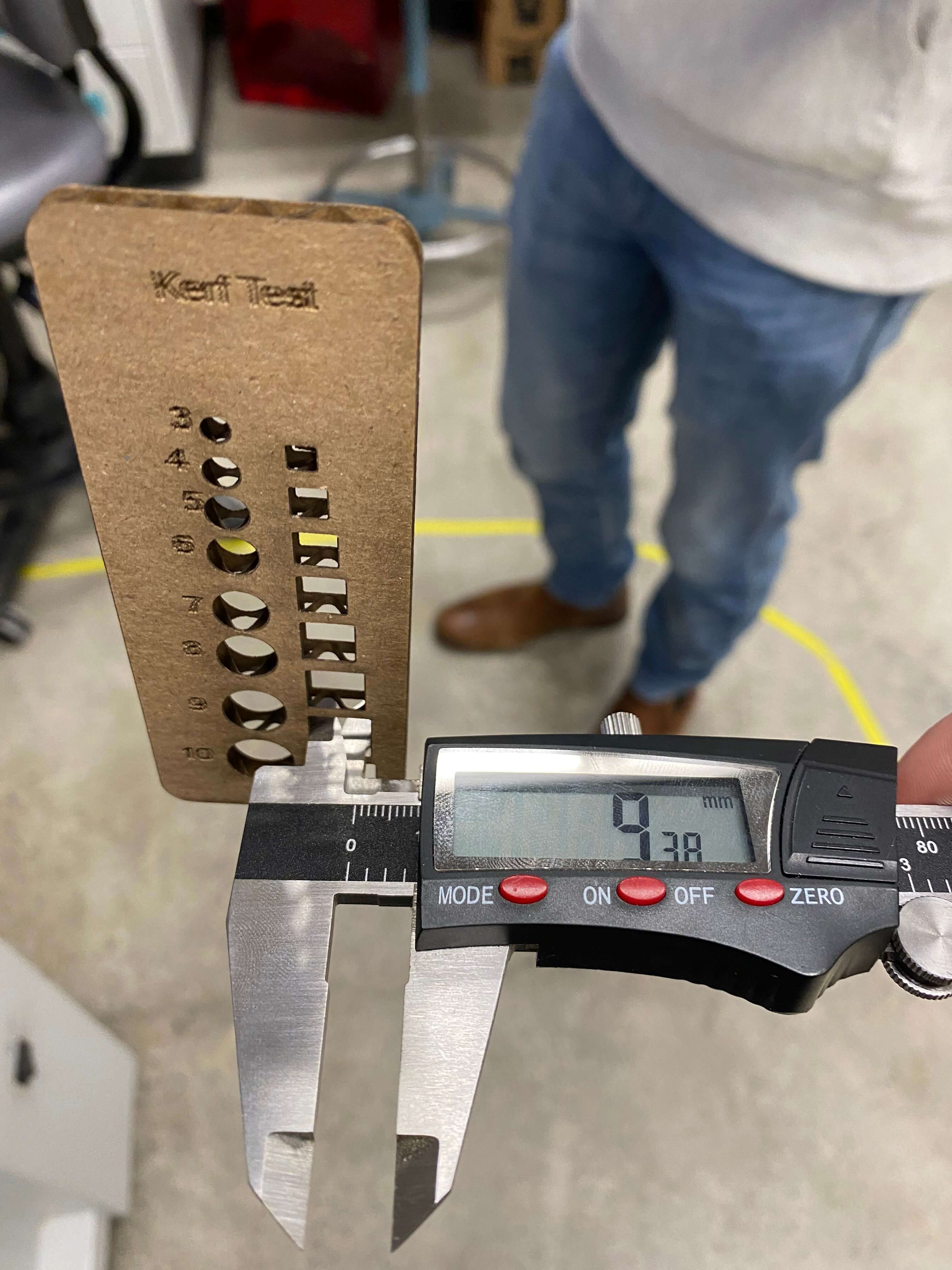
After geting the measurements from our Kerf Test We got these results:
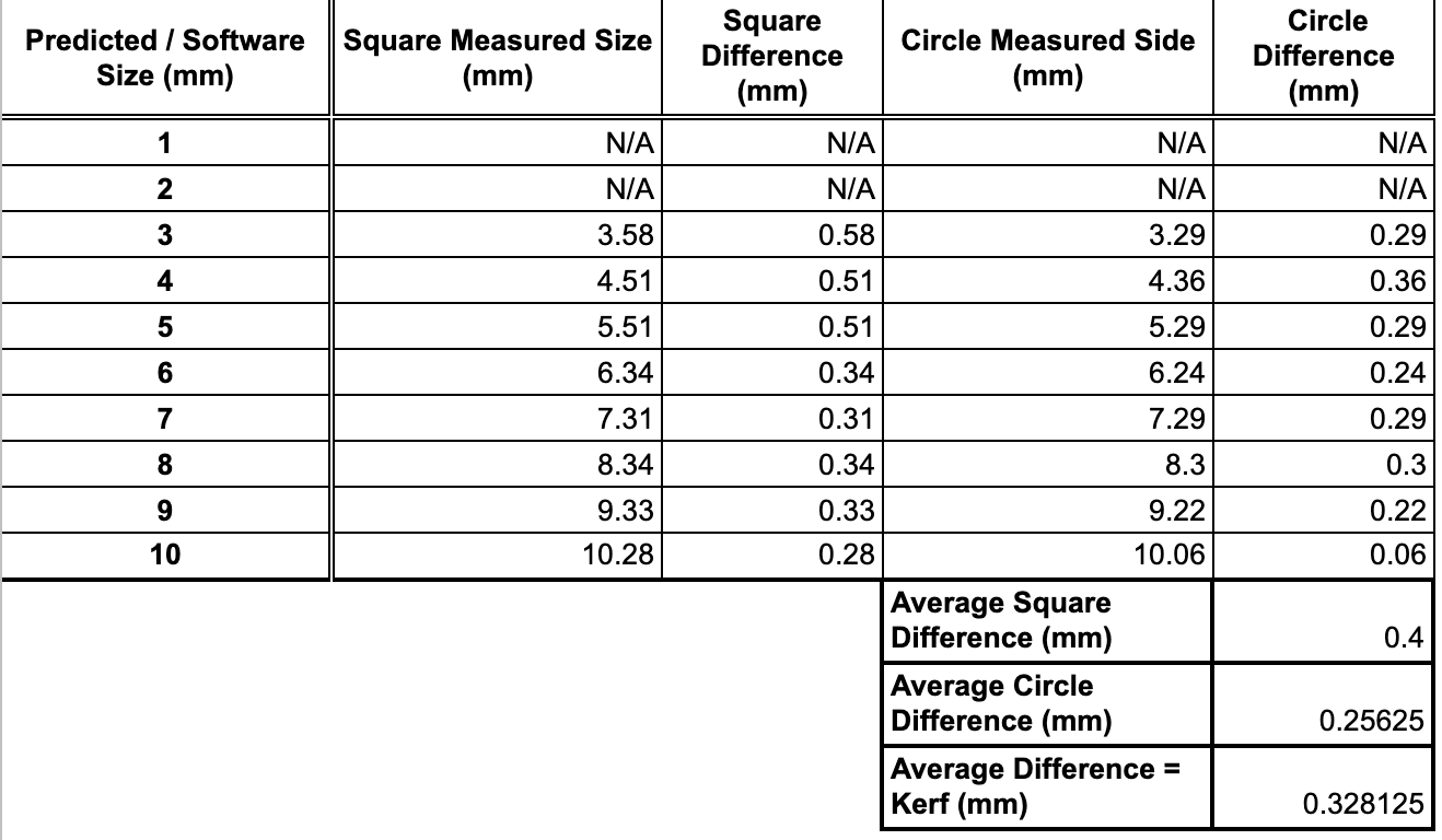
Moreover, as you can see after Kerf test results we found the kerf as 0.328 mm and on Fusion we set it as 0.015 inch which is 0.381 mm. Hence, we were off by 0.053 mm .
Vector/Raster Settings
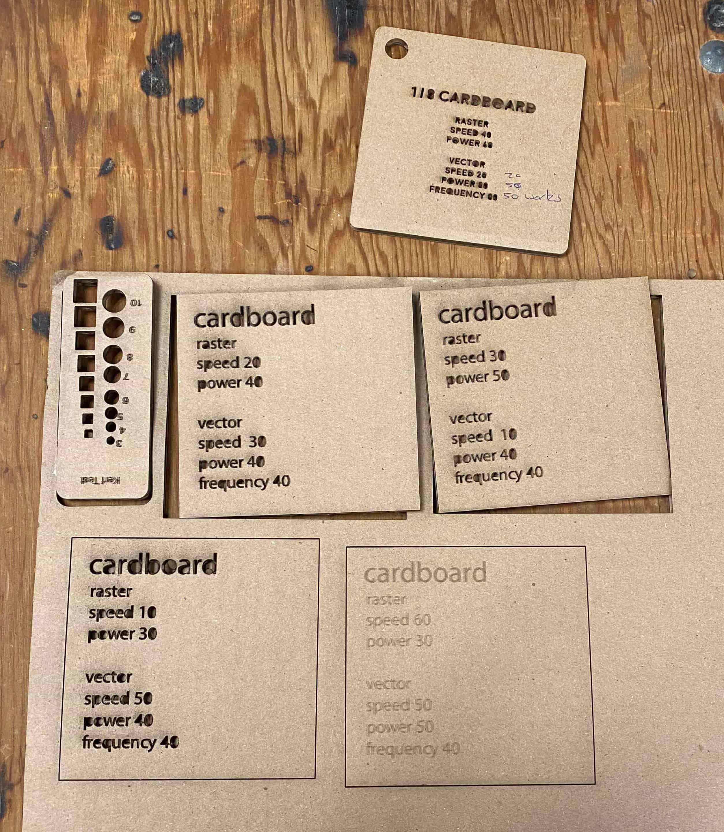
We have created square that contains the Vector and Raster Settings for the laser cutter. This way every time we cut a piece of that square it will also say the vector and raster settings of it and so we can deduct if it was succesful or not or maybe an over kill.
By using this method we can conclude on a perfect setting for the material used in our laser cutter. This also allows to mitigate the risk laser cutters posses such as being a fire hazard.
We first started by creating a square that contains spaces for Raster and Vector Settings on Adobe Illustrator.
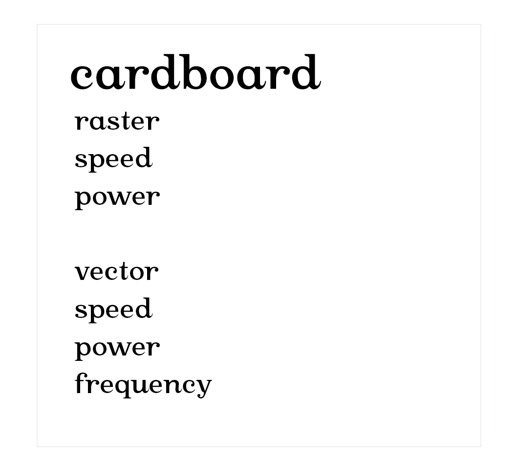
Now whenever we changed the Raster and Vector settings on Epilog Laser Cutter CAM Software, we can change the values on the the thing we designed and this will represent the results.
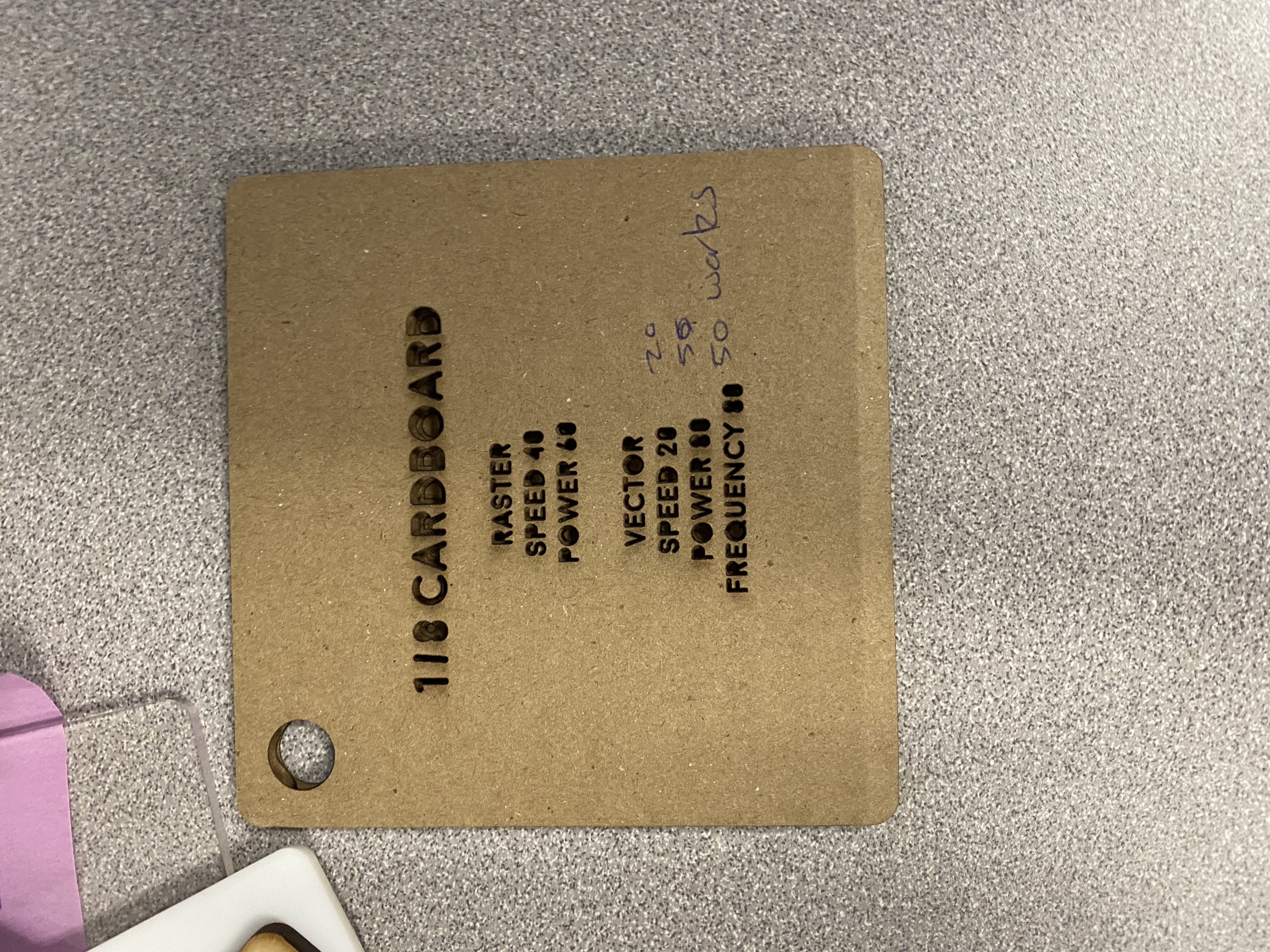
After cutting many we have concluded on that the best Raster & Vector settings is Raster: (Speed: 40, Power: 60), Vector: (Speed: 20, Power: 50, Frequency: 50).
Specs about our Laser Cutter
In our lab we use the Epliog Fusion Pro 48 CO2 Laser Cutter. The dimentions of the laser cutter is 48" x 36" x 12.25". However, the cutting area is smaller and somewhere are 46" x 28" x 10". This is because we have an extra bed inside the laser cutter that allows better airflow and less resistance to back fire caused by burning the fume coming out of the material while laser cutting. The Epilog company sells CO2, Fiber or dual source laser cutters but ours is CO2. Ours is 80 Watt CO2 Laser Cutter. Because ours is an old model it does not have cool things such as IRIS Cameras which helps you position your material according to your artwork. In our lab we only do vector cutting in our laser cutter with non-toxic materials that are smaller than 1/4". To operate the laser cutter, first we need to create a file or take an black and white SVG file from internet. However, we need to import this SVG image to Adobe Illustrator. From there we can just print it out using the Epilog Fusion Printer. The computer recognizes the Laser cutter Software as a normal printer, hence, when you send your file to that printer, rather than directly sending it to the laser cutter, the computer first sends it to the Epilog Laser Cutter App.
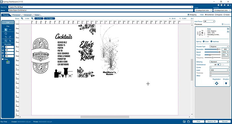
As you can see from the images, you upload your images from Adobe Illustrator to Epliog app via print and it appears in the Epilog App. To differentiate between a vector cut and raster engraving, the Epilog App looks at the thickness of the traces and decides what is for engraving and what is for cutting. On the left side you can chose the power, frequency and speed settings for vector and raster. After you are done, you can put your material in the laser cutter and click cut in the epilog app. This sends the file to the laser cutter how ever does not starts the laser cutting. Before starting cutting, we need to position our origin point, first we do the Z axis. We do this by using an 4" indicator that goes on top of the last mirror on the laser cutter. the moment it touches the material we stop raising the Z axis up. After that we remove the metal part and start jogging our laser head to the correct position and once we are at the correct position, we click on the joystick to set it as the Zero. after that we go to Job menu on the laser cutter and click GO.
Individual Assignment
Vinyl Cutter:
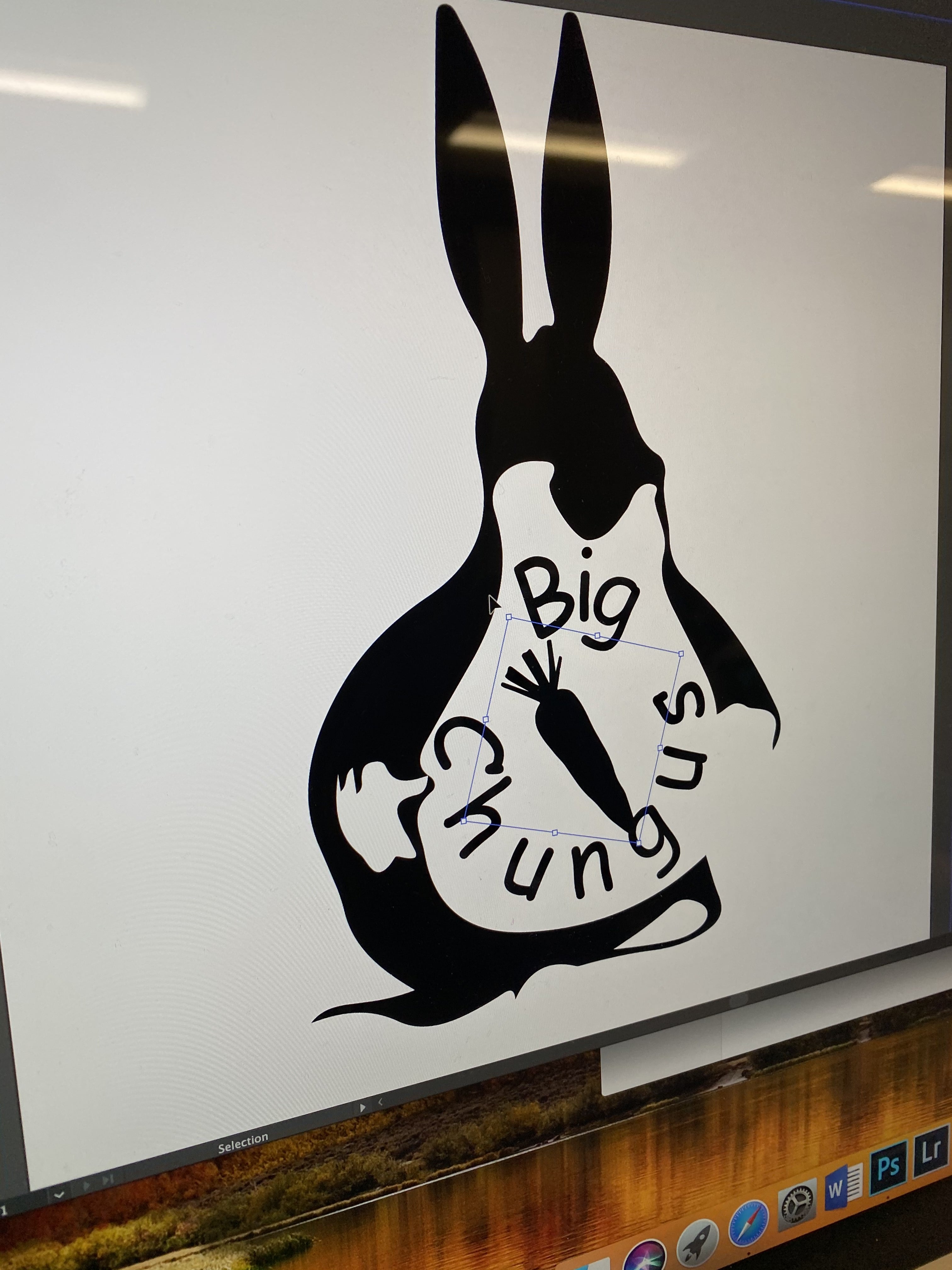
I always wanted to have cool stickers over my computer like everyone else but I was just never able to find a sticker that I really liked and valued to put on my computer. Since I would be using my computer really frequently, I want it to be something that I can at least not be emberassed of. Hence, I decided to use the logo of our Fab Academy Group. Our group name is Big Chungus (Yes from thee Meme). You could ask how can a sticker Big Chungus would not be something to not be emberassed of. Well, the reason is because we have designed as a modern version of it. Using Adobe Illustrator's "Silhouette Image Trace" method we can get cool black and white futuristic vector images.
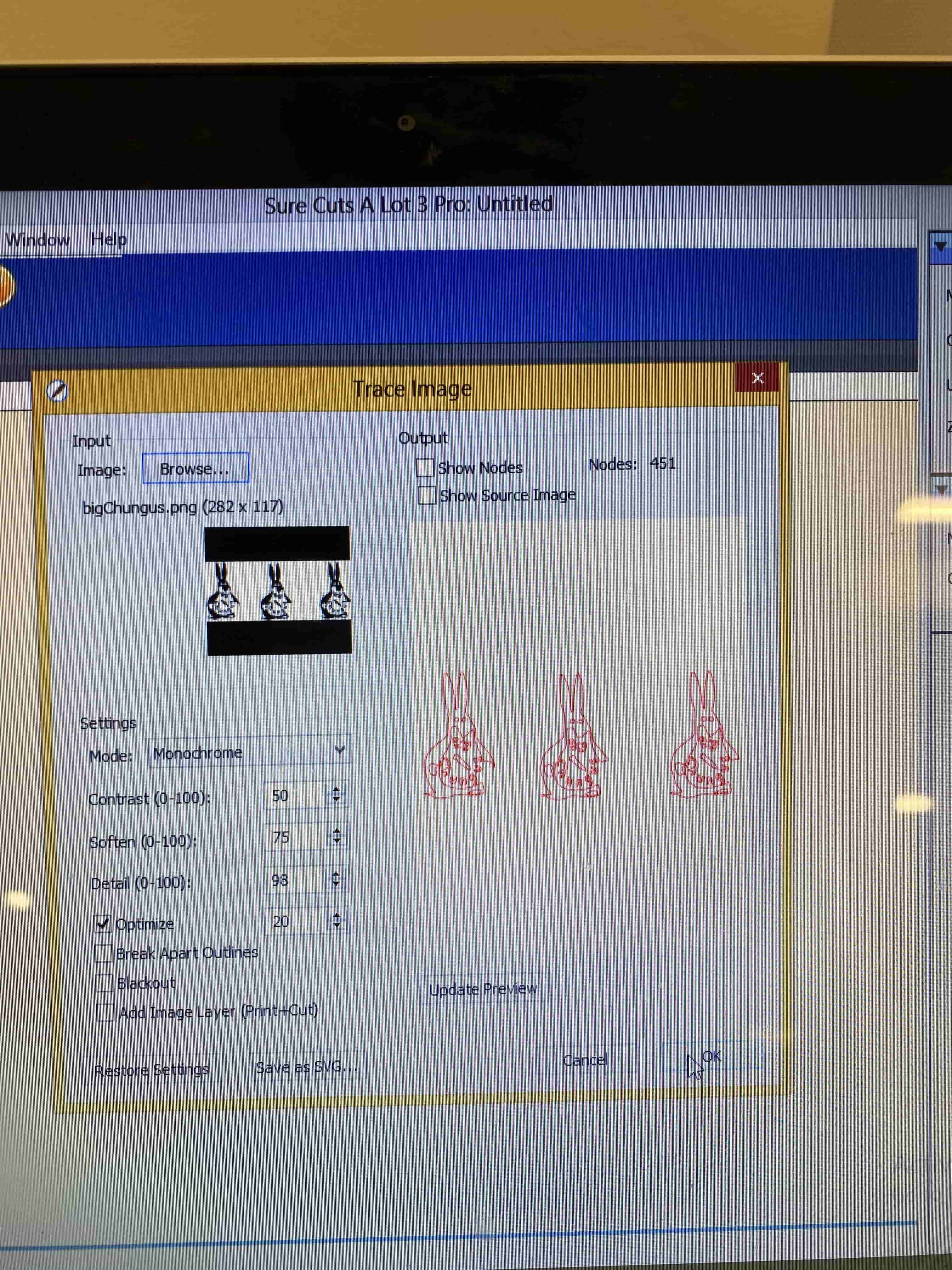
After Designing it we sent it to Vinyl Cutter Software in which we opened the svg image we sent using it's own image trace option. This allowed the Vinyl Cutter software to turn our svg image into a an another vector image which represents the path the blades will take.
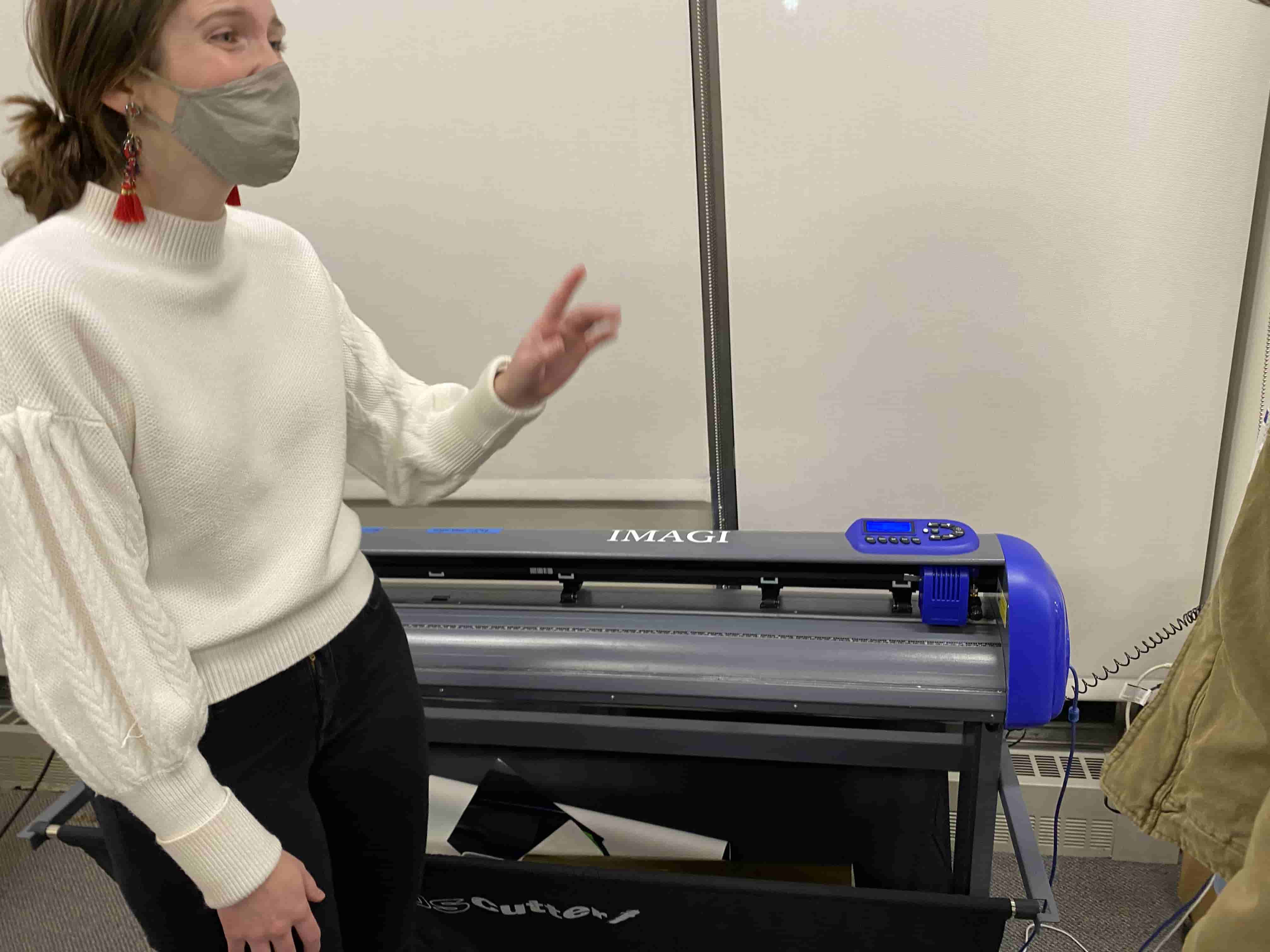
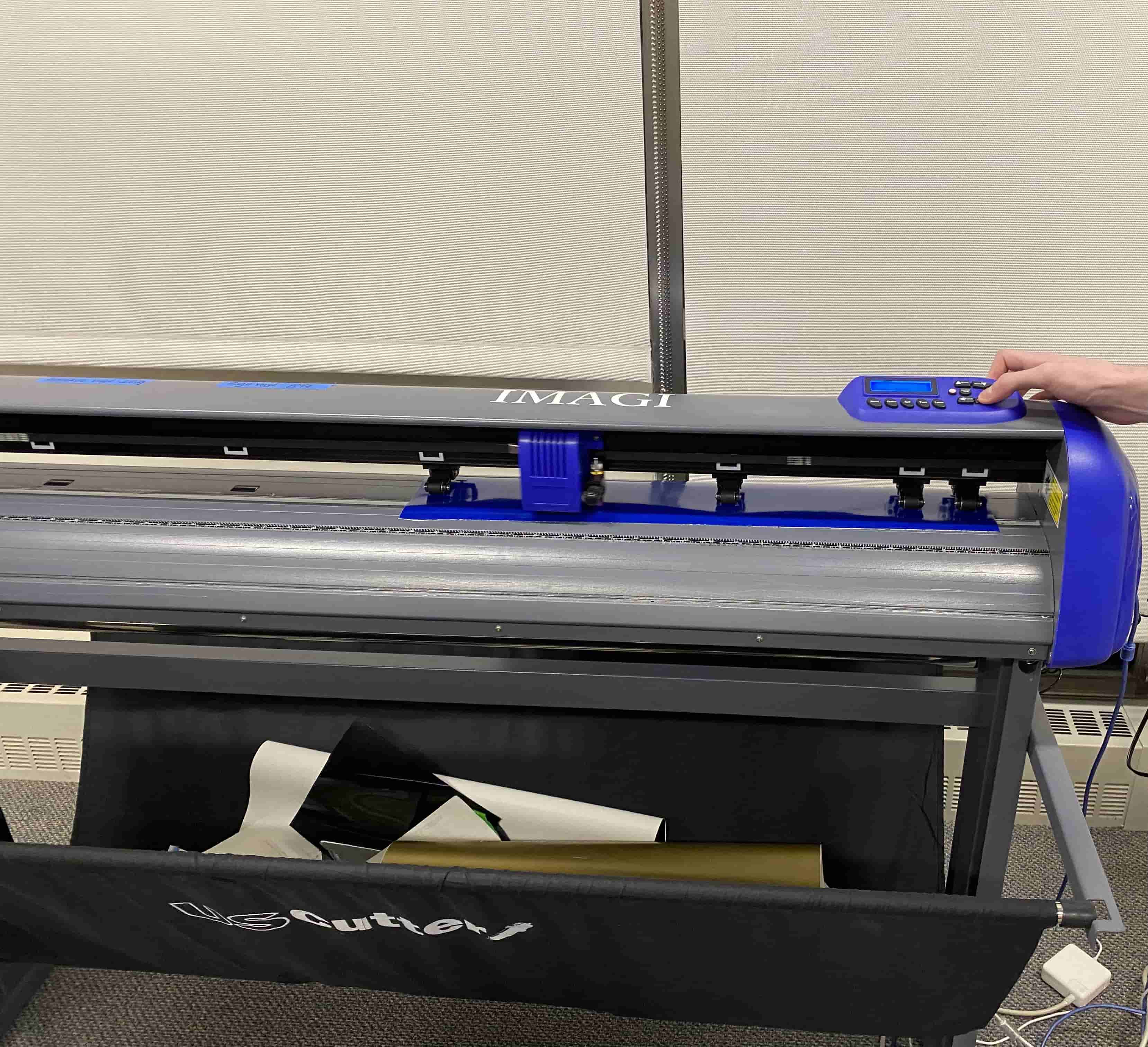
Before cutting the Vinyl, we had to set the Vinyl cutter to specific force and speed according to the material we are using. We were using Sign Vinyl so we used 84 grams of pressure in our Vinyl Cutting process. Another step before cutting is to put the Vinyl Correctly into the Vinyl Cutter and set the home position.
After the Vinyl Cutter cut out the Big Chungus, I have removed the excess Vinyl and it looked like this:
After using a transfer tape and some plastic tool I have transfered it to my computer.
Modular Construction Kit:
Modular Construction Kit in its basic sense is a Lego. Like Lego Modular Construction kits are made from components that fairly has the same preferences and apperances that can combine together to construct other stuff.
For this assignment, I will be creating two types of piece that can connect to each other. I named them as joints and arms. I designed them and then exported them as laser cut svg using Fusion 360.
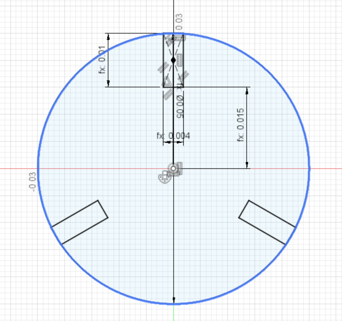
Initially, I have started manufacturing the joint piece. For this, I have started creating some parameters like the thickness of the material I am using for this kit or the depth of each slot for pieces to come together.
After creating parameters I have created a circle with 5cm in diameter and created rectangular slots using the parameters I have created. This part will be the used as joints to create more complex structures.
After creating the joins I have created the arms. For this I initially created a rectangle 5 by 10 cm and then added 2 circles at the end of it and then added slots to it as the same way as the joints.
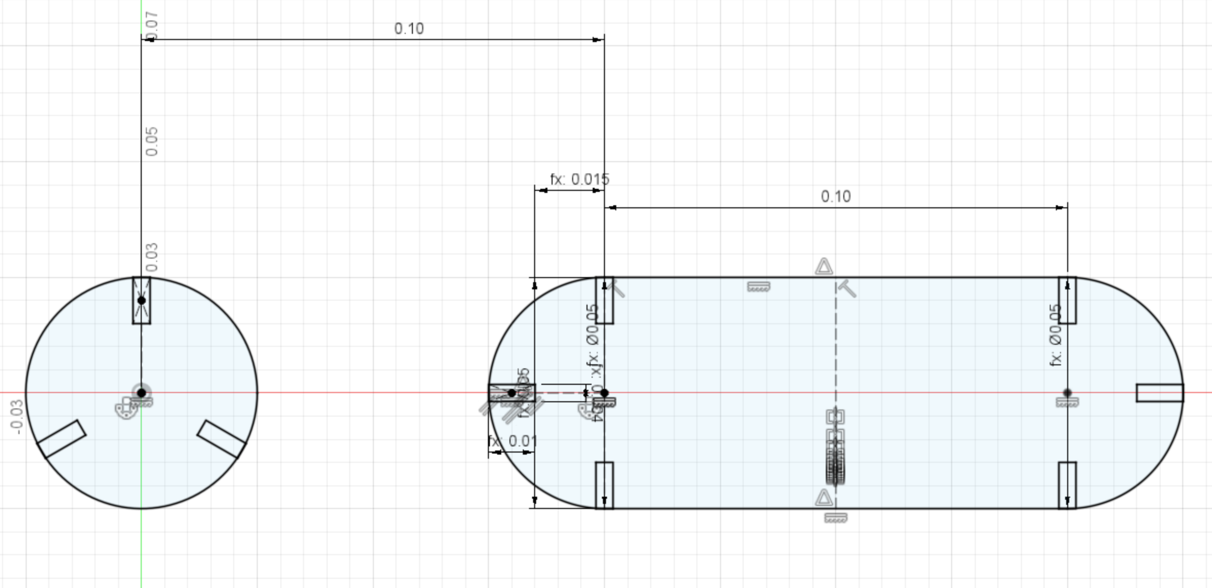
To make my design perfectly stable I have used the constrain tools. Later, I have extruded it and used the same steps as the Gropup Assignment Kerf Test to turn the parts to svg image.
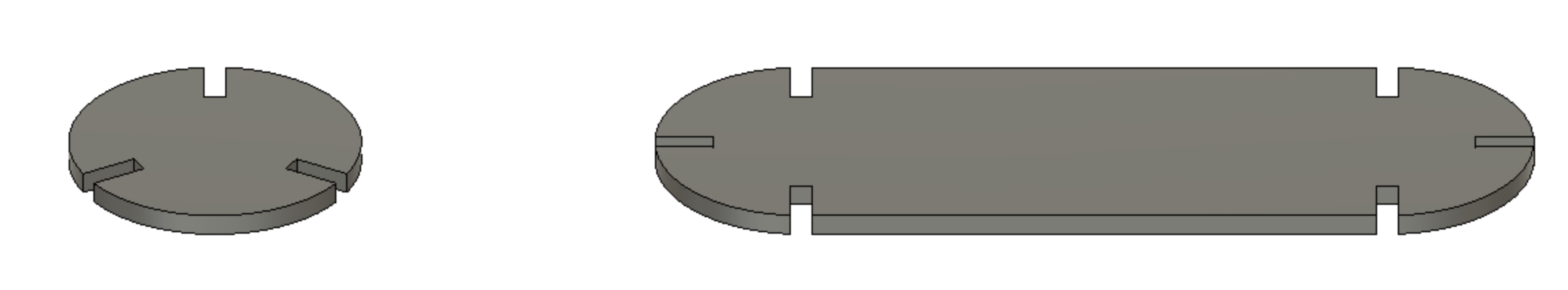

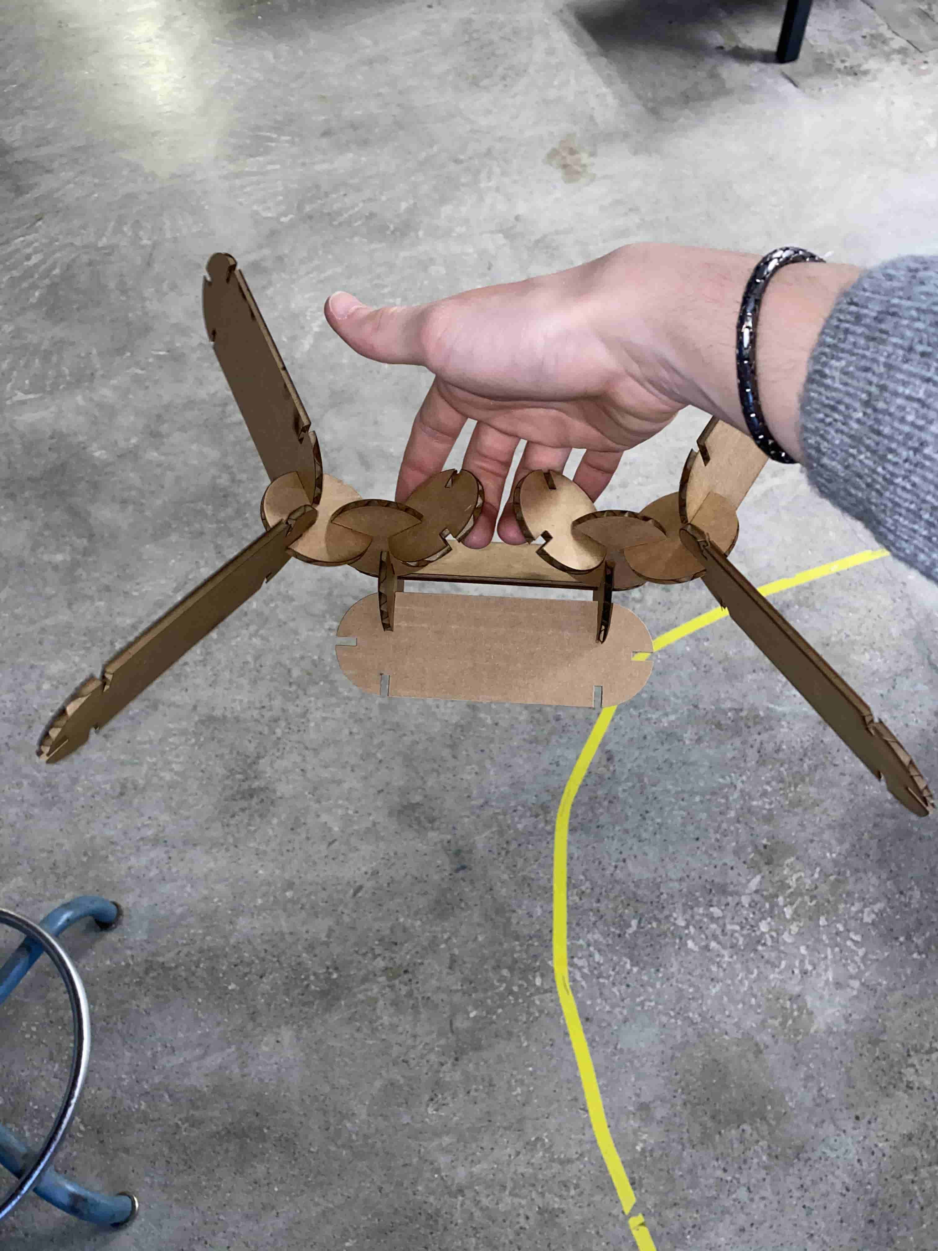
After using the laser cutter the pieces looked like this: