Week 3 Computer-Controlled Cutting
This is the first week we're working with machines! A summary of the topics is given below.
Summary
This week is all about Computer-Controlled cutting. We learned to work with a laser cutter and vinyl cutter.
Assignments
Group assignment
- characterize your lasercutter’s focus, power, speed, rate, kerf, and joint clearance
- document your work (individually or in group)
Individual assignments
- Design, lasercut, and document a parametric press-fit construction kit, which can be assembled in multiple ways. Account for the lasercutter kerf.
- Cut something on the vinylcutter
Learning outcomes
- Demonstrate and describe parametric 2D modelling processes
- Identify and explain processes involved in using the laser cutter.
- Develop, evaluate and construct the parametric construction kit
- Identify and explain processes involved in using the vinyl cutter.
Project management
The following steps in spiral development:
| Spiral | Tasks |
|---|---|
| 1 | Characterize the machines (group assignment) |
| 2 | Test vinyl cutter with sticker material |
| 3 | Parametric design of cardboard object |
| 4 | Laser cutting parametric design cardboard |
| 5 | Vinyl cutter with copper material |
| 6 | Create instruction video of laser cutter |
| 7 | Bonus if there is time: vinyl cutter with drawing pencil |
This week’s results for individual assignments
Laser cutter
Vinyl cutter
Combined :)
How-to’s are below!
Laser cutter
The laser cutter in our lab is from BRM, originally a Dutch brand. It’s a big one! Because I went a little overboard with documentation in last week’s Computer Aided Design assignment, I decided to make a video to demonstrate the laser cutter at Waag. Note that every year, the settings change. So this can be used as a general guideline.
The video was made with Adobe Premiere Rush (first time!). It’s nice to try out settings and get some experience with video editing in preparation of the final project. It’s not perfect, but hey, it’s a start! The video was compressed with Adobe Media Encoder, from 95.2 MB to 6.7 MB. That’s why the resolution is very low. A link to the tutorials I consulted can be found on the Principles and Practices page from week 1.
Group assignment
Write down what you did as group, and specify what you did for the group assignment.
First, we divided the tasks for design:
- Speed x power (Nicole) test in cardboard, wood, acrylic
- More fluid shape (designed by Nadieh)
- Kerf test (designed by Erwin)
- Measurement tool (designed by Douwe)
- If time: Engraving (Nicole - was included in powerspeed test)
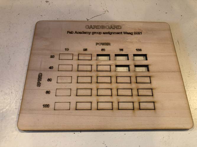
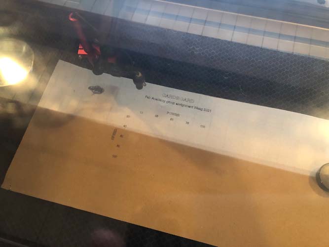
Power speed test
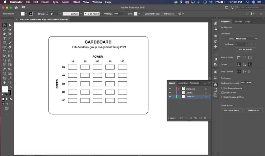
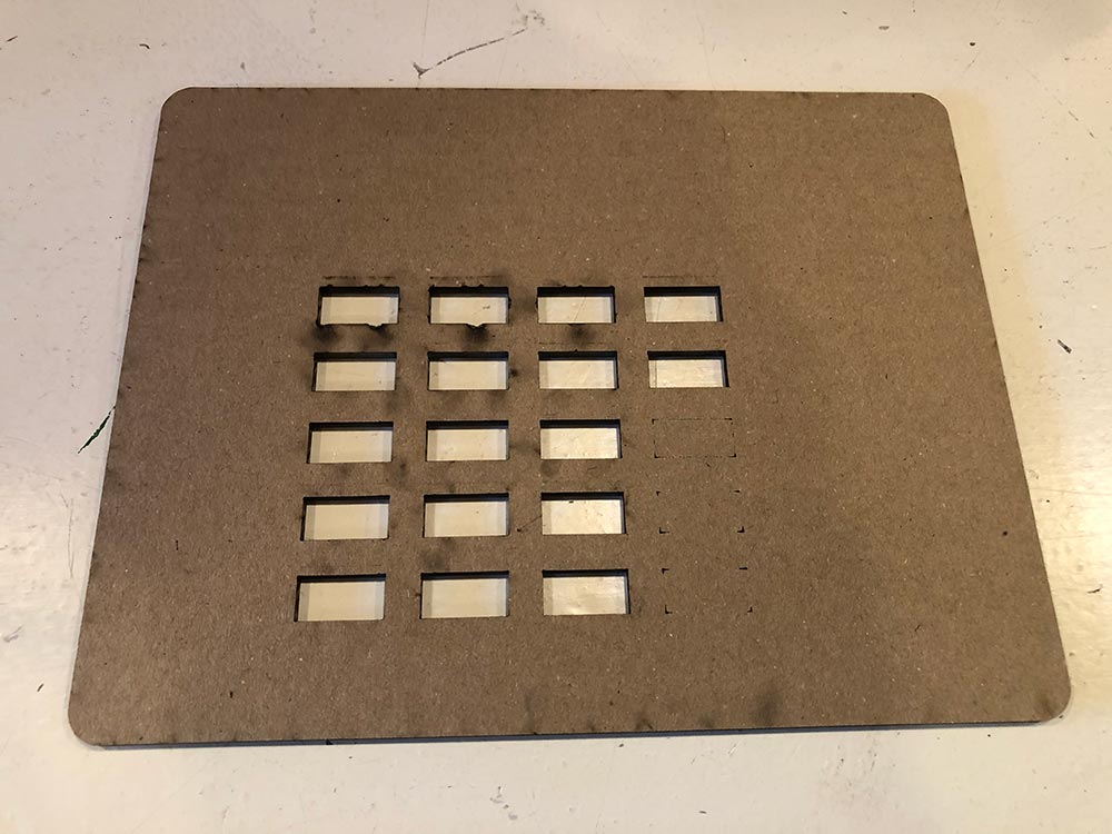
For the group assignment, I prepared the power-speed test file in Illustrator.
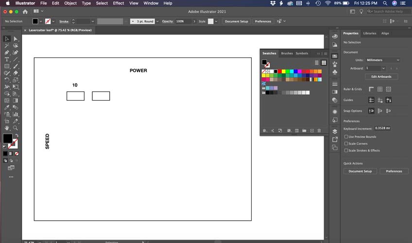
A useful tool for copying a shape multiple times is Transform Effect.
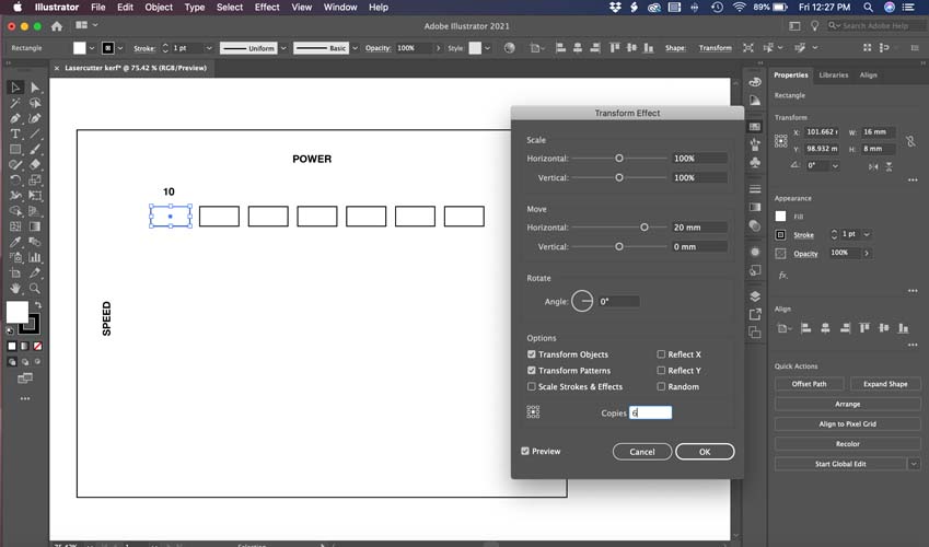
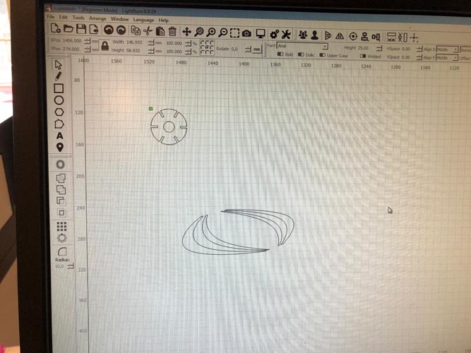
This is the completed design. Save the .ai file on an usb and open this in Lightburn.
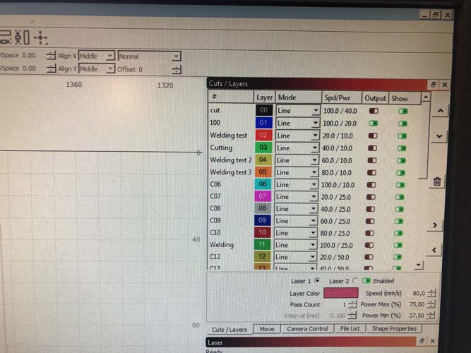
Preparing the file in Lightburn. Each line gets another color. This is very useful because it enables you to laser cut a file with a variety of different settings in one go. First, you only select the parts you want to ‘engrave’. Turn off all other lines. When that’s completed, you can turn on all rectangles. After that’s finished, you can turn on the outline.
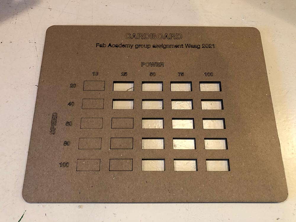
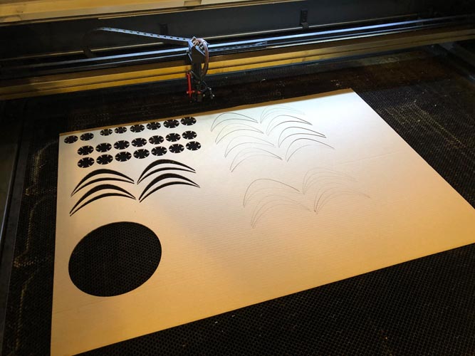
Cardboard test
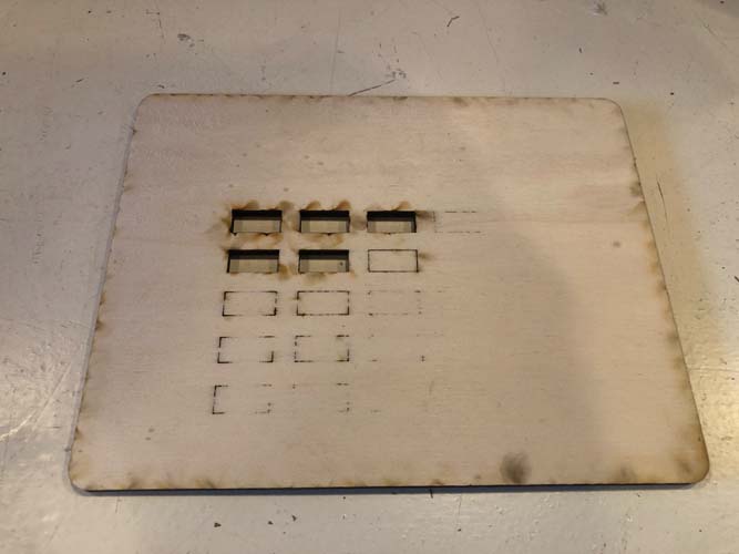
Plywood test
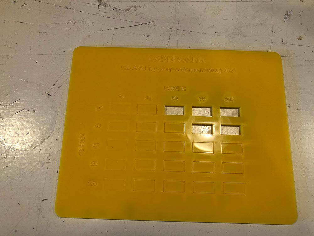
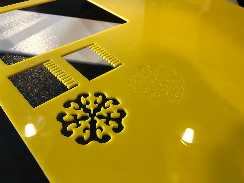
Acrylic test
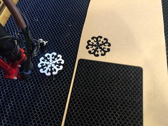
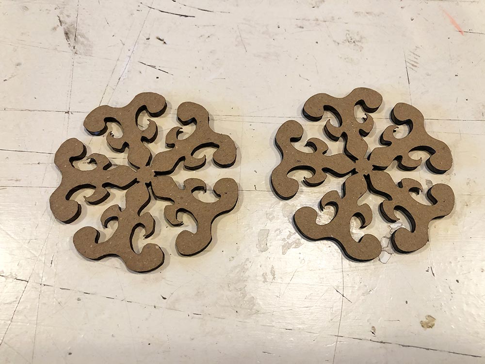
Fluid shape
Designed by Nadieh.
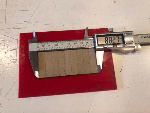
Kerf test
Designed by Erwin. For the kerf test we need 10 lines, thus 9 rectangles with a width of 10 mm. The kerf is then calculated as (designed length - measured length) / number of cuts.
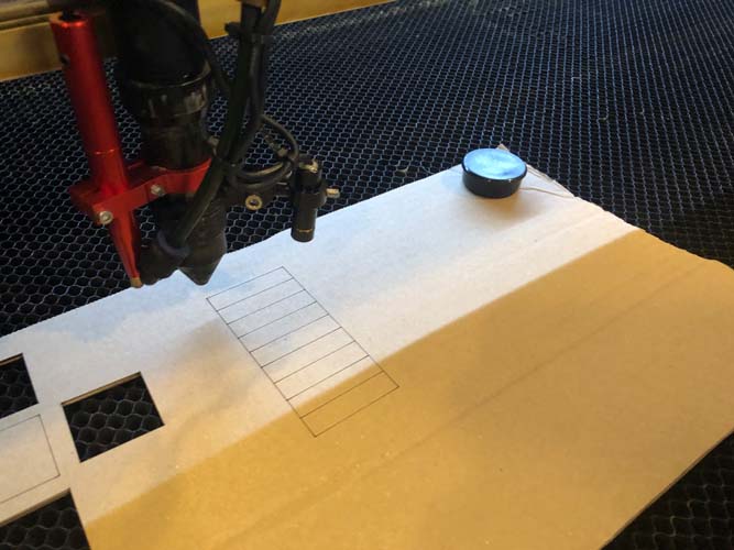
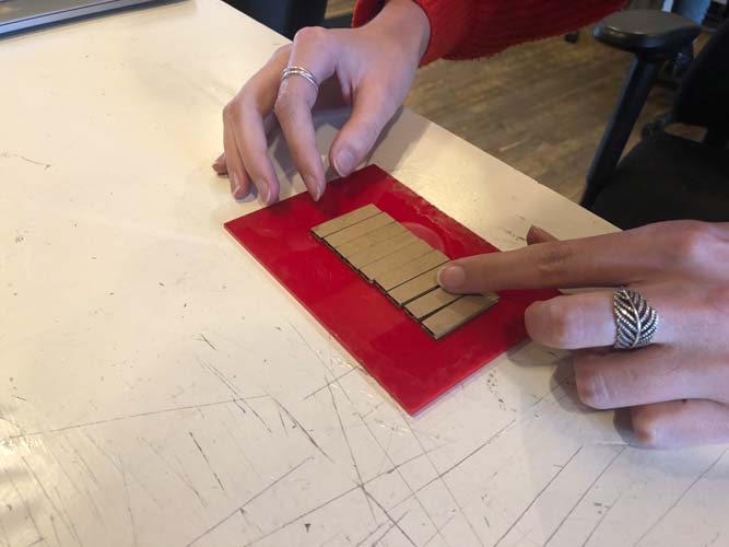
We accidentally cut the rectangles in the wrong direction. When you align the pieces in the left image, they shift on top of each other. Turning the cardboard with 90 degrees solved the problem, see the image on the right.
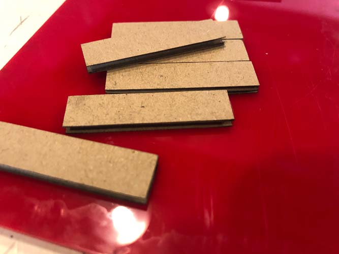
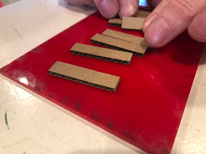
The length of the nine pieces is measured at 88.27 mm. Each piece is designed to be 10 mm, so theoretically they should add up to 90 mm in total. There is a difference of 1,73 mm. Thus, the kerf is 0,17 mm. We enter this number in the Lightburn software and use this setting for all other cardboard laser cutting projects.
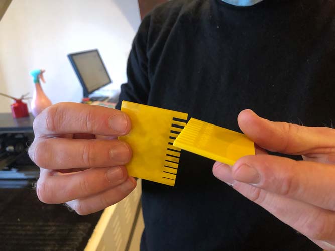
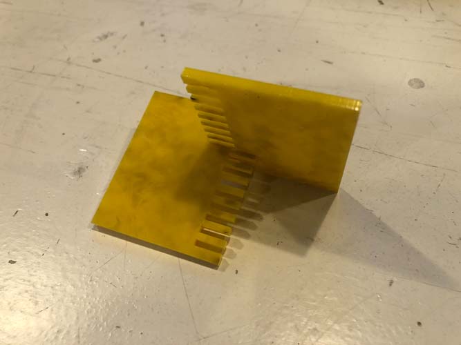
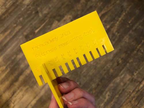
Measurement tool
Designed by Douwe.
Engraving
Next, I did an experiment with engraving cardboard. The first time, it failed! The speed was too slow.
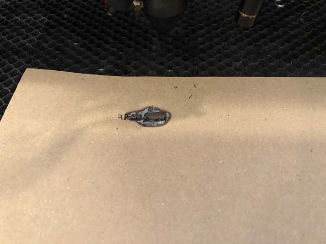
With the following settings, it succeeded.
- Speed 150
- Power 10
- Power 10
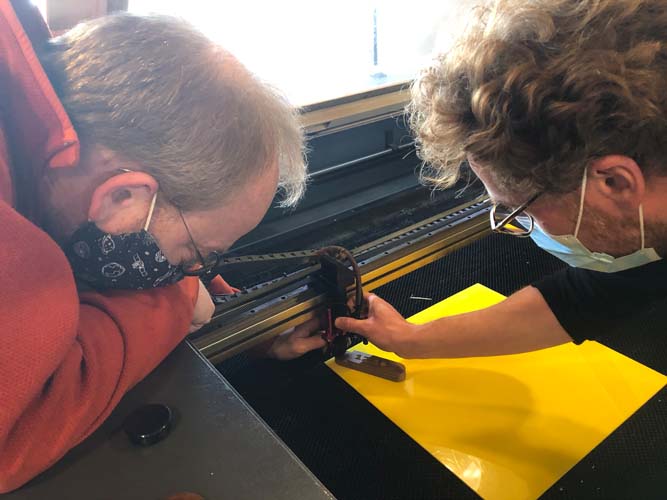
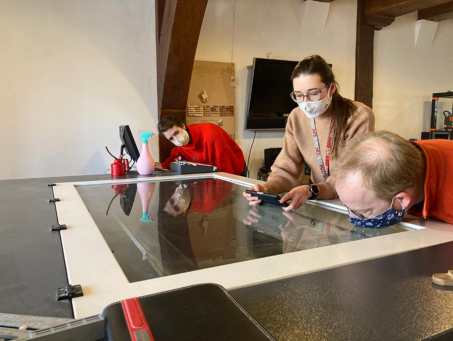
And finally, a snapshot of us in action!
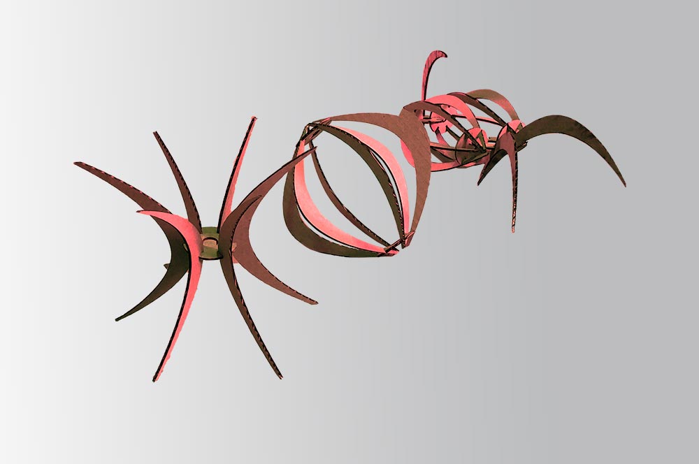
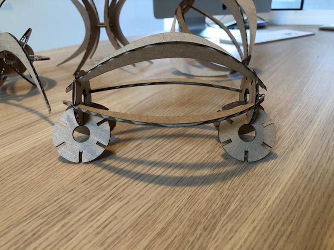
Press-fit construction kit
For this assignment, I decided to make a parametric press-fit kit inspired on laser cut lamp shades.
Parametric modeling processes in Grasshopper
Curves can be made in two ways, drawn in Rhino and drawn in Grasshopper. In last week’s assignment, I started with a curve in Rhino. I didn’t know it was possible to make one in Grasshopper. For completing this assignment, I consulted the following tutorials and resources.
This video on sectioning in Rhino shows how to make the file ready for laser cutting. Then I found out it’s possible to generate the same operations entirely in grasshopper with this tutorial from Parametric House. Again, the Delft University Grasshopper wiki pages came in useful as well. As a guidance, I also consulted the documentation of the press-fit kit from 2018 Fab Academy student Dhruv Saidava, see his page here. And the press-fit lamp shade from Nathan Melenbrink for inspiration.
Overview of results
Because there are a lot of screenshots, an overview of the results is shown first. The design consists of two elements: ribs and a connector. In the steps below, they are modeled from a base design.
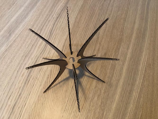
Ribs
Connector
Base design
Modeling the base design
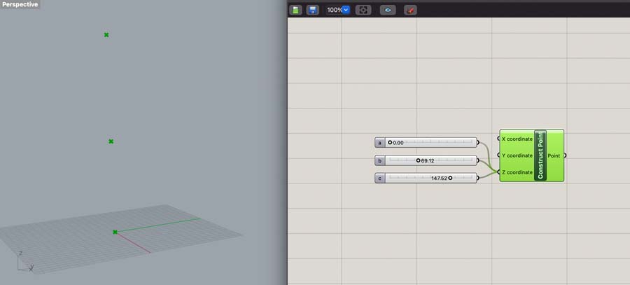
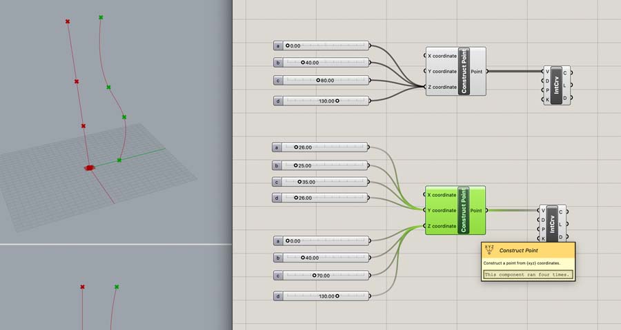
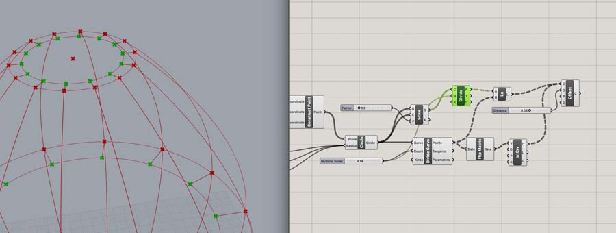
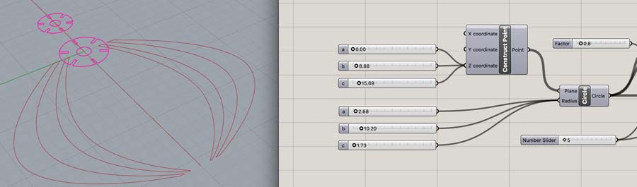
First, we start with the base design. Open a new Rhino file and type Grasshopper to open the interface. Double-click in the Grasshopper canvas to create a Construct Point component. Add three number sliders to the Z coördinate.
Duplicate this process to create more points, and change their positions on the canvas with coördinates. With Interpolate Curve you can connect the points with a line. This is a small experiment.
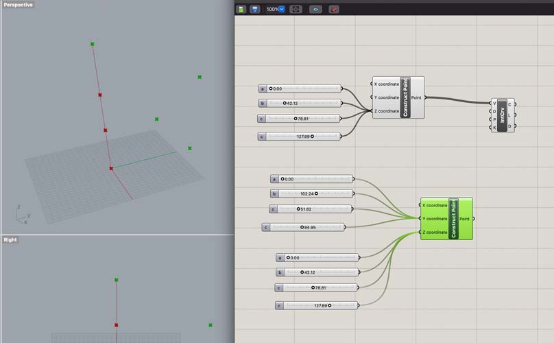
Do the same for the other points. Now we get the basic principle of creating curves from coördinates in Grasshopper. You can delete the second group of components before we move on.
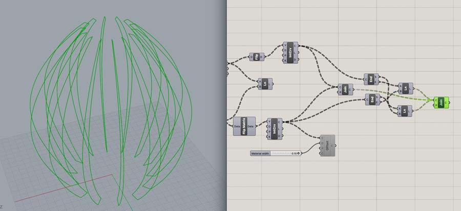
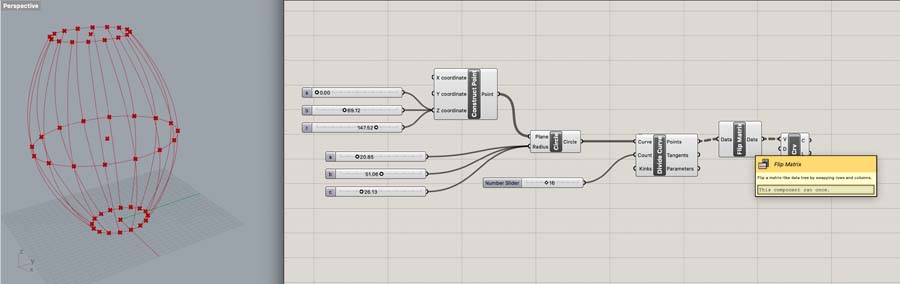
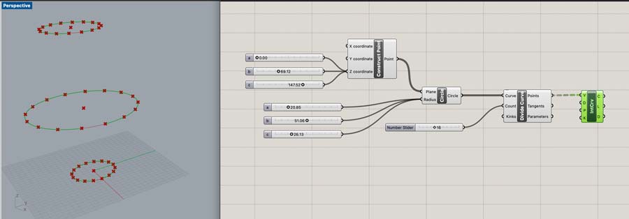
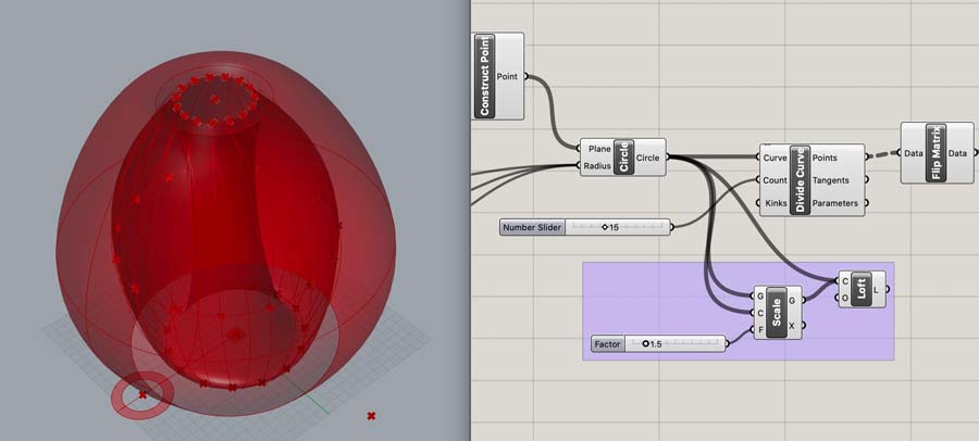
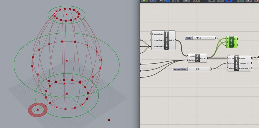
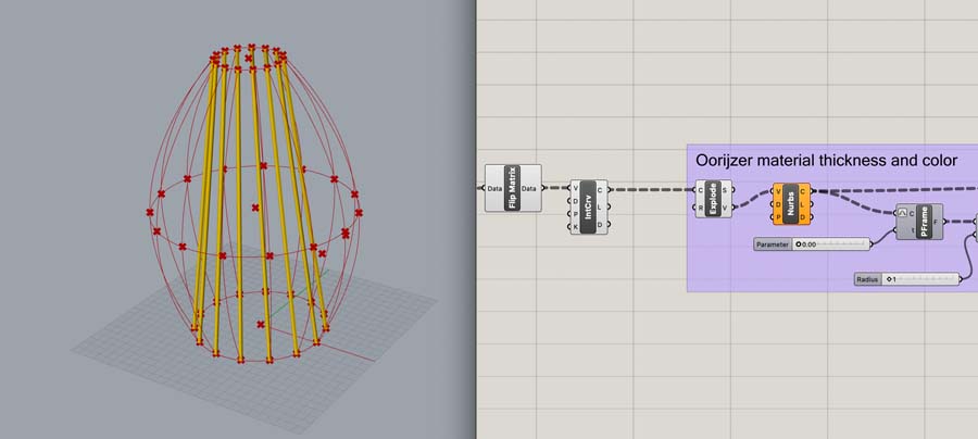
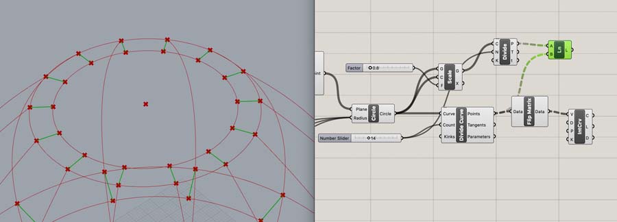
To create three horizontal circles, we delete one Z-coördinate value of the Construct Point component and add a Circle component. Rename the number sliders of both components to a, b and c. That way they correspond to each other. Add a Divide Curve component with a count of 16 to add points on the circle.
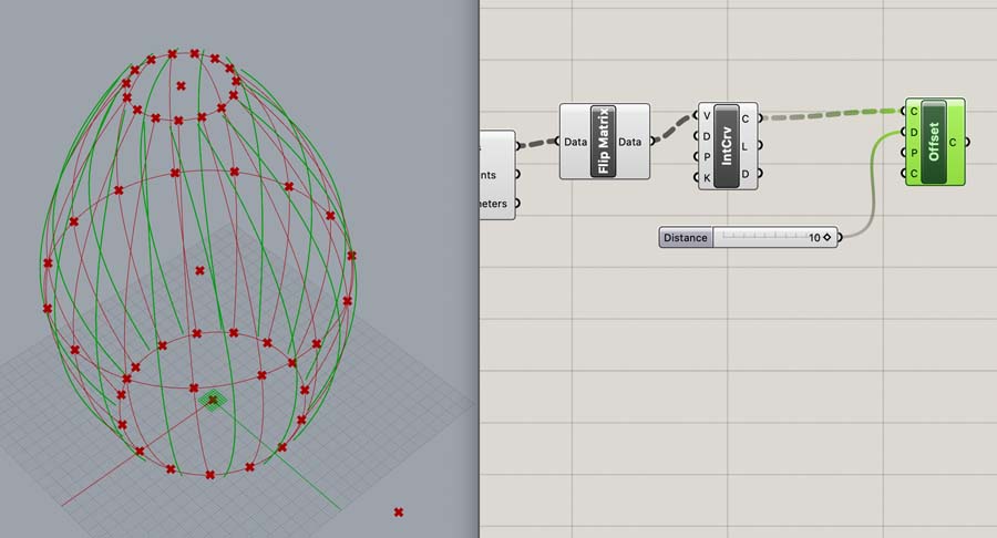
We then have to add a Flip Matrix component before we Interpolate Curve. This creates vertical connections between the points.
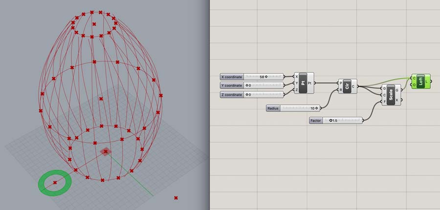
To get the material width I experimented with a couple of options, including Offset. This didn’t work because of its rotation.
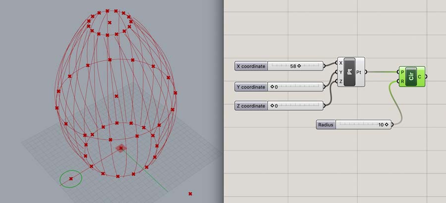
Then I tried another route by creating a small circle on the canvas, left from the design.
With Scale and Loft you can create an infill surface.
Then, I would copy a part of this code back into the main design. This generated a cool shape, but is not what I intended.
With the example code, I attempted to create the connecting element on the main structure. This was taking too long, so I decided to move forward by drawing this in 2D.
Modeling the connecting element
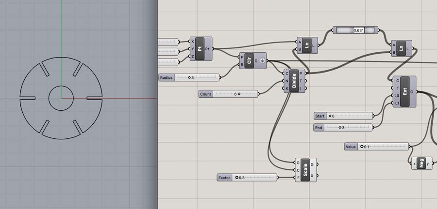
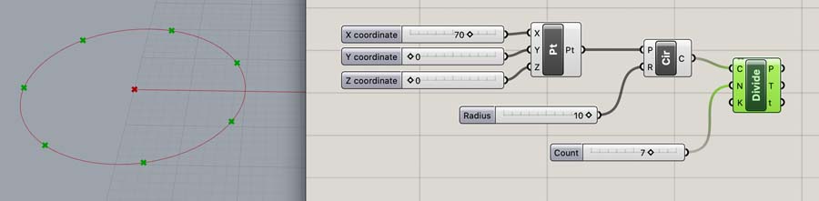
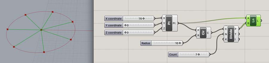
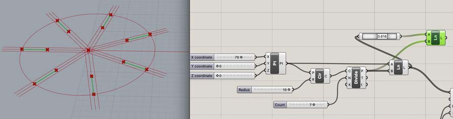
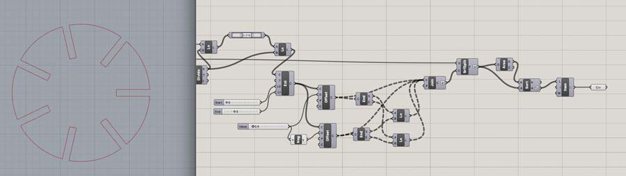
On a new part of the Grasshopper canvas, start with adding the coördinates of a Point and create a Circle with a radius of 10. Then add the Divide component to create 7 evenly distributed points on the circle.
To draw lines in between the center point and the distributed points add a Line component.
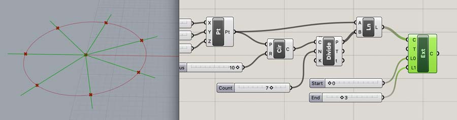
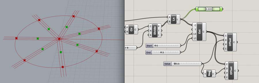
Extend this line with the Extend component.
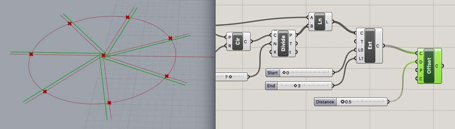
And copy this line at a set distance with Offset.
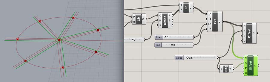
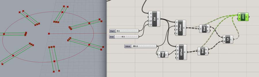
Copy this component to create another line on the other side, add a Negative component to reverse its position.
The next component is Point on Curve. If you change this numeric value your point moves to this position on the curve.
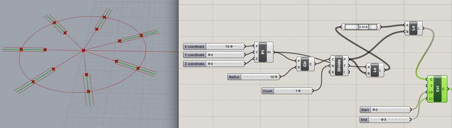
Create another Line in between the Point on Curve and outer points of the circle.
Add an Extend Curve component to make this center line longer.
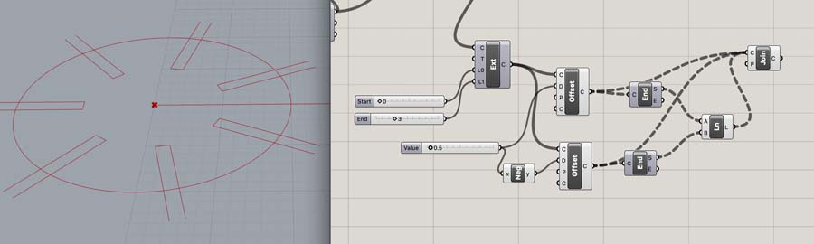
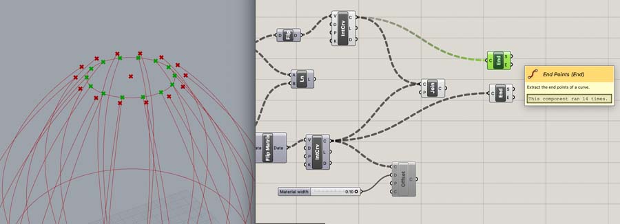
Then add End Points to the two Offsets we previously generated.
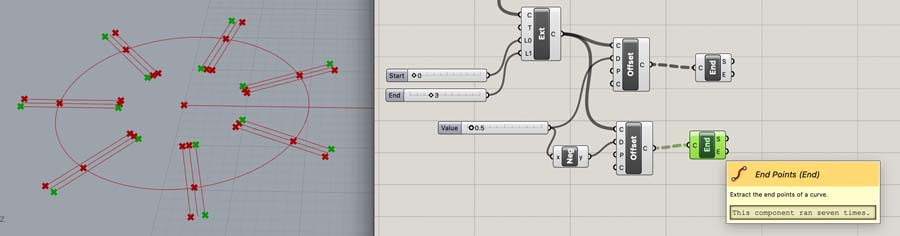
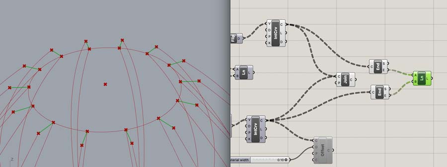
You can now hide these components and add a Line in between them.

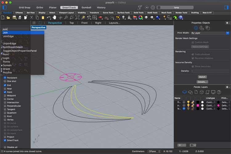
Work with Join to connect this with the two outer lines.
Hide some components to inspect your geometry better.
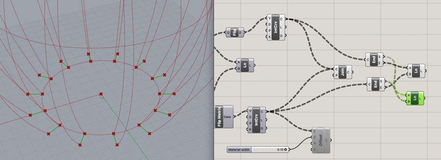
We need to add another Line to the back side of the geometry.
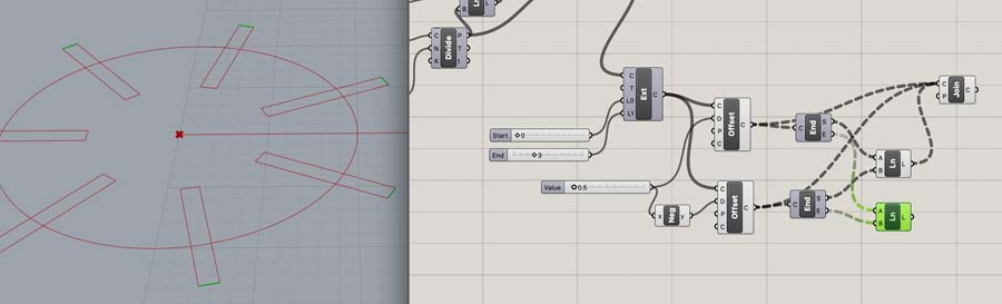
When you also connect this to Join it will create a closed polyline.
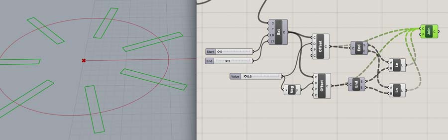
Create two Surface components: from the circle and the rectangles.
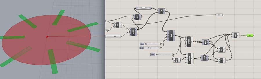
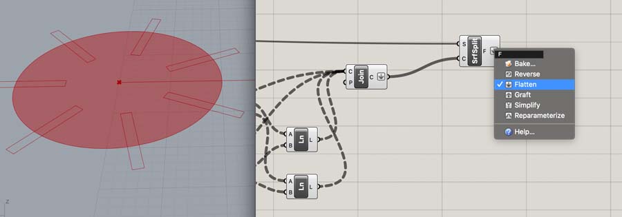
Flatten the Join and Circle components and do the same with a new Surface Split component. The S input value is connected to the Circle.
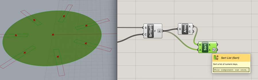
Add the Area and Sort List components.
Make sure to right-click on Sort List’s output value A and select Reverse. Then connect this to a List Item component.
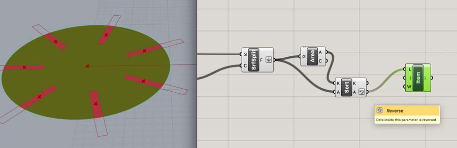
Add a Curve to create the final geometry.
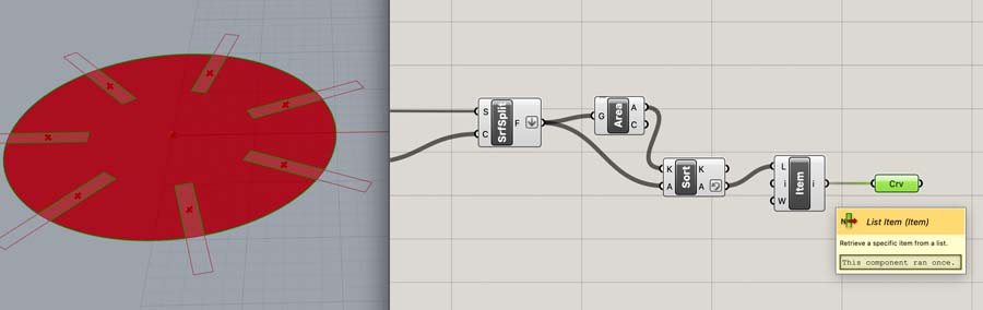
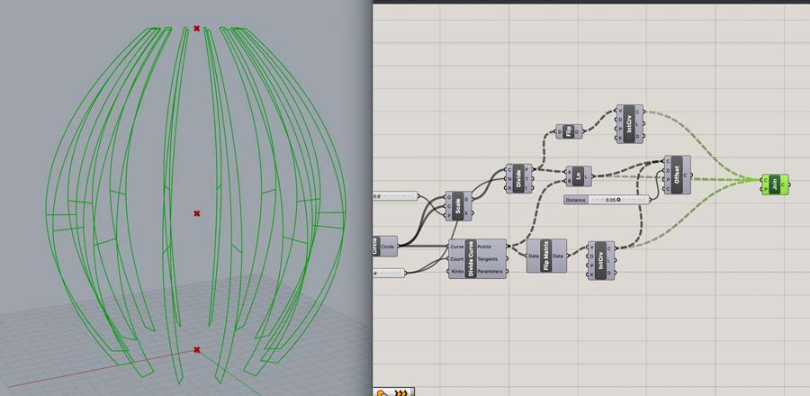
Hide all components except for the Curve to see the result. All values are parametric so if you want to change some dimensions it’s easy. Just change the number sliders.
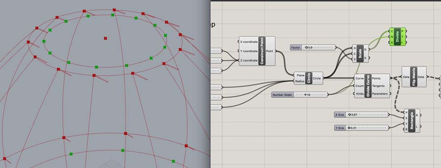
Now create a smaller circle in the center with the Scale component. This will be cut out with the laser.
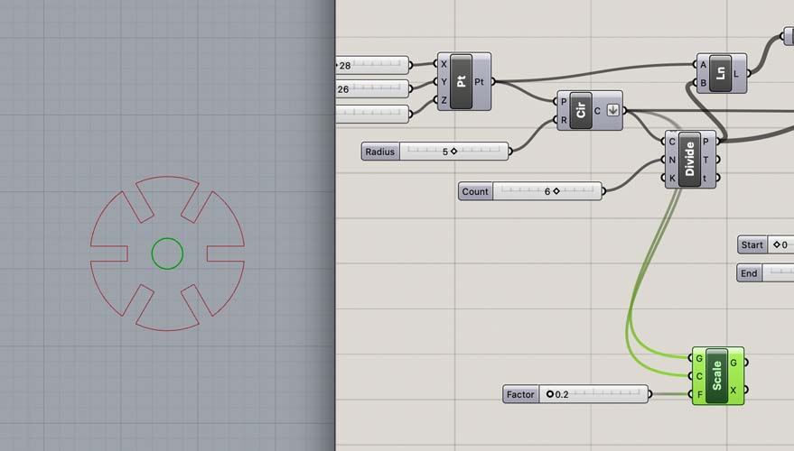
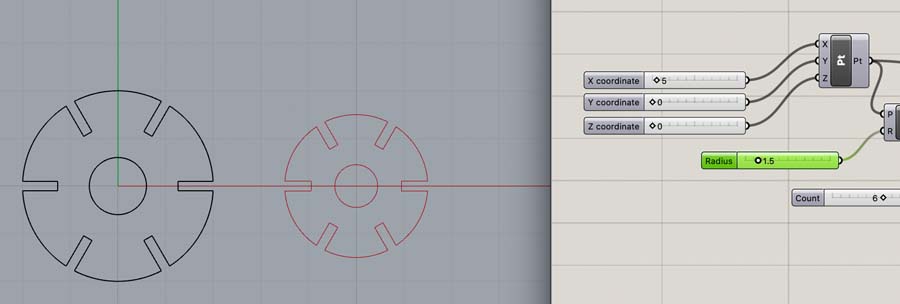
Play with the sliders to create a variety of designs.
If you’re happy, right-click on the final output components and Bake this in Rhino.
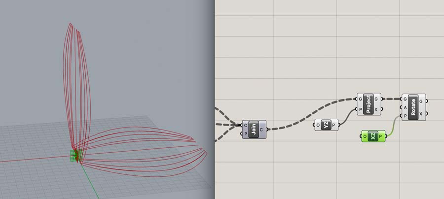
Modeling the ribs
The connector is ready, so we can move on to modeling the ribs. I decided to copy a part of the code used last week and experiment with this. That didn’t give a satisfying result.
So I moved back to the base design and added a Rectangle to Divide Curve. Again, I was not happy with the resulting shape because it didn’t succeed to rotate them around the center point.
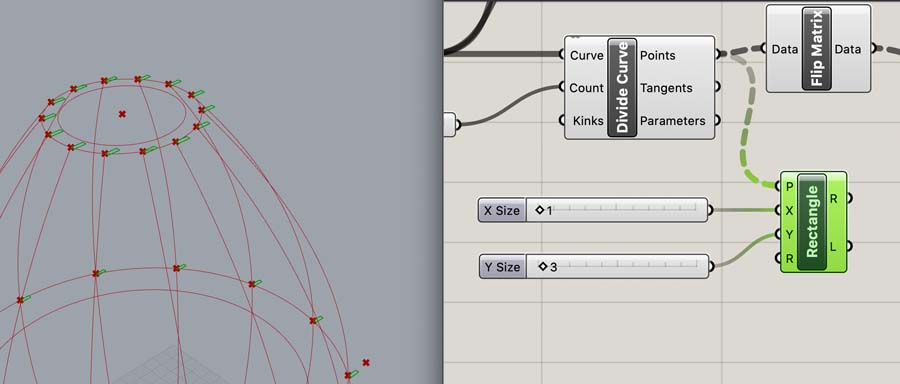
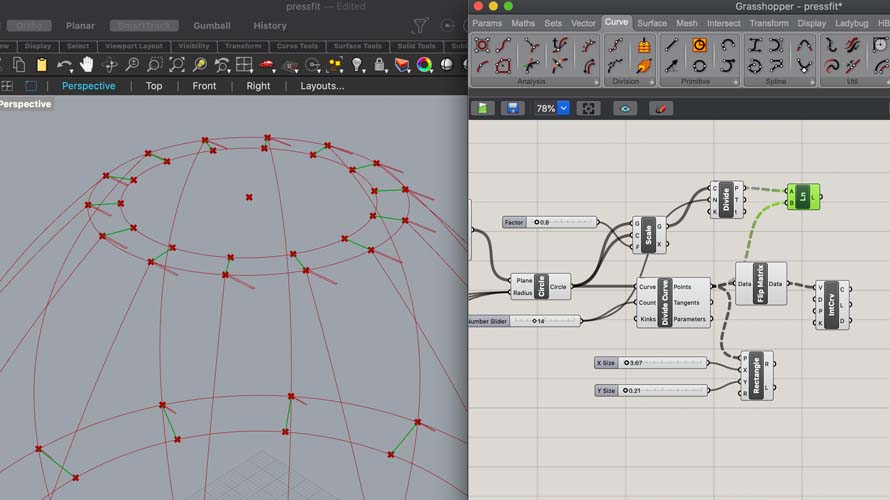
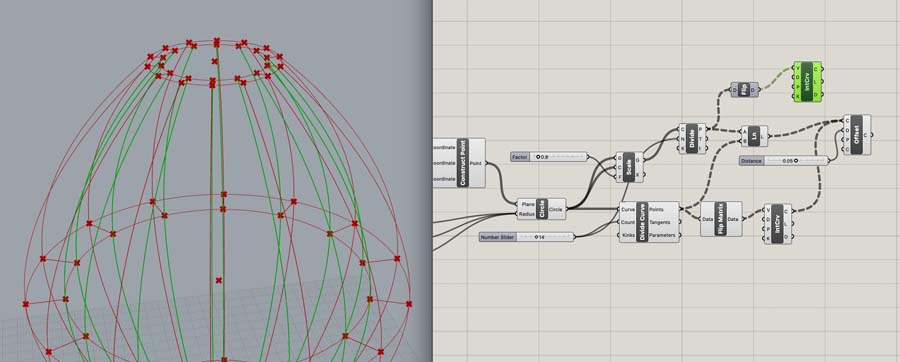
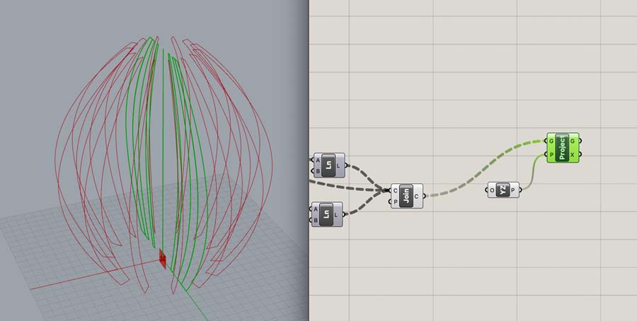
Create a Divide Curve component on the inner Circle. This creates points. Make sure to connect the number of points to the Number Slider of the outer circle.
Now create a Line to connect the points. As you can see this happens on all three plateaus.
Flatten image
Laser cutting
First, an experiment with the width of the connectors. This is an image of Lightburn, the software we use at Waag. When exporting from Rhino to an .ai Illustrator file I had some issues with the dimensions. Make sure to export as an .dxf file.
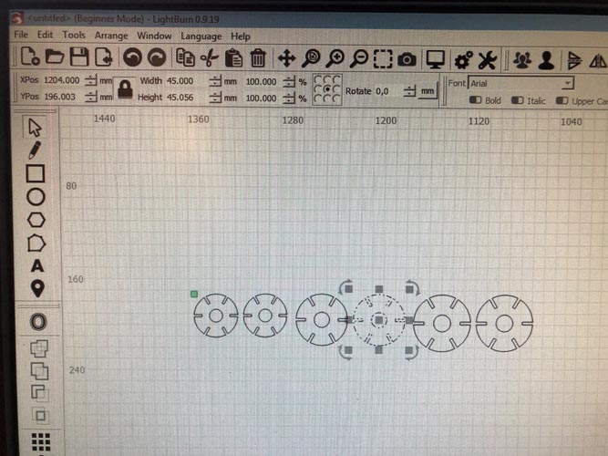
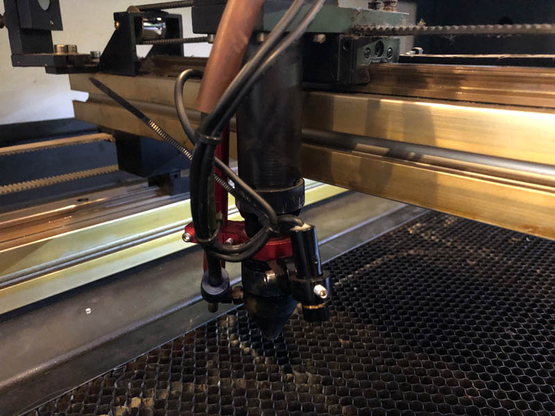
For leveling the Z-axis of the laser cutter, it’s the upper ring. Turn clockwise to open, and counterclockwise to close.
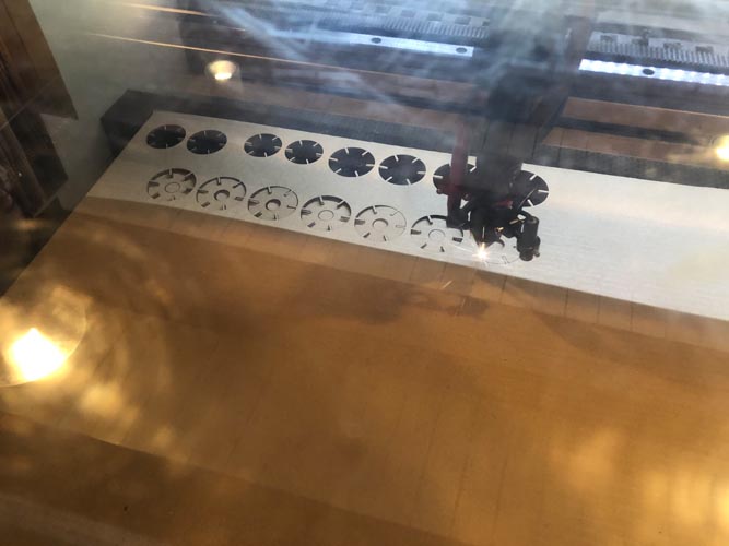
During the laser cutting process.
The diameter of 45 mm gives the best connection.
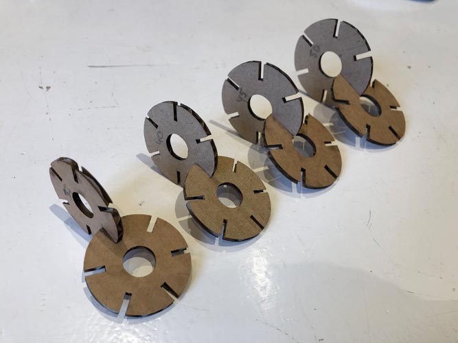
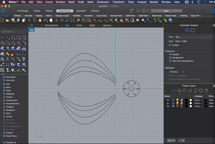
First I made a mistake with exporting the file from Rhino. It was exported as a perspective instead of a top-down view.
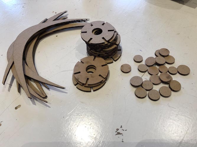
Then, make the ribs.
All parts are ready for assembly.
Assembly
This is the assembly of the first prototype. The material of the ribs was burned, that’s why I lasercut them again with other settings.
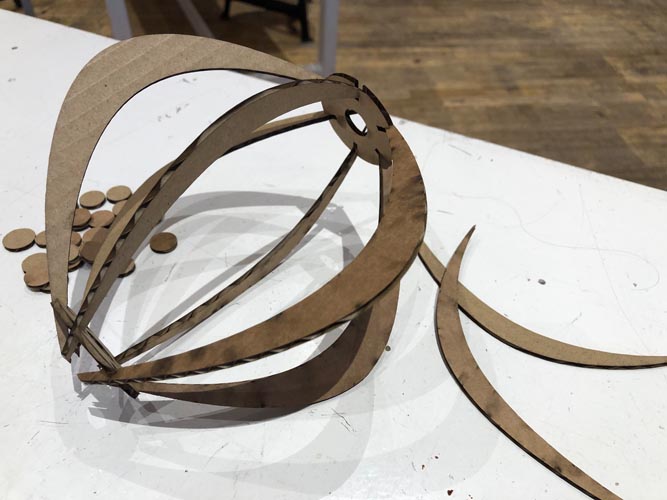
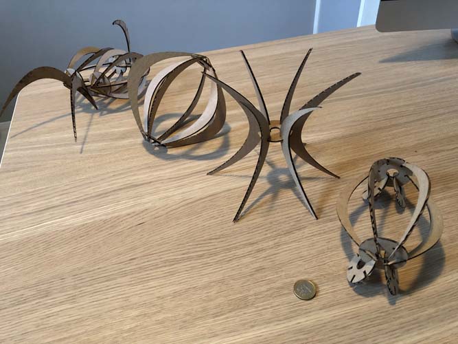
The press-fit kit can be assembled in many ways.
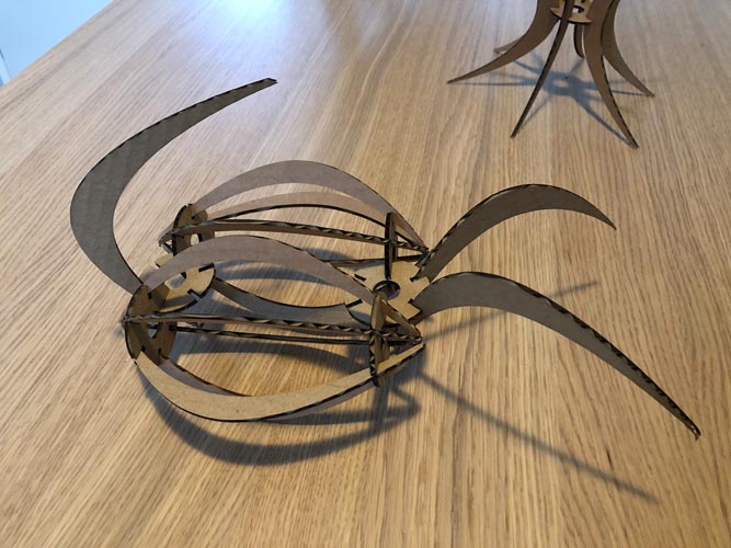
The entire family:
Vinyl cutter
The vinyl cutter at Waag is a Roland Modela:
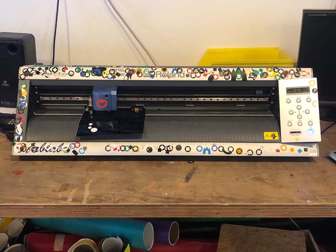
For this assignment, the vinyl cutter is already connected to the server for us. Later when I worked independently, I had to do an additional step for it to work.
On the Linux computer, open terminal to set up the connection. It is important not to click on the file that’s on the desktop next to the mods shortcut, saying ‘start here’. In terminal. type:
cd modsfollowed bybash mods. Now the vinyl cutter makes a connection with mods. In mods you can open the port.
Vinyl cutting copper experiment
The following files were used to cut something on the laser cutter.
Traces
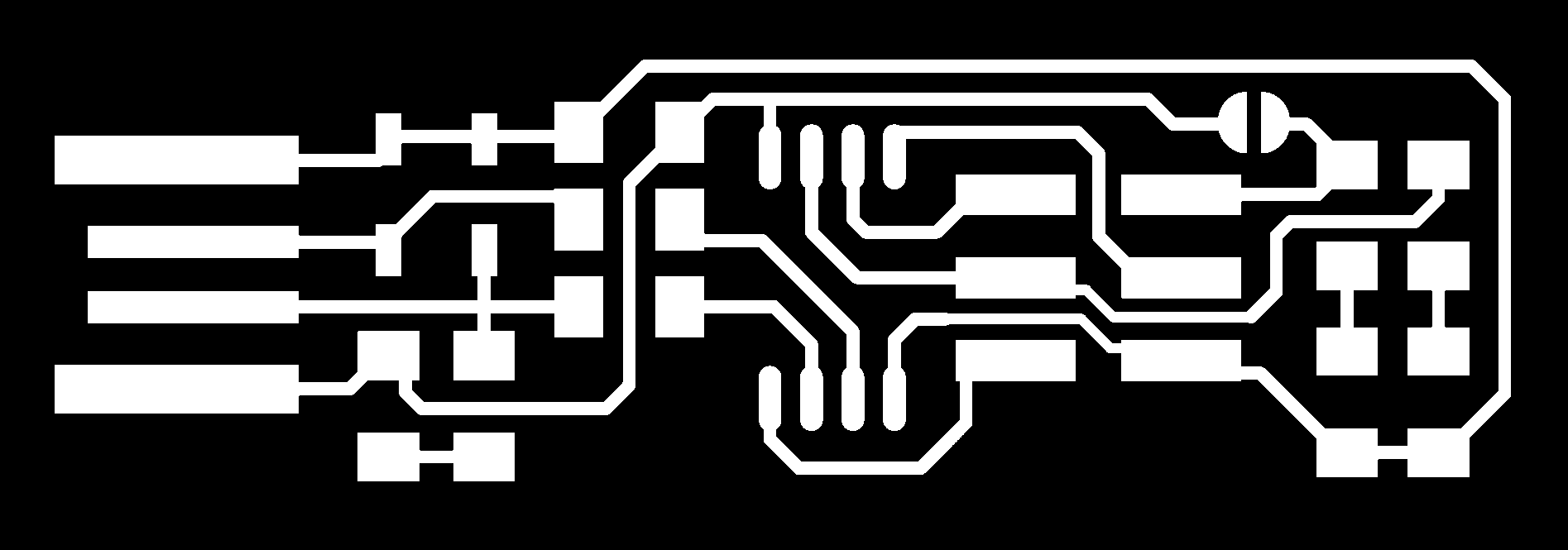
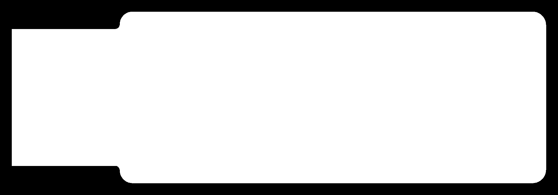
Cut
In mods, prepare the files.
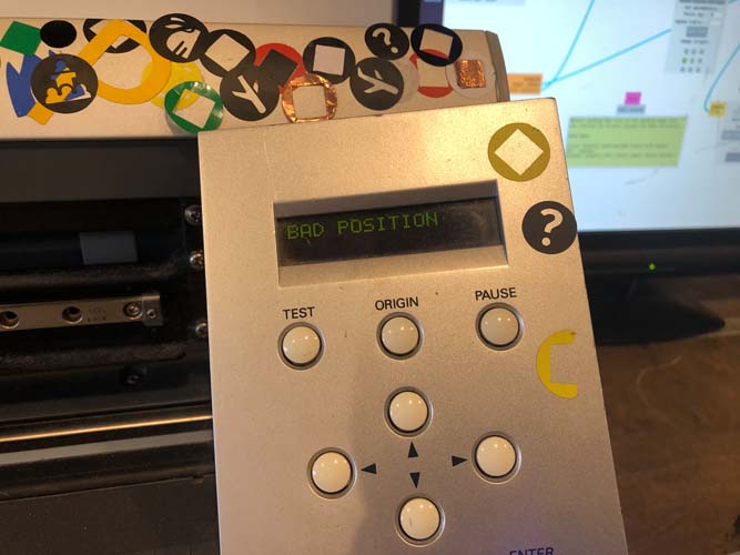
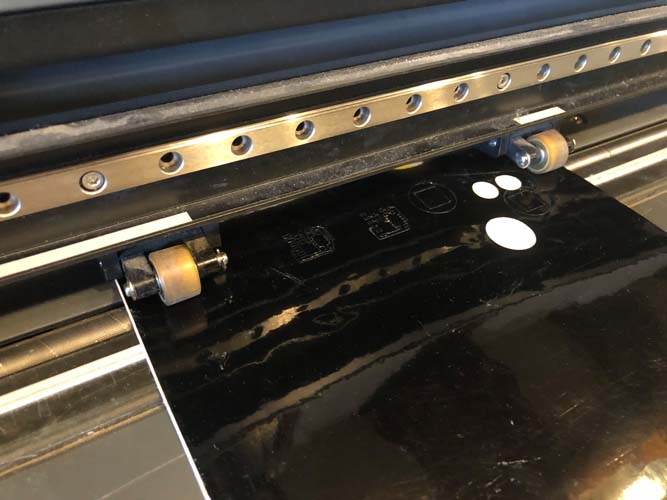
After inserting the vinyl I ran into one error:
Make sure to place the wheels on the areas with the tape.
After the cutting you can weed out the pieces. Some parts went too deep, others were too shallow.
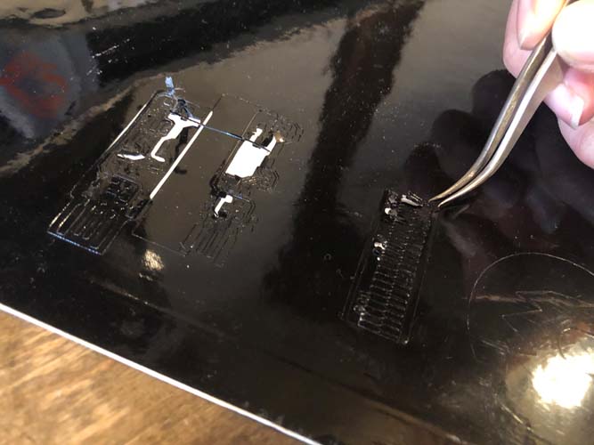
The final results are two stickers: a trace test (actually for the milling machine) and a usb stick. This shows the precision of the vinyl cutter.
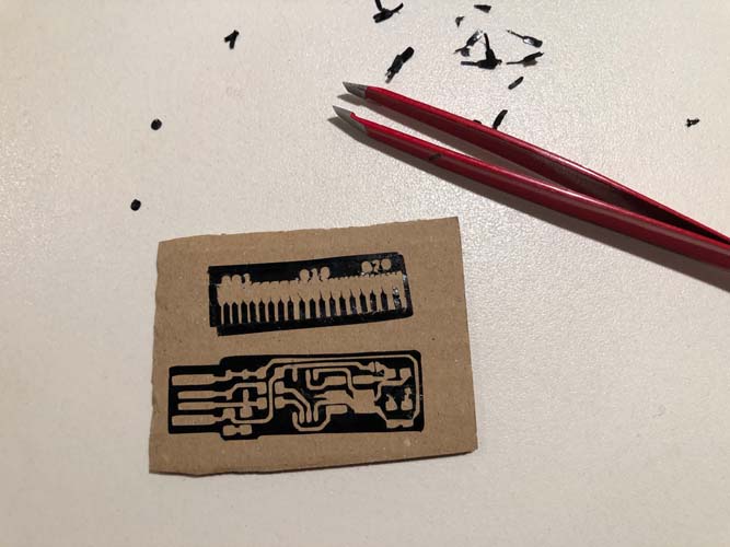
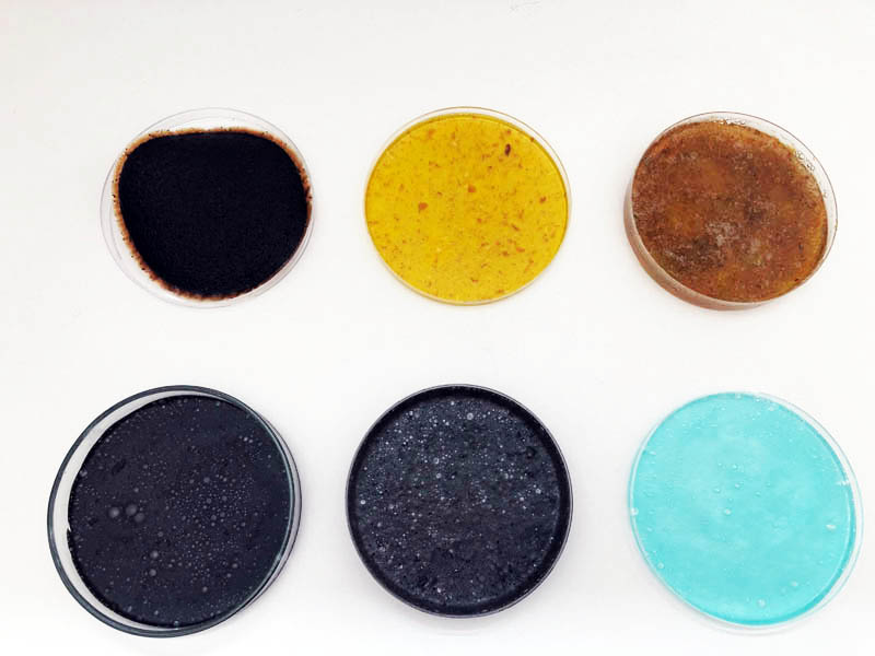
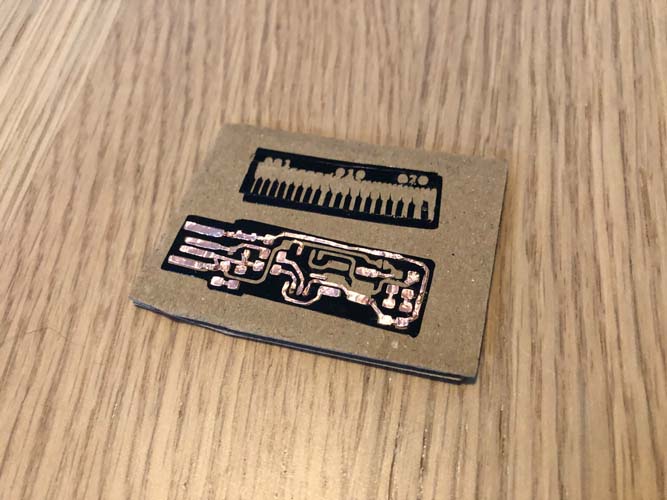
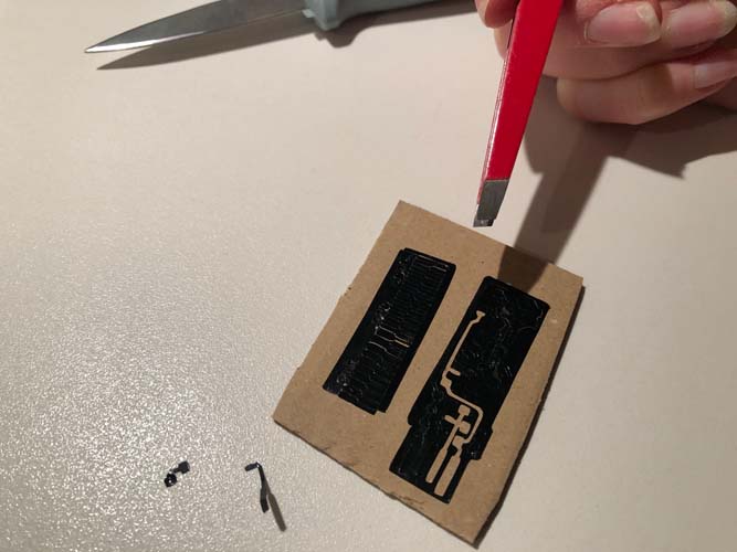
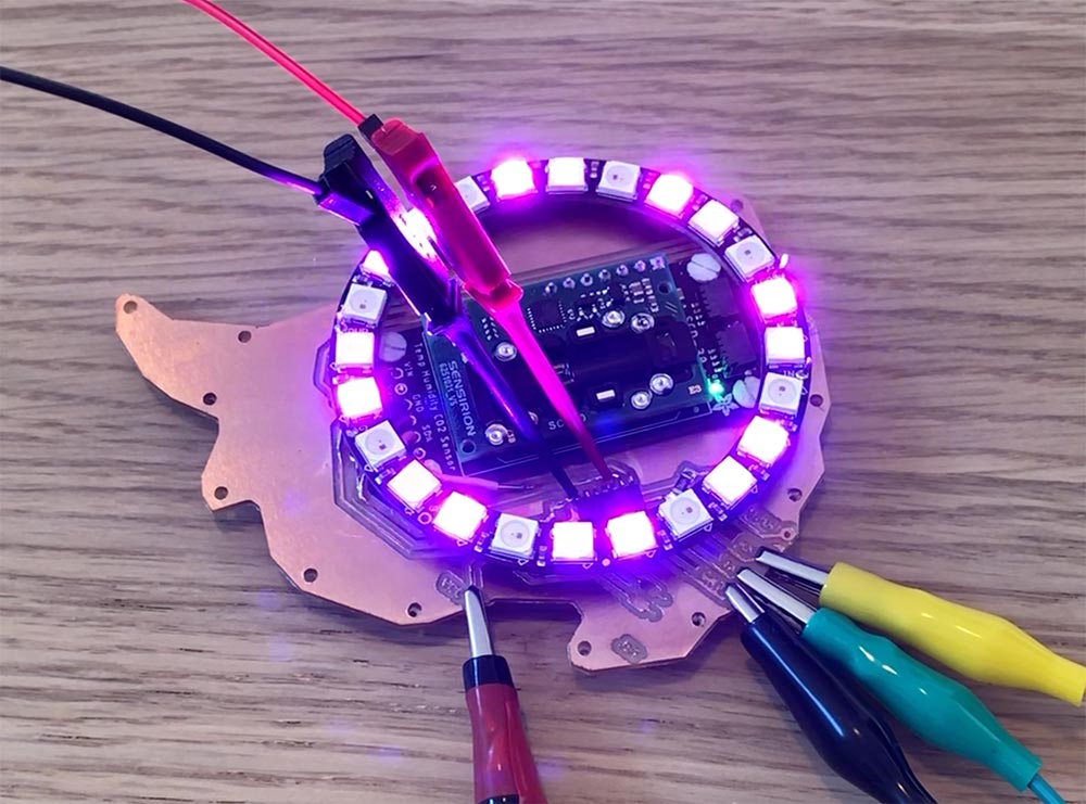
As a test for following weeks about electronics production, I decided to try cutting copper material.
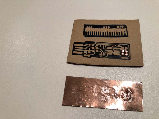
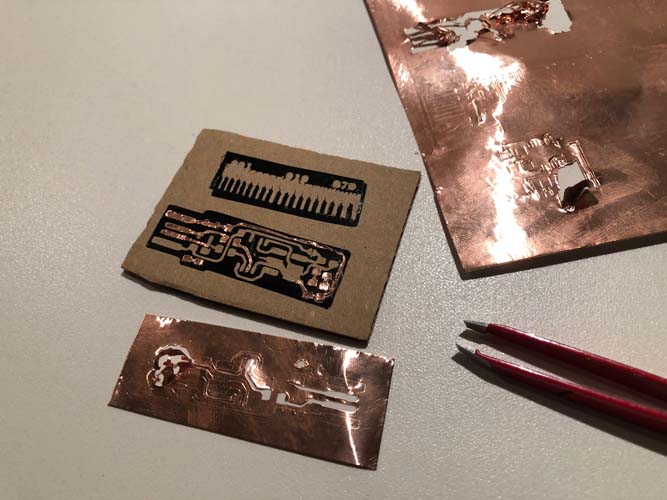
It turned out to be really hard to find the right cut depth. Some parts came out nicely, others were difficult to take out. The result:
Sticker of a skater
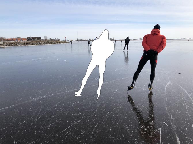
This week, it was cold enough in the Netherlands to skate on lakes and canals. I took this picture:
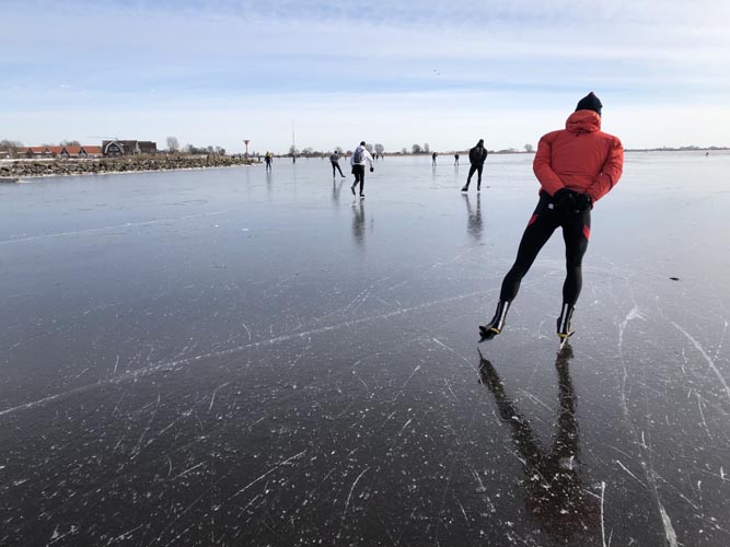
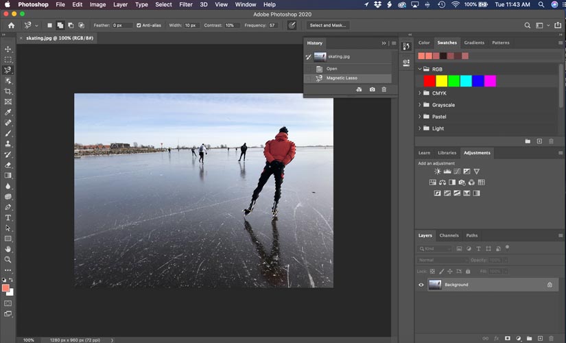
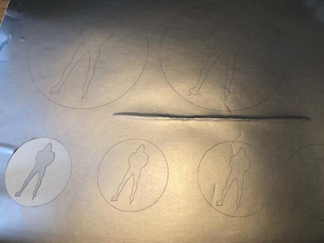
It is really nice to make a sticker out of this, as a memory of the beautiful moments on the ice. In Photoshop, trace the outlines with the Magnetic Lasso.
Copy the shape and paste it in a new layer.
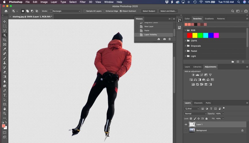
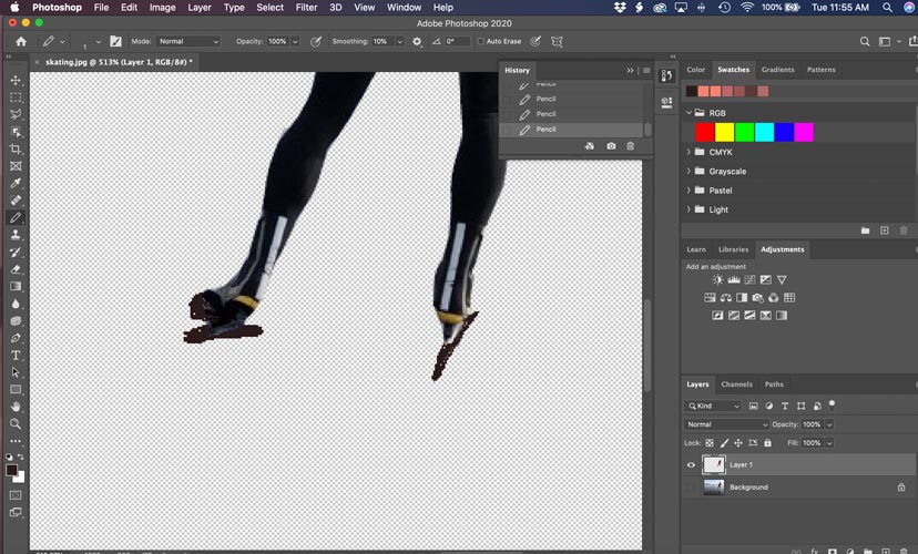
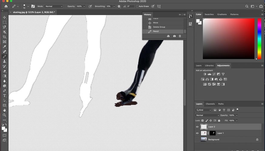
Correct the image manually with the Pencil tool if needed. In this image, I’m correcting the skates. It doesn’t have to be very precise, because the resulting image will only be an outline.
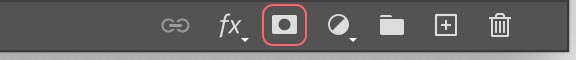
With the Adobe article on Advanced techniques for changing the color of an object, use the Object Selection Tool (W hotkey) to select the item. Next, select ‘Add Layer Mask’.
This creates a black-and-white mask. Click on the mask, while your selection is still active.
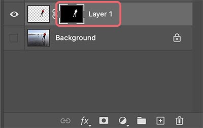
Copy and paste the selection in a new layer. You can move it to see the difference with the original image.
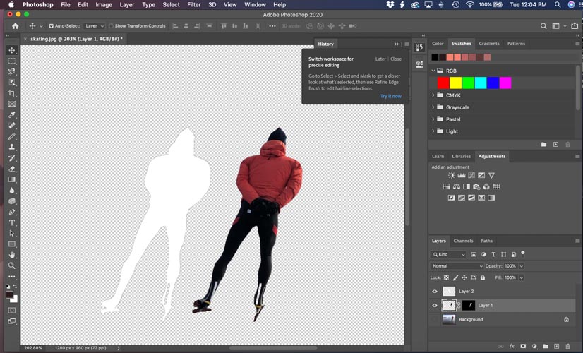
Correct elements with the Pencil tool if needed.
Now we want to add a Stroke to the object. To outline an image in Photoshop, double click on your layer to open the Layer Styles panel. Check the Stroke box and set the stroke type to “Outside”.
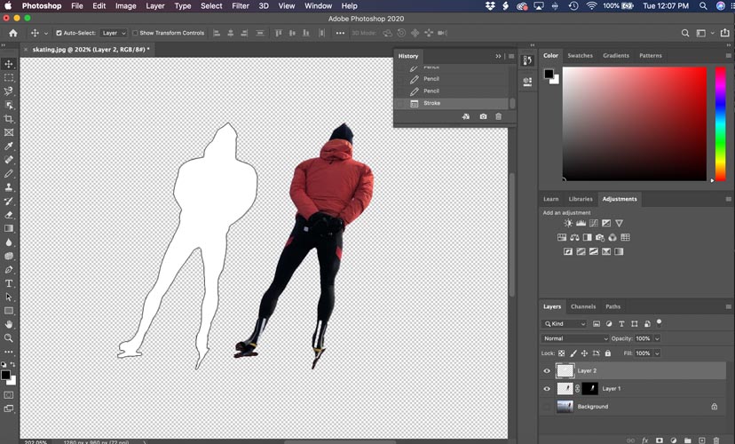
The outline in comparison to the real image.
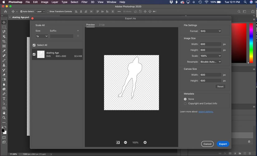
Export the Photoshop file as an SVG file.
Open Illustrator and Click Image Trace.
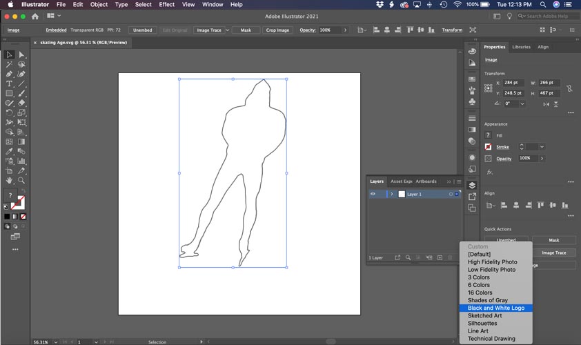
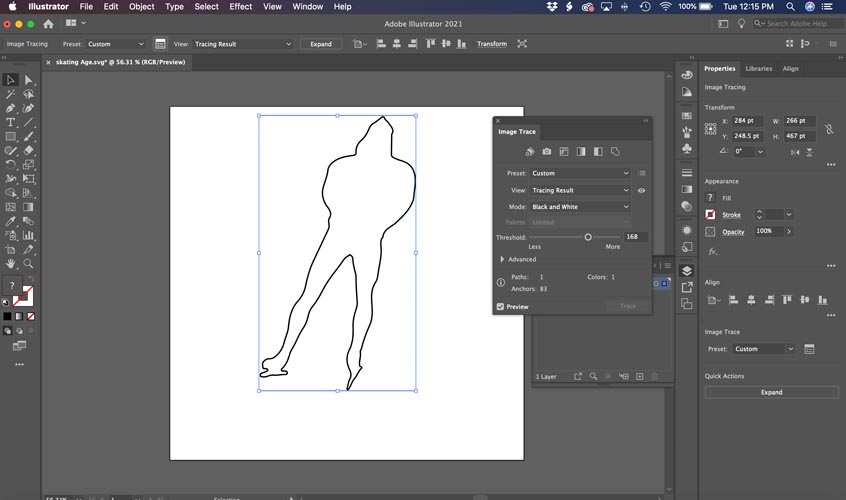
Edit the settings and click on the Calculator icon in the top navigation bar.
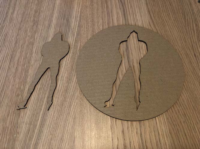
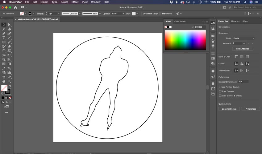
I added a circle to the object to be able to use the positive and negative image.
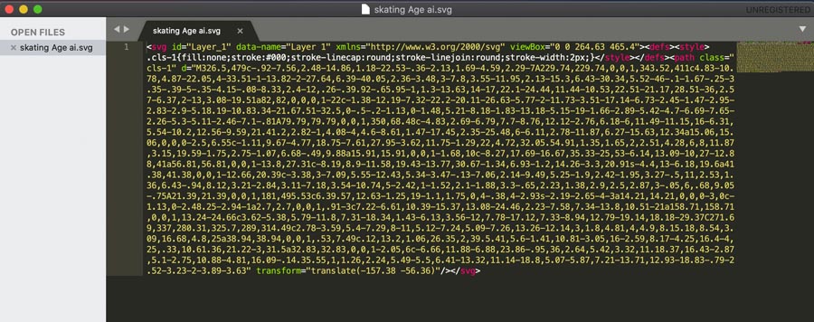
Export to SVG didn’t work in mods. It’s a known problem with the latest Illustrator version. This is how to solve it.
Send to vinyl cutter.
The result!
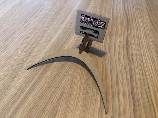
And bonus, a laser cut from the vinyl sticker model:
And a holder for the usb sticker card:
Downloads
Explore more like this
Week 17 Invention, Intellectual Property and Business Models
After acing through the technical assignments of Fab Academy, the last two weeks have a lighter load so we can focus on the final project. But this does not mean...
Week 16 Applications and Implications
Propose a final project masterpiece that integrates the range of units covered, answering: