Week 2 Computer-Aided Design
In this week, we're moving on to 2D and 3D design.
Summary
Digital design is a fundamental skill for fabrication. This week, we explore 2D and 3D design tools. In the past, I have worked with many of them before. However, I’m not an expert in any of them. I would say that my skill set is thinly spread across many tools. Therefore, my objective of this week is to gain deeper experience in a smaller selection of software tools.
Assignments
- Model (raster, vector, 2D, 3D, render, animate, simulate, …) a possible final project, compress your images and videos, and post it on your class page
Learning outcomes
- Evaluate and select 2D and 3D software
- Demonstrate and describe processes used in modelling with 2D and 3D software
Project management
The following steps in spiral development:
| Spiral | Tasks |
|---|---|
| 1 | Download and install all required programs |
| 2 | Try and find a mannequin CAD file for download, otherwise design one |
| 3 | Parametric design of the headband |
| 4 | Parametric design of ear decoration |
| 5 | Image rendering |
| 6 | Exploded view |
| 7 | Gravity Sketch VR design |
| 8 | Render VR image in Rhino |
| 9 | Animation |
| 10 | Simulation |
| 11 | Video editing |
Step 1-6 will be in sequence, and step 7-8 will be parallel to the first six steps. If time allows, I’ll move to animation, simulation and video editing.
2D modeling
In general, there are two types of 2D modeling: vector based and raster based. Both systems differ dramatically.
Raster based
With raster based software, you define the color of every pixel within a rectangular field. Thus, these images will lose quality when you scale them. Some raster based file outputs include jpg, png and gif.
Software:
- Adobe Photoshop
- GIMP
During HTMAA 2018, I used GIMP to create my first gif of a coral.
This is the how-to, adapted and modified from eLearn Hub:
- Open GIMP and then open the first image you want to animate.
- Go to the Layers dialogue box on the right hand side. Name the layer of your first image something distinctive. You now need to create layers with the rest of your images. Each layer is like a ‘page’ for your animation, just like the pages in a hand held animated booklet which you flick through to create animations.
- On the menu at the top of the screen, click, File, then Open As Layers. Select the next image in your animation. You can change the order later if needed. Now click on the new layer and rename if needed.
- Repeat this process with the rest of the images.
- ANIMATION TIME! When your images are all ready go to the menu at the top of the screen, click, Filter then Animation, then Playback. A box should pop up with your animation.
- If the images are too big or too small go back to GIMP and resize using the resize tool.
- To save – file, Export As, rename the object with GIF extension. GIMP then takes you through a series of questions. The answer to the first question is save as animation. In the next box you can change the frame rate to be slower or faster.
Now in the Fab Academy, I’d like to deepen my skills in Photoshop because I will use this in my professional life.
Vector based
With vector based software, you can create images that are scalable. Therefore, useful as input for machines. Typical outputs are svg.
Software:
- Adobe Illustrator
- InkScape
- CorelDraw
In HTMAA 2018, I worked with all of the above. At the time I was positively surprised by the functionality of InkScape. For example, I created the Biosummit logo on a vinyl sticker below. However, I find Illustrator more intuitive and will primarily use this program in Fab Academy. In the section about the final project below, I demonstrate how to work with Illustrator.
3D modeling
In this section I will highlight a couple of 3D modeling software tools.
AutoCAD
AutoCAD is a really old 2D design program from Autodesk. Historically, it is mostly used by engineers. I worked with this during my undergraduate degree in structural engineering. Recently, it has incorporated more 3D functionality.
Fusion360
Fusion 360 is really great for making technical components that can snap into each other. In 2018, I worked with Fusion360 once, in combination with AutoCAD. During CAD week of How to Make (Almost) Anything I made this coffee table.
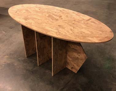
This is the design:
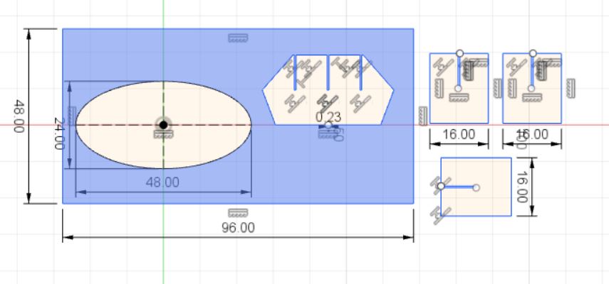
- Download the .dxf file
FreeCAD
During the fist six weeks of How To Make (Almost) Anything I used FreeCAD to design a parametric construction kit. FreeCAD worked relatively well and I appreciated the possibility to set conditions. However, the program had some difficulties with drawing lines under unusual angles and deleting lines in a quick manner. For the sake of time I decided to export the file to AutoCAD to draw the lines manually. The command line in AutoCAD is extremely useful and I missed that functionality in FreeCAD.
Rhino and Grasshopper
For this assignment, I will work with Rhino and the Grasshopper plugin. Rhinocerous (Rhino, in short) is a 3D modeling program, mostly used by architects. It has a plugin called Grasshopper that can create parametric designs. I have limited experience with these programs and would like to develop my skills.
A selection of supported file formats in Rhino are:
- .3dm
- .dwg
- .swg
- .obj
- .step/.stp
- .stl
We will need this information when we convert our designs to machine-ready outputs.
Freeform sketching
Finally, I’d like to conclude this section with a really cool new feature. With modern technological advances, it is now possible for the broader public to design without a mouse and/or keyboard.
Apple pencil
For example, the Apple Pencil allows for 2D and 3D design on an iPad. There are apps for Adobe Illustrator and Indesign. I’d like to explore them during Fab Academy.
Siemens NX
During class, Neil showed a video of Siemens NX. This is an intuitive tool where SpaceX designers work in. Neil mentions that it is only useful to learn this if you work in large teams. I’m intrigued by this.
Virtual Reality
For this assignment, I will be drawing in Gravity Sketch. This is a new Virtual Reality program for CAD design. I believe the future of design will be a mixture of traditional and hypermodern tools. We will be liberated from the limitations of a keyboard and mouse.
Model a possible final project
My idea for a final project is described in the Principles and Practices post from previous week. In this section, I’ve designed a parametric ‘oorijzer’.
Mannequin
To draw the wearable, I need a mannequin. Preferably a female. There are many free CAD objects out there, for example on Grabcad. On Turbosquid, I found this dude:
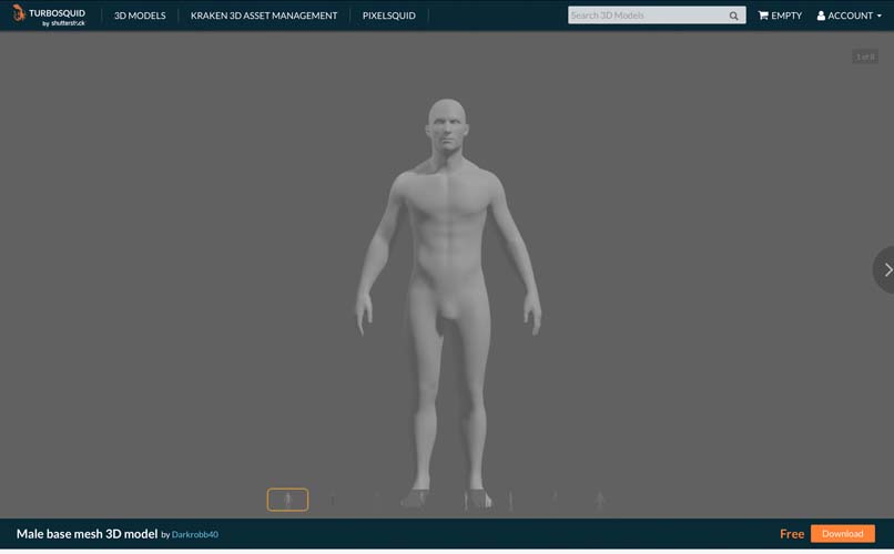
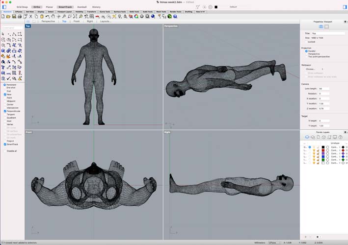
I downloaded the step file and uploaded this in Rhino.
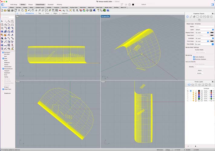
There is a lot of crap in this file! Let’s find our guy and delete the rest.
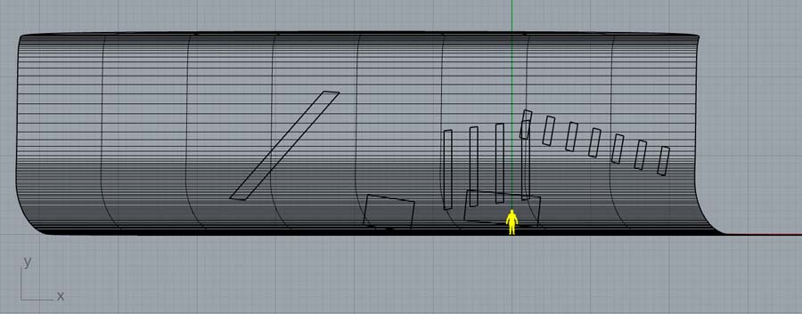
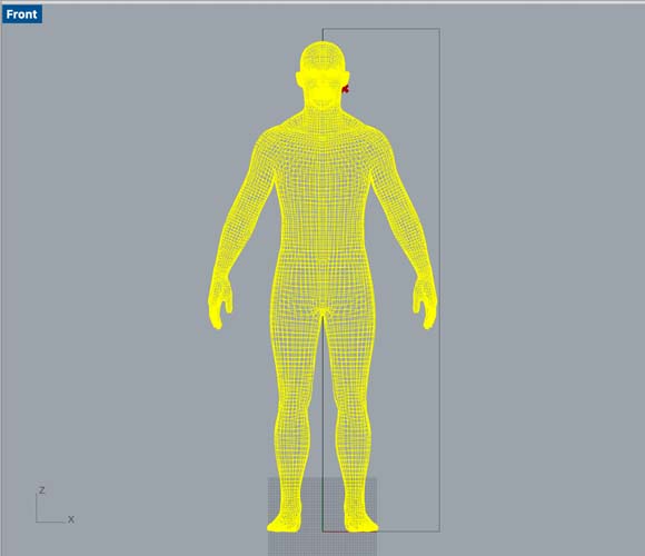
If we zoom in with the zoom extents all command, we can find him.
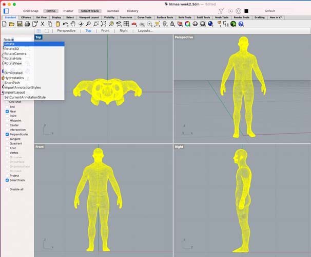
Next, use the command rotate to place the man in the right direction.
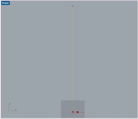
Another good practice: first check the scale and size of your object. Turns out, this guy is tiny.
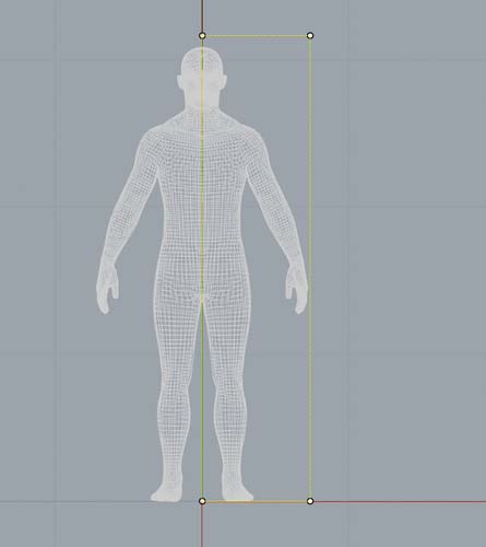
We draw a line with a length of 180 cm. And resize the man to the end of that line with the scale command.
Sides of the oorijzer
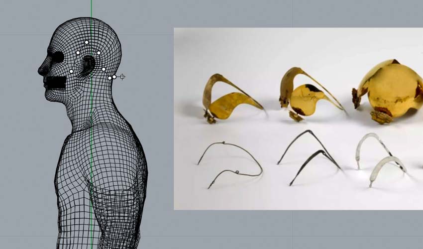
Now that we’ve set our man in the right position on the canvas, we can start with parametric design. First, we add a reference image of the ‘oorijzers’ with the help of this tutorial.
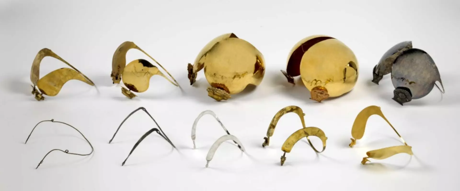
Image courtesy of the Fries Museum
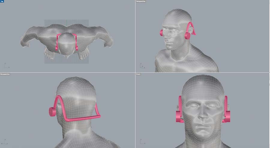
With a polyline, draw the oorijzer in Rhino.
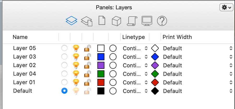
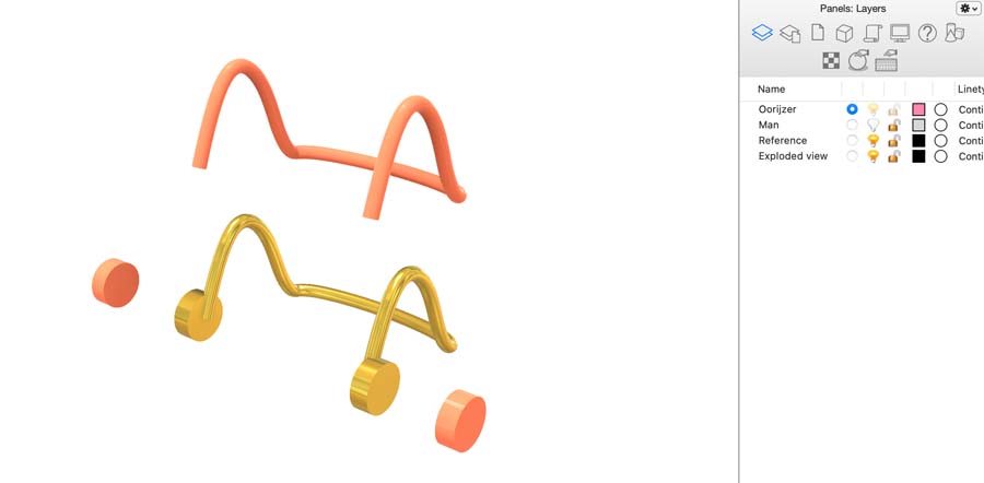
Good practice: work with layers. This is what the standard layers panel looks like:
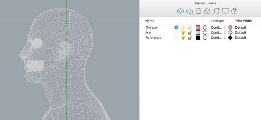
I created three new layers, moved the objects and deleted the old layers.
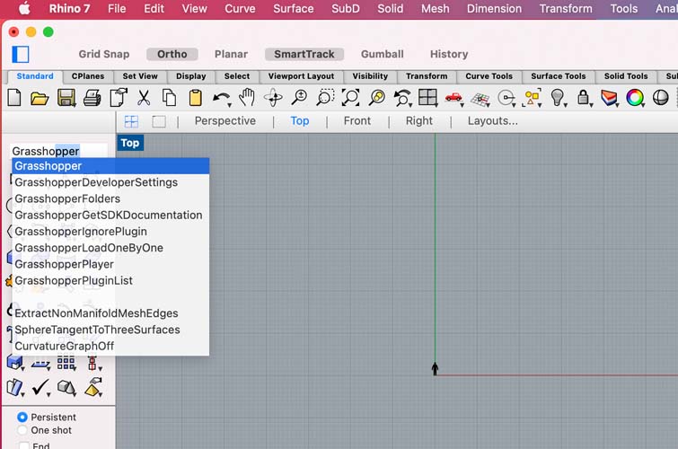
Now we can start with parametric design. We open Grasshopper by typing this in the command line.
For the parametric oorijzer, I used this parametric chair tutorial as a starting point. Because I have very little experience with Grasshopper, it’s great that those resources exist.
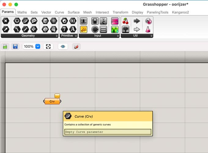
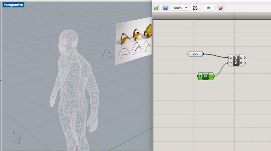
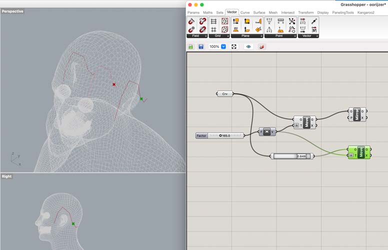
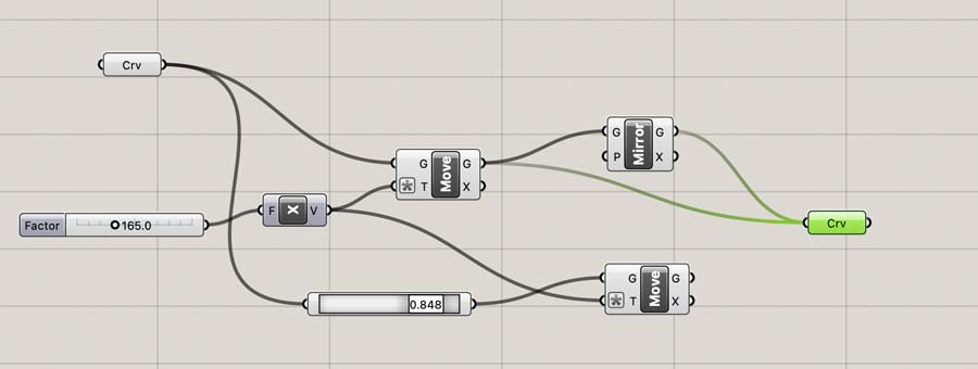
We start with the polyline curve of the oorijzer. In Grasshopper, right click on the curve to connect it to the one in the Rhino canvas.
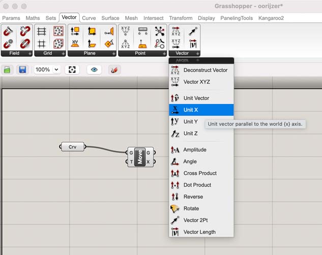
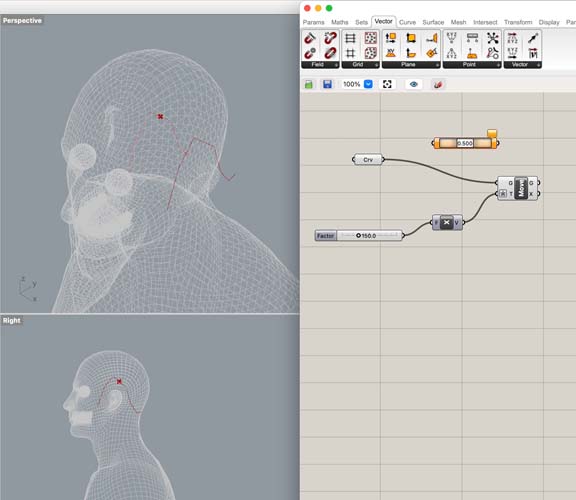
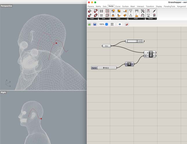
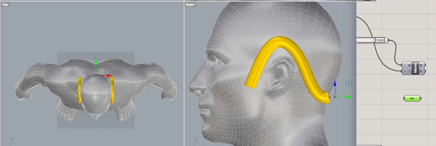
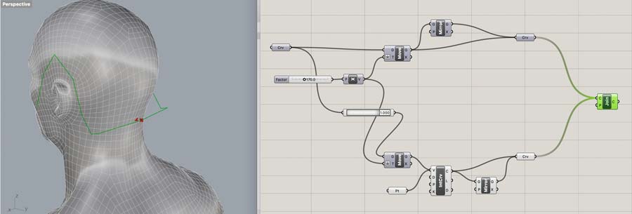
We want to create a line on both sides of the head. Therefore, add a unit X vector to indicate the direction of the move.
This will place the second line too far away. We want to parametricize this.
Therefore, we create a number slider by double clicking the canvas. Type a number to set the total distance (in mm).
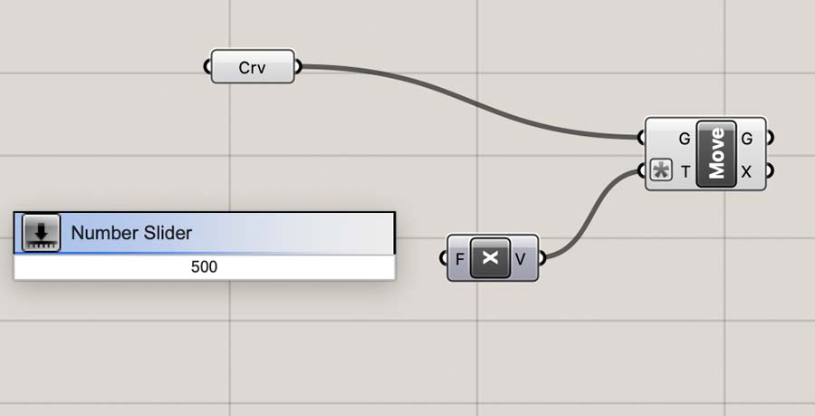
You can change this number by right clicking the slider, and hit edit.
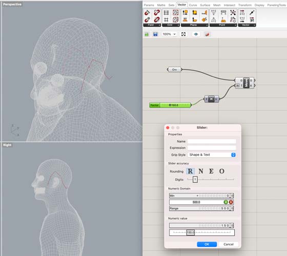
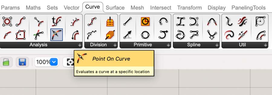
Next, hit the command point on curve to create a point that travels along the curve. We will need this later for creating the decorative item on the oorijzer.
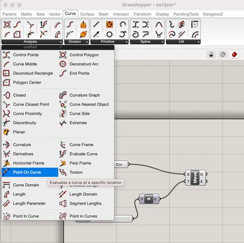
The first parametric element!
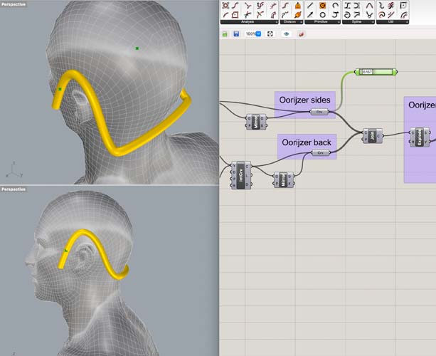
Add mirror to duplicate the polyline. Because of the symmetry of this object, we only need to draw half of it.
An experimentation that didn’t quite work.
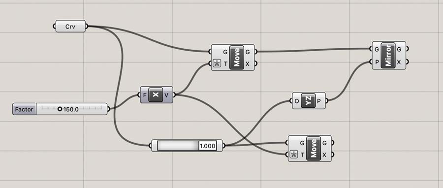
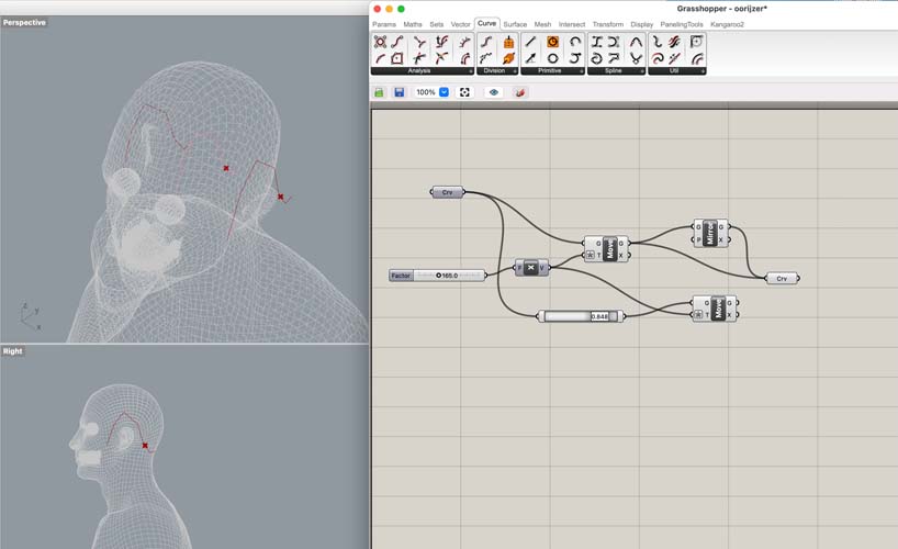
Another iteration with visual feedback. This operation creates the two desired polysurfaces.
We merge them into one curve.
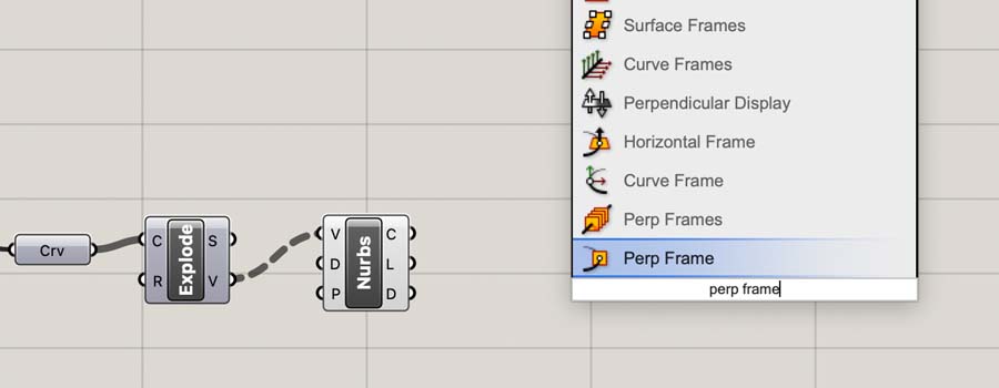
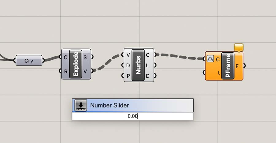
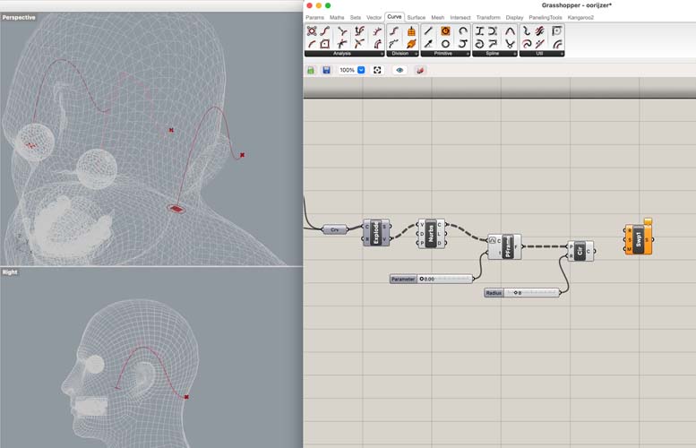
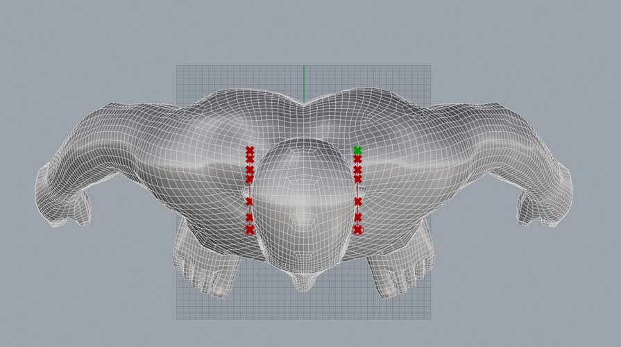
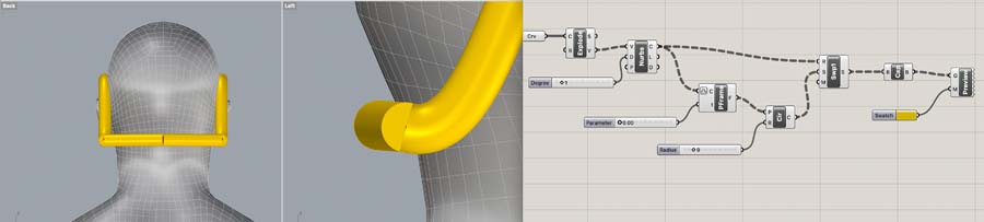
We Explode the curve to show the points, and add Nurbs Curve to make a smooth line. Later in Rhino the points can be relocated to change its shape, if desired.
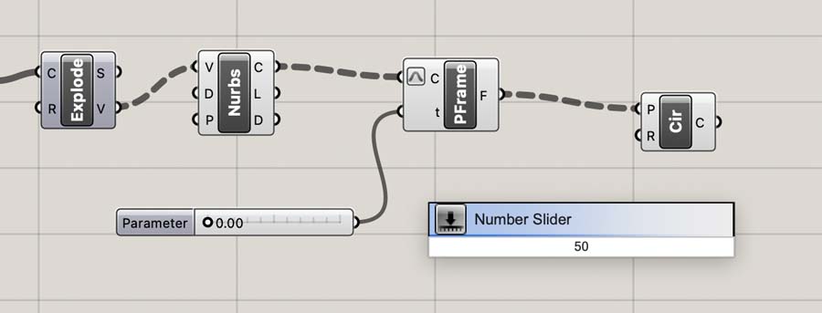
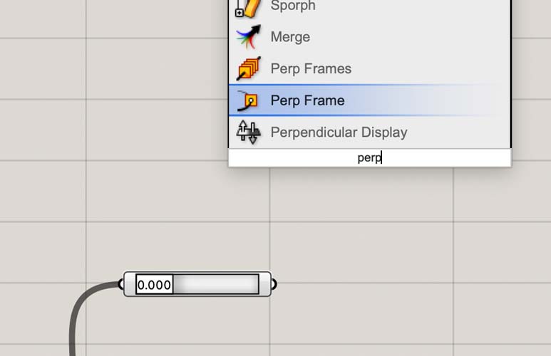
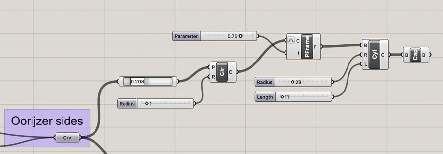
On this curve, create a perpendicular frame with Perp Frame.
Right click and ‘Reparameterize’ it.
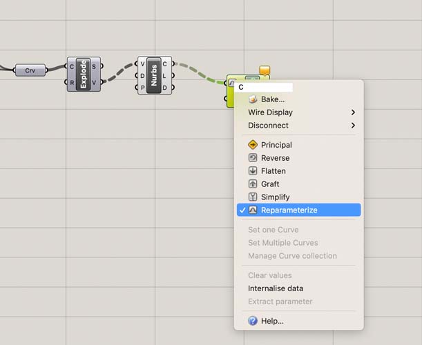
Add a Number Slider to indicate its position relative to the curve.
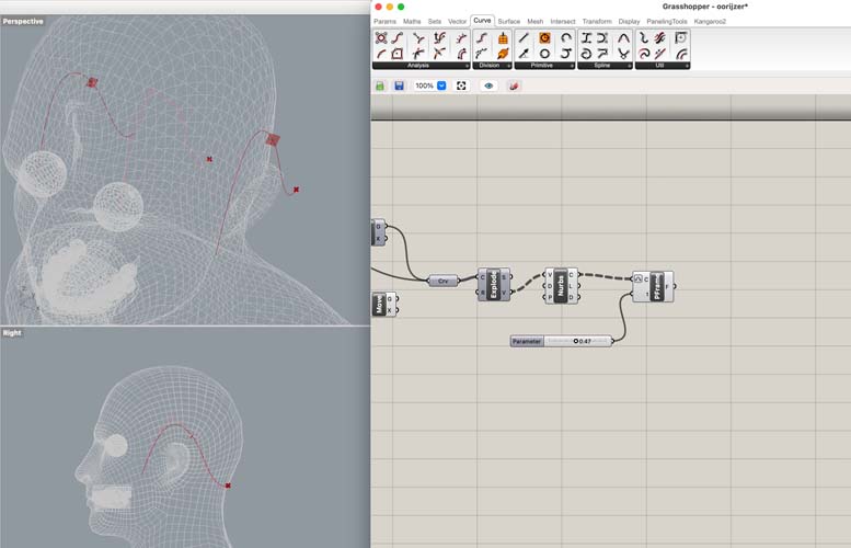
This is the movement we’ve created:
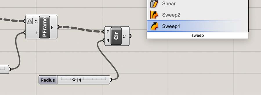
Now we add a Circle that will sweep along the curve in a later step.
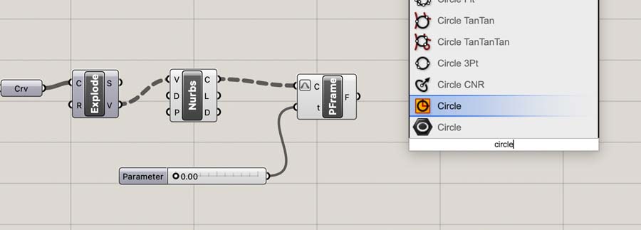
It asks for a radius which we will provide by adding a Number Slider.
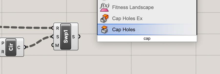
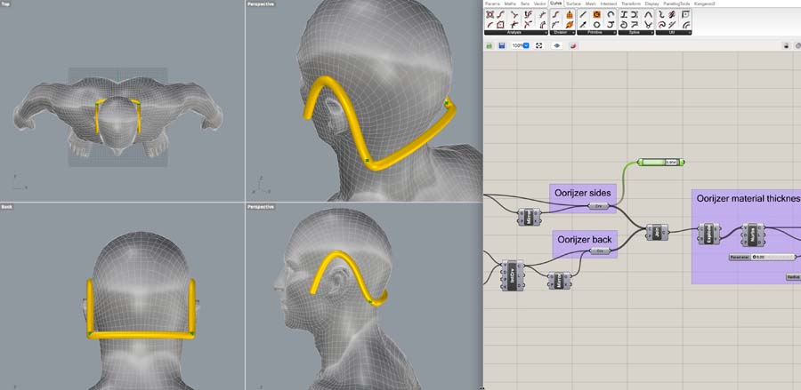
Then the Sweep to create the material thickness of the curve.
Connecting the dots:
Add Cap Holes to close the ends.
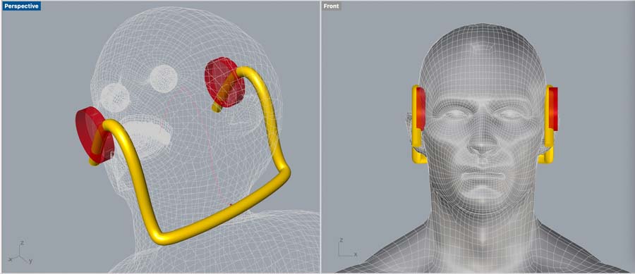
Next, we add Custom Preview to visualize what we’ve done. With Color Swatch you can add a color.
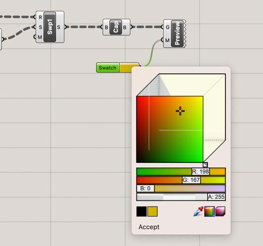
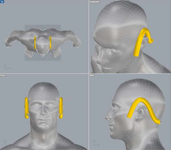
This is the result! Woahh can’t believe it.
Back of the oorijzer
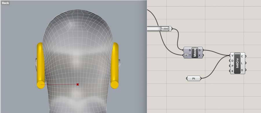
Now we need to connect the two sides with a curve along the back. This TU Delft wiki provides a tutorial for creating curves from points or other objects. We start with the point on one of the sides.
Next, we create a point on the center of the head.
And Interpolate it.
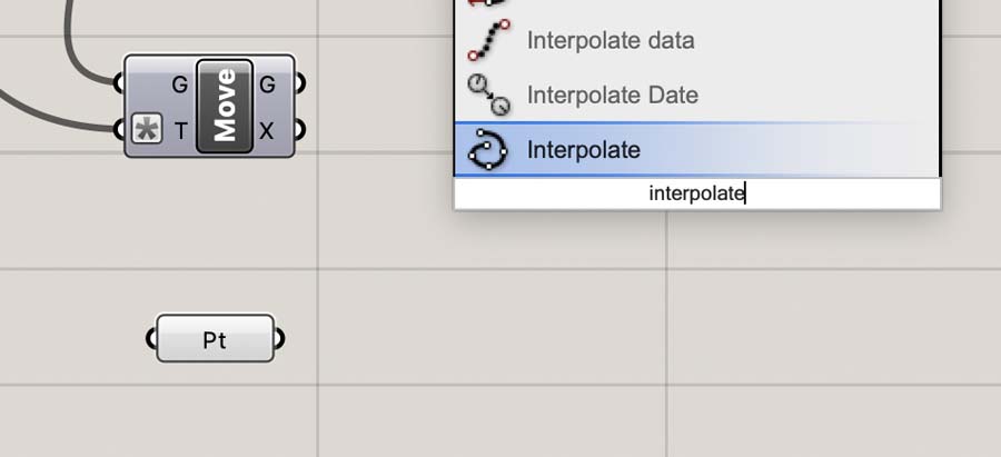
This generates a line in between the two points.
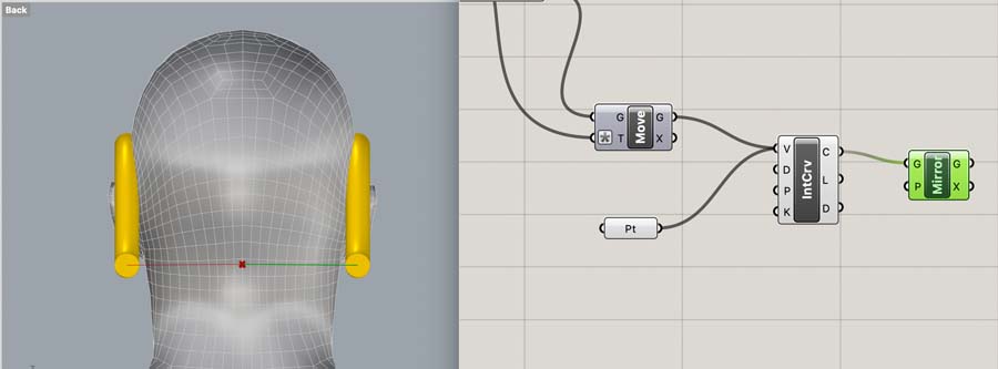
We Mirror this, just as we’ve done before. It looks like this works.
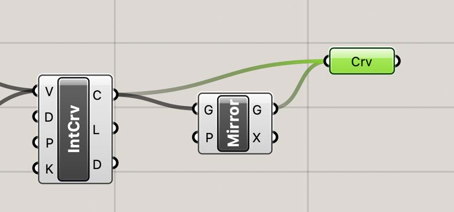
Then we combine the two curves in Curve.
Now we need to add the material color and thickness. We can try to copy and paste the code we’ve created earlier. It does create a result. Though I’m not satisfied with the chunky connections.
Also, there is a duplicate in the code, which is ugly.
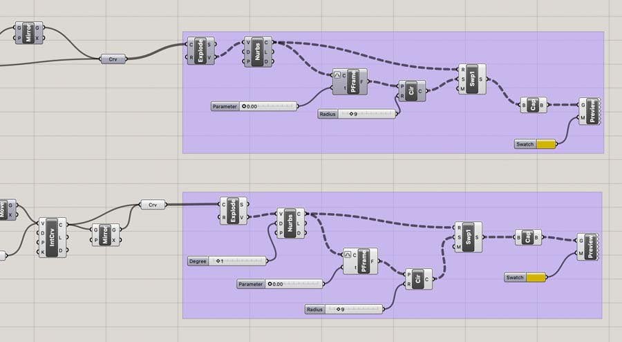
The join curves command creates a singular line.
Next, we paste the same code. This creates a beautiful fluid output for the back side of the oorijzer.
Optional: reshape and mold the points in Rhino. That’s too much detail, so I will leave that for now.
Decorative oorijzer part
Now we want to add decorations to the sides of the oorijzer. I think point on curve could be the way to go.
This is exactly what we want!
Use the slider to move the dot back and forth:
Next, we want to create a circle perpendicular to the curve. We’re going to recycle the Perp Frame command.
Next, we add a circle to visualize the result.
Unfortunately, the extrusion will go into one direction. This is not what we want.
Because the source code doesn’t allow for a split, we’re trying a different route.
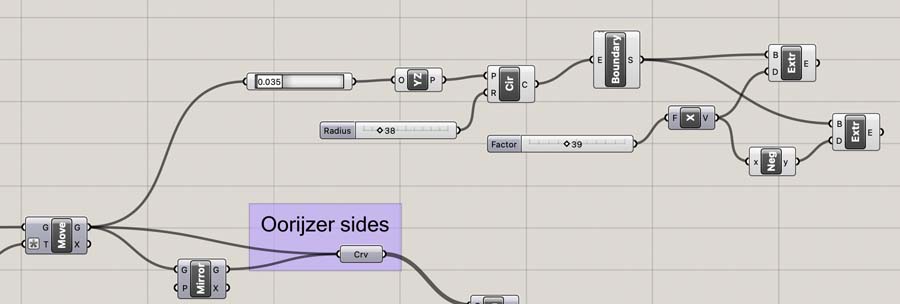
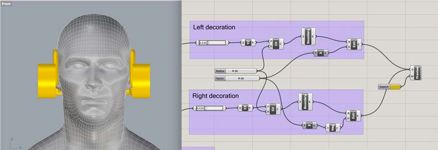
Next try, I started the process from one side. I will try to create the decoration on one side, mirror and duplicate this to the other side, and combine the code later if possible.
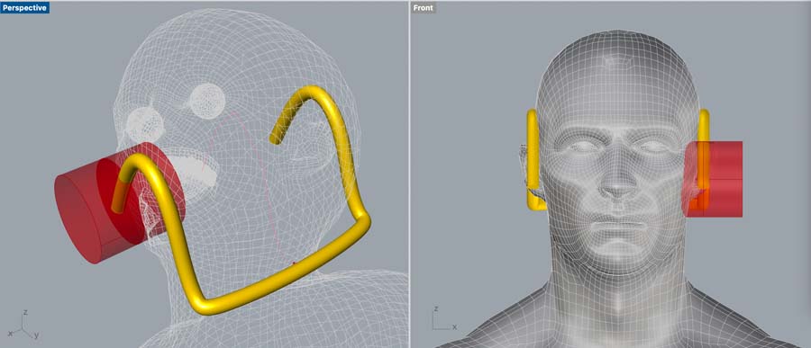
With this Youtube tutorial I created the extrusion in X direction. unit X is needed to specify the direction of the extrusion. This means, that the other one needs to be -X.
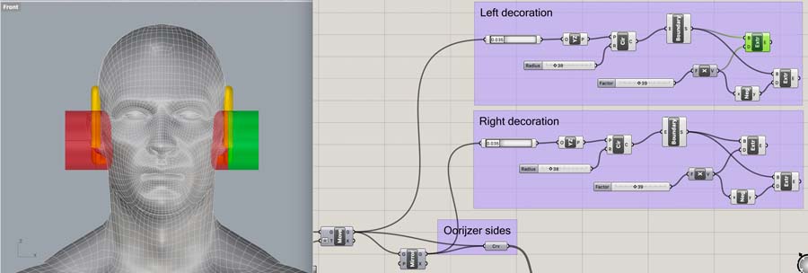
This creates an ear iron on both sides.
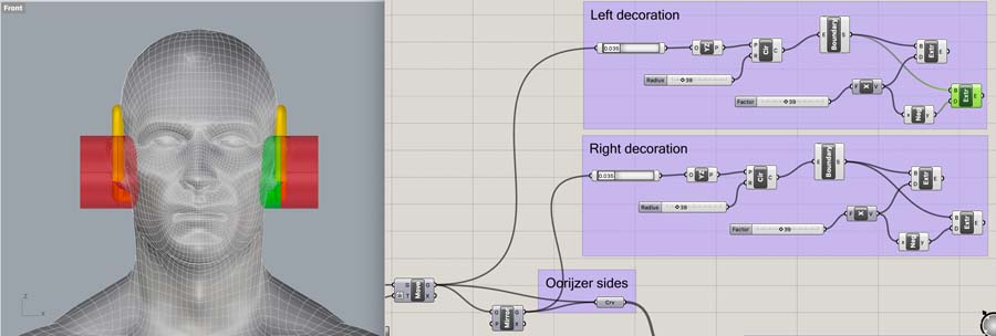
Now, we can delete the inner parts.
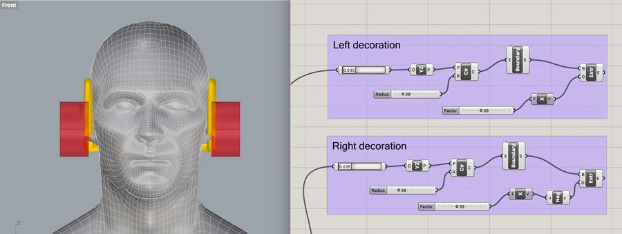
And it’s done. However, let’s see if we can simplify the code by recycling the sliders.
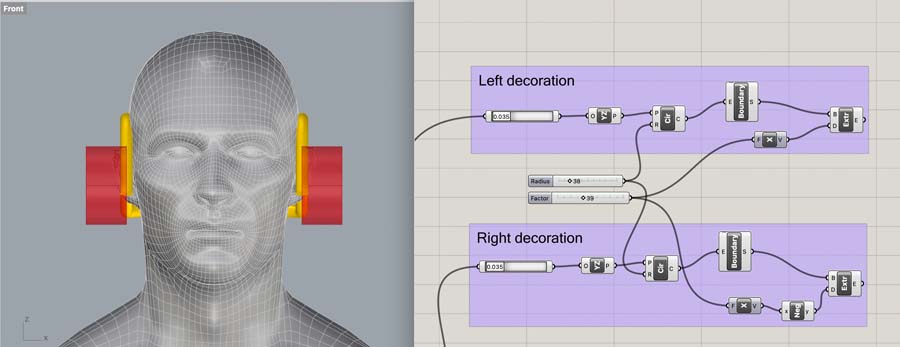
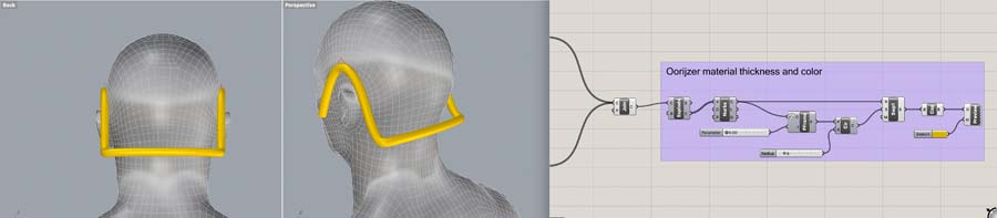
And add the color and material.
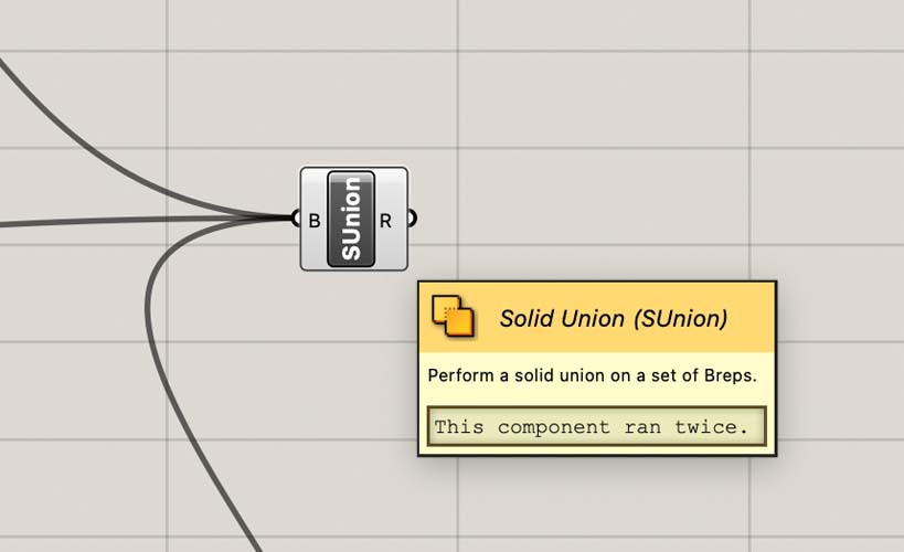
Then we make a Solid Union.
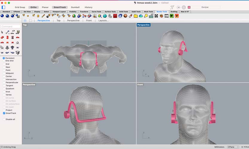
And right click to Bake it in Rhino.
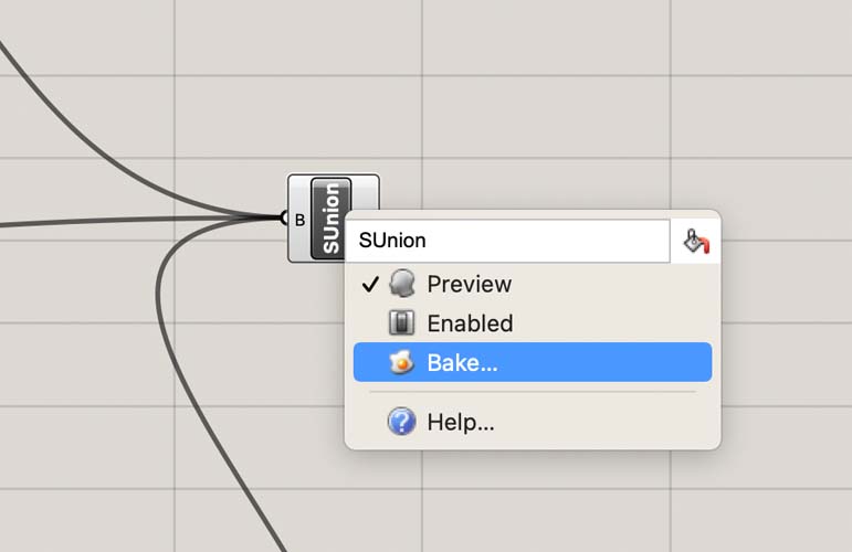
Done!
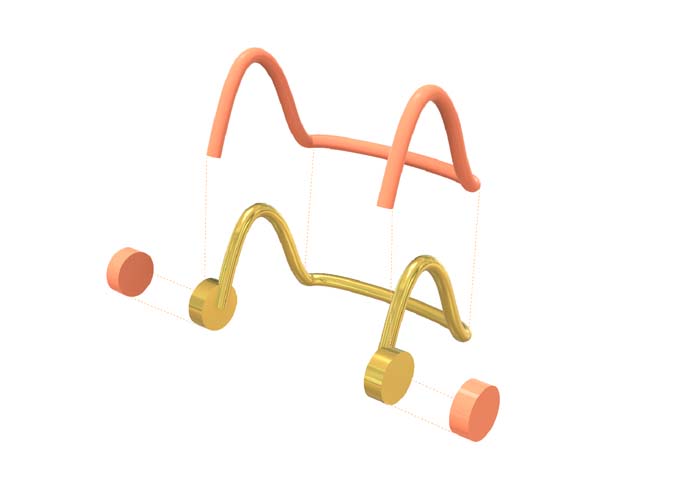
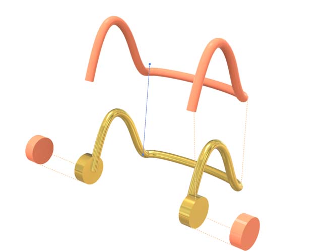
Exploded view
Here is an exploded view of the oorijzer:
This Youtube tutorial provides an overview of how to create an exploded view in Rhino. I was not quite content with this because with this method you can easily destroy your model. Someone on the McNeel forum offers valuable advice:
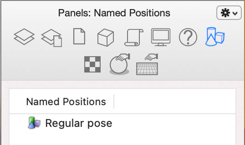
Here’s a tip for using the NamedPositions (that I found out the hard way!)
Before you move anything, select ALL geometry and name it something like “Original Position” or “Start”. Then, move stuff around and save each stage with a unique name. Repeat as needed. With the first step complete, you’ll always be able to get back to the original / beginning state.
I also recommend opening and docking the NamedPosition side-panel – and then using the thumbnail option for quick and easy access to all of the NamedPosition states.
In Rhino, select all objects in the canvas and add them as a new panel. I named it ‘Regular Pose’.
Then, with the procedure from the youtube tutorial, move the objects to the sides to create an exploded view. I also changed the colors of the exploded objects.
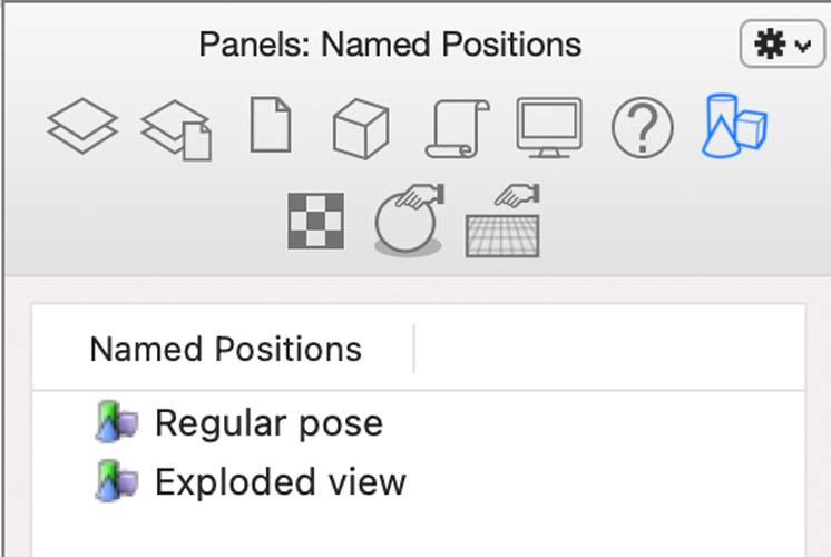
Save this as ‘Exploded View’. Later, you can toggle between them.
Open Illustrator, and draw a line in between the elements.
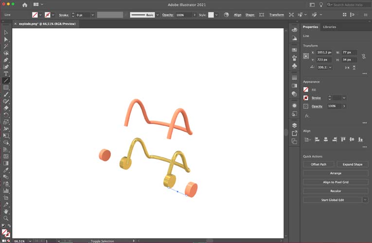
Change the color of the stroke and make it into a dashed line.
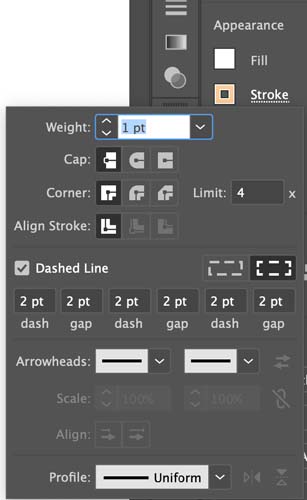
With these settings, draw the rest of the lines.
Done!
Rendering
Rhino has a functionality to render images. I have never used this before and I’m curious to the quality of the output. If this is not satisfactory, I will try other tools like ZBrush.

In Rhino, you can switching from Wireframe to Shaded, and Rendered.
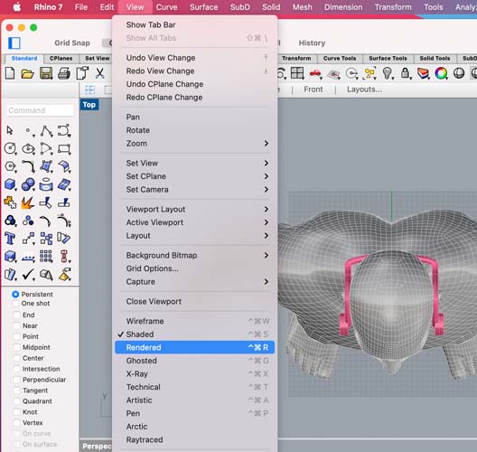
To show the difference between them, this is Shaded:
And this is Rendered:
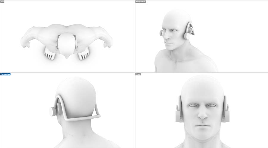
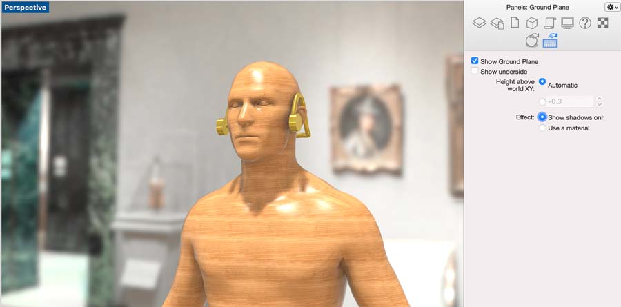
This looks like a pretty creepy guy.. Let’s see what we can do! With the help of this Youtube tutorial I created the render. First start with selecting a ground plane.
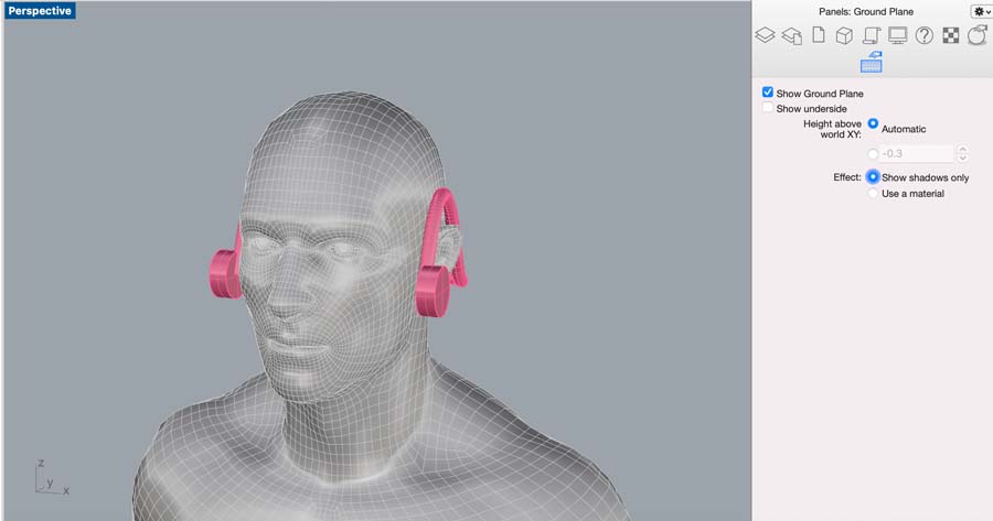
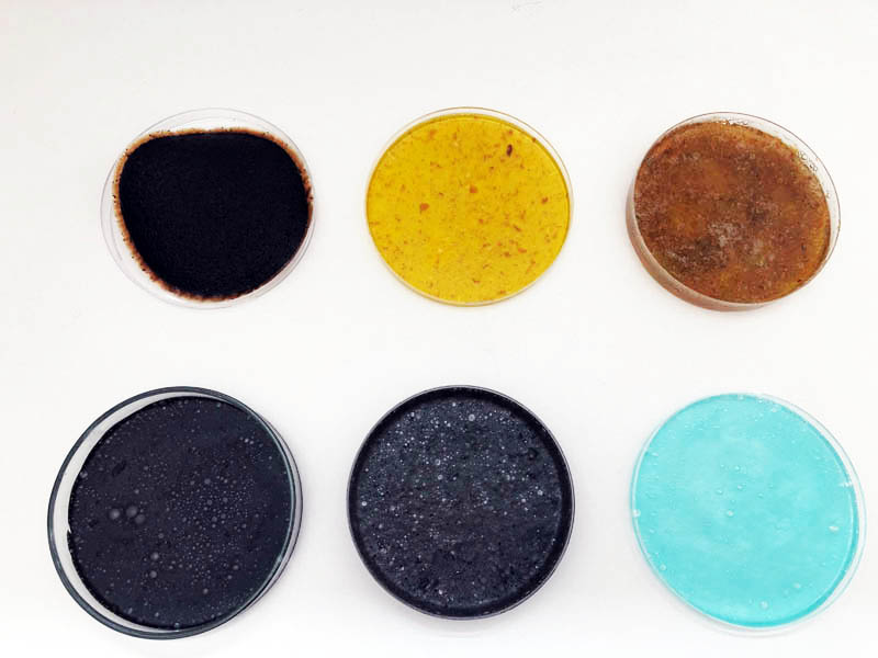
We select the effect ‘use a material’.
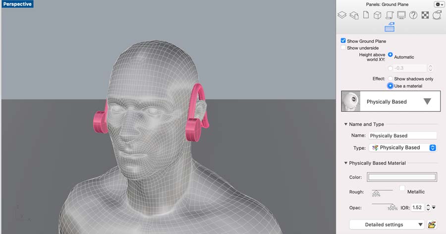
I chose the ‘Diamond Tile’.
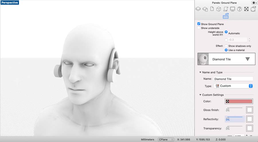
Next, select our guy and open the Material properties panel.
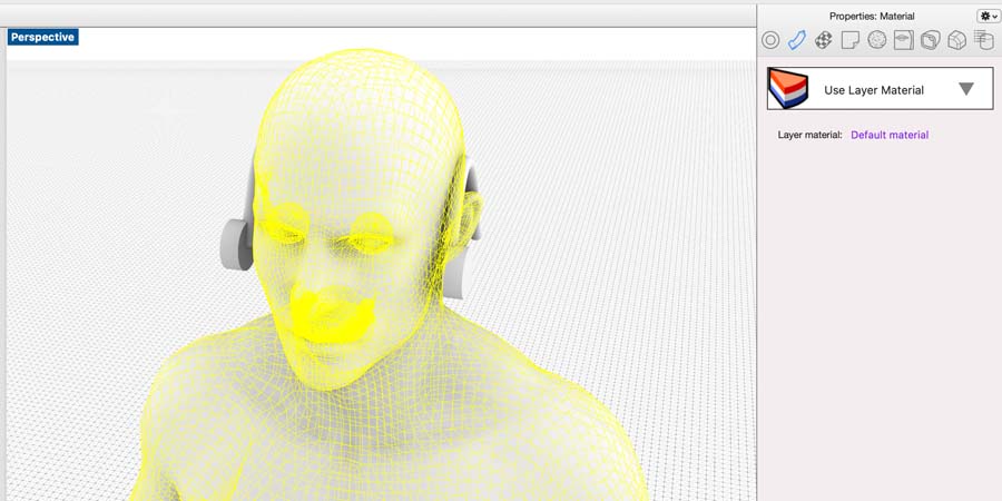
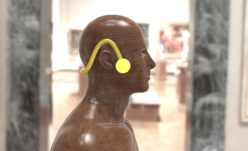
I chose Chestnut Polished as a material.
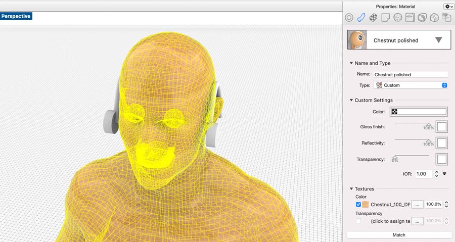
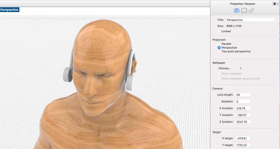
This is how it looks like.
I selected the oorijzer and changed the material to ‘Gold Polished’.
Next, click on the ‘Rendering’ panel.
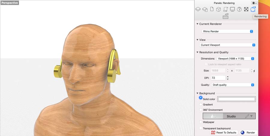
Change the background from ‘solid color’ to 360 environment.
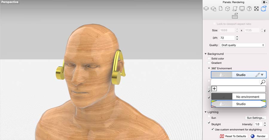
The Museum of Fine Arts (MFA) in Boston is a great background.
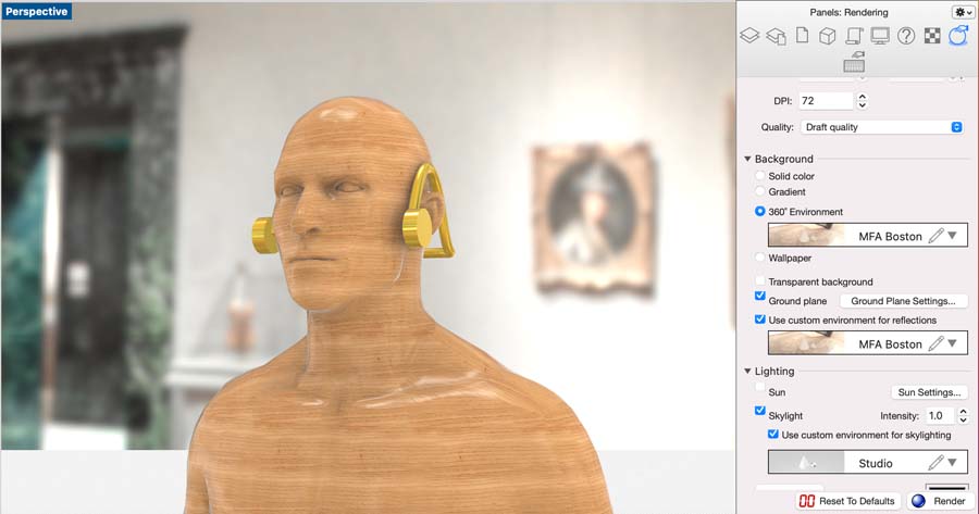
For the ground plane, I’m going to remove the material.
For more contrast, I’ll switch the material from Chestnut Polished to Walnut Polished.
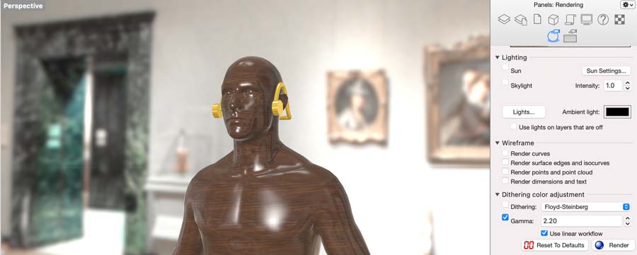
In the rendering panel, we change the lightning settings.
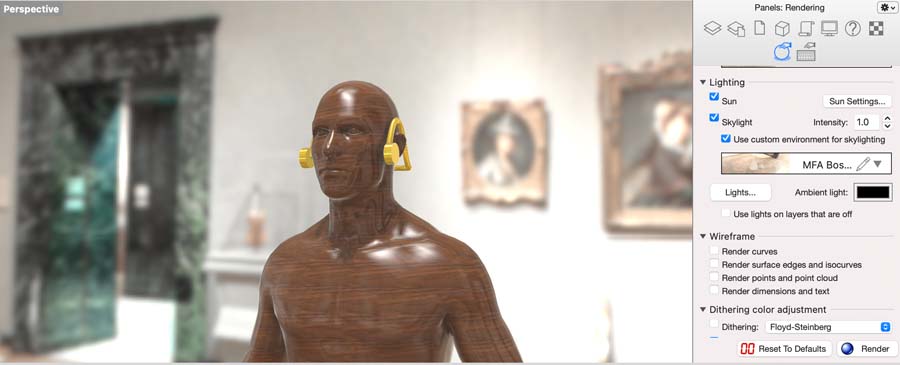
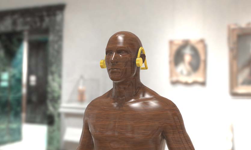
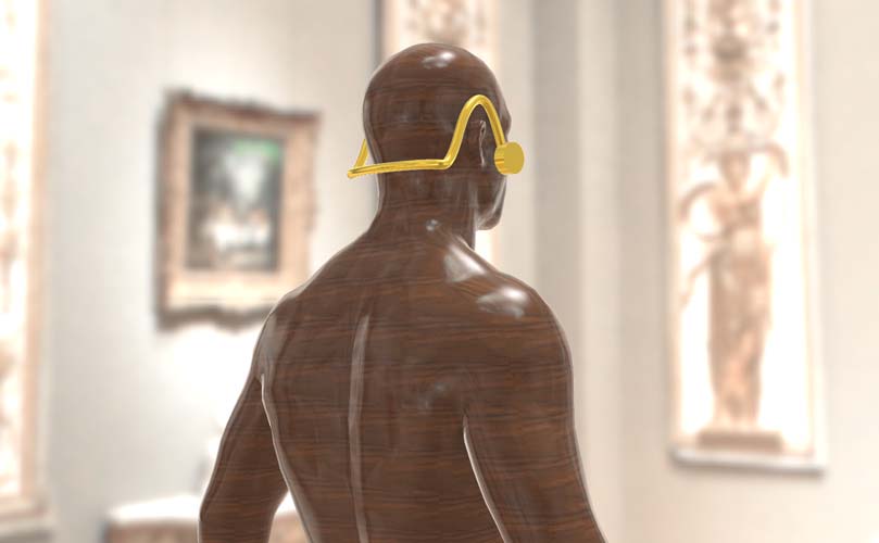
Done! Here are the results:
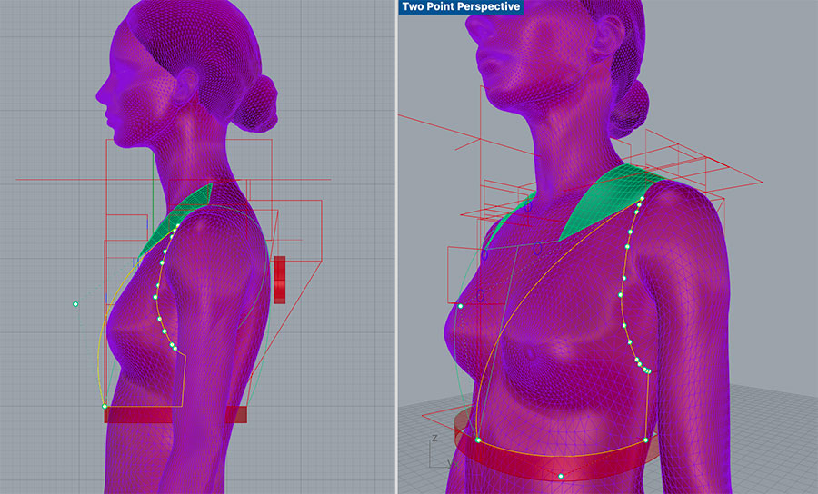
Two-point perspective
Perspective from back
Perspective from front
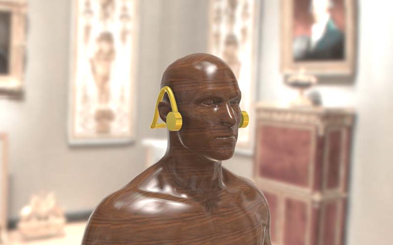
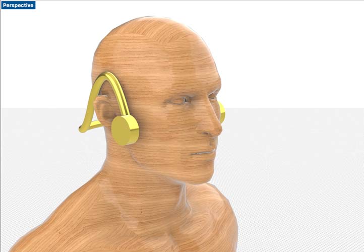
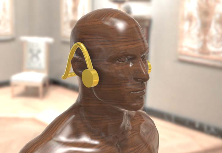
Side view
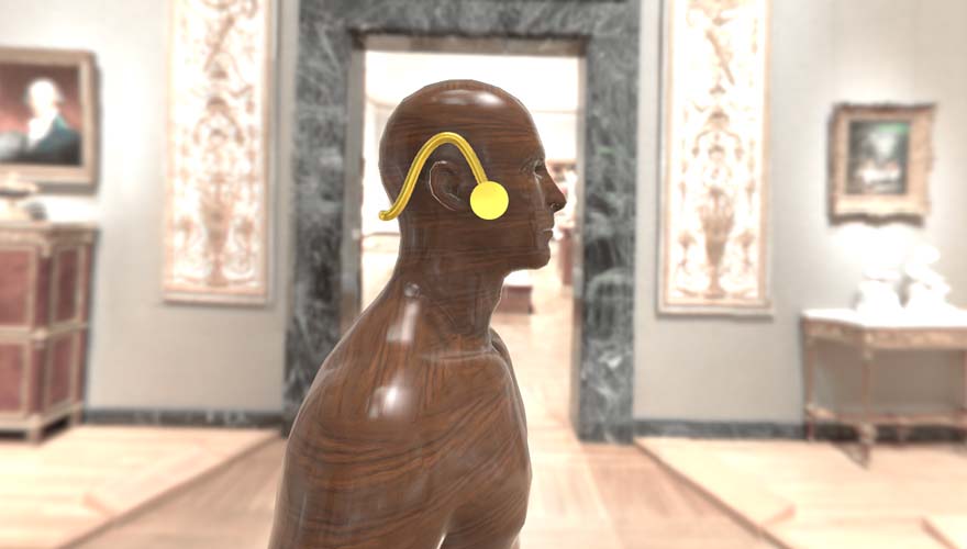
A close-up of the side view
Not bad! I’m quite impressed by the render function of Rhino.
Animation
During Fab Academy, I’d like to learn how to animate objects. The physics engine of Blender is supposed to be a good software tool, and I’m curious to find out. There are also tools in the Adobe package, such as After Effects, Animate and Character Animator. Will add this later when time allows.
Simulation
During grad school, I’ve simulated a couple of projects. For example:
- Computational Fluid Dynamics (CFD) for building simulation, to determine air flow throughout a building
- Finite Element Analysis (FEA) for determining the structural integrity of a topologically optimized beam
It’s been a while since I last did this (over 2 years), and I would love to do this again!
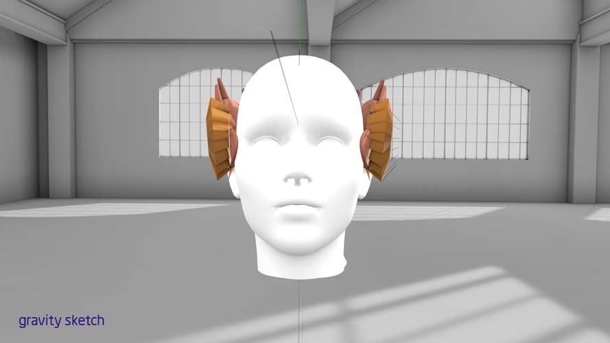
VR modeling
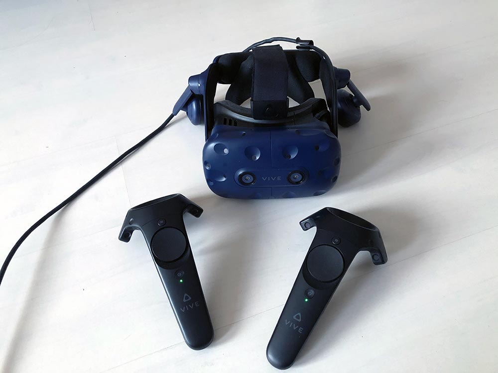
I’ll be designing the oorijzers in Gravity Sketch, a virtual reality application available on Steam. I’m using the Vive headset from my partner.
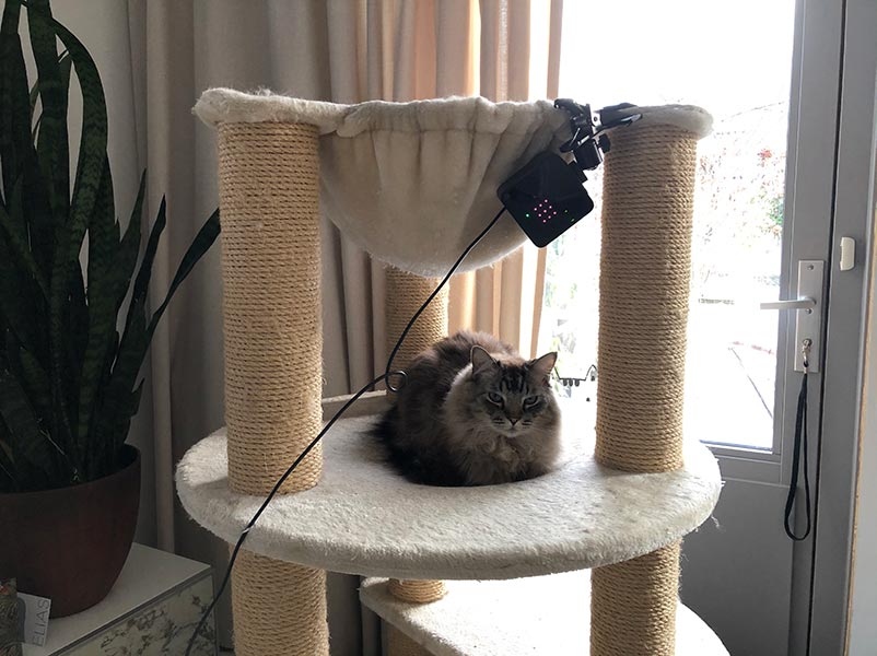
And of course we will have support and careful supervision by my cat Rocky.
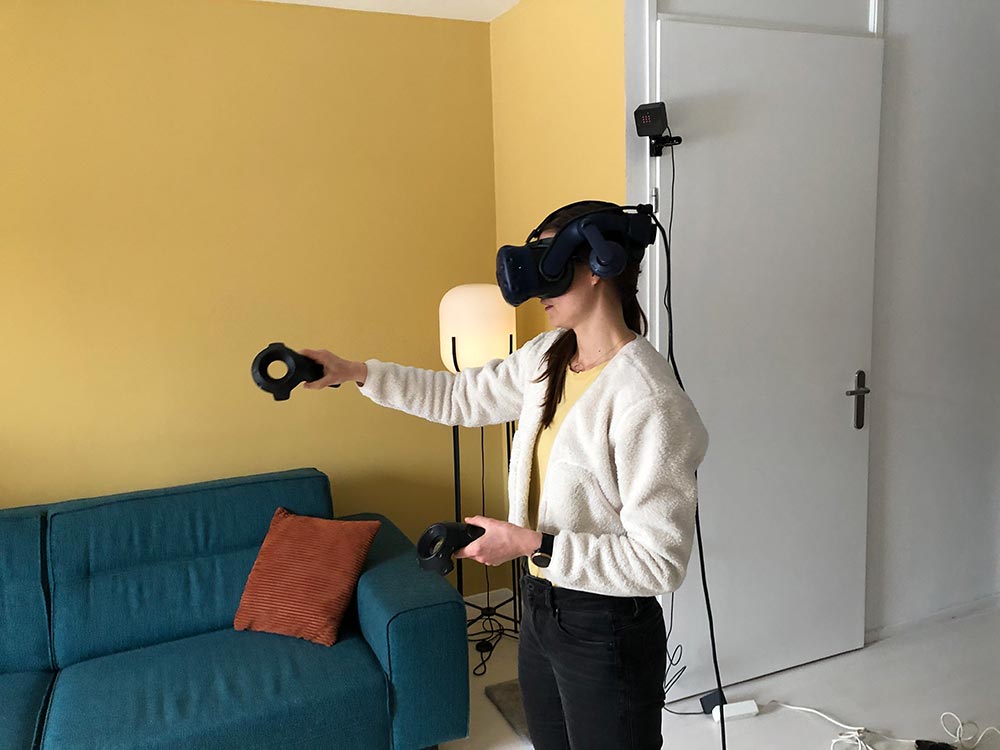
Here is one image of me during the drawing process.
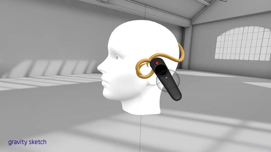
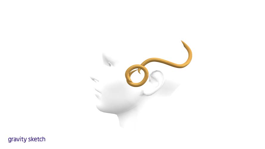
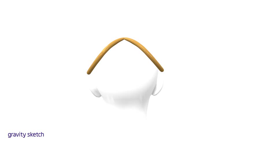
VR oorijzer design 1
The first design is the most simple version of the oorijzer.
Front view (will render this later)
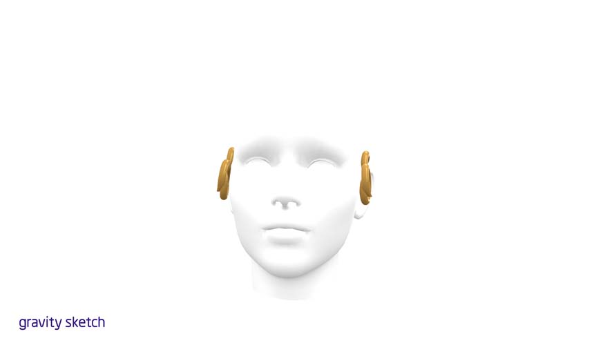
Angled view
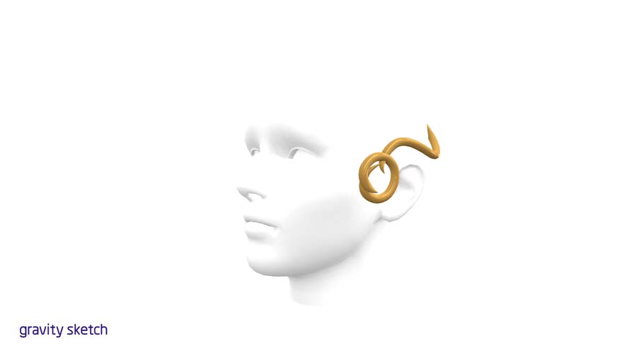
Side view
Back view
That’s not bad for a first time! I’m impressed by how intuitive this process is.
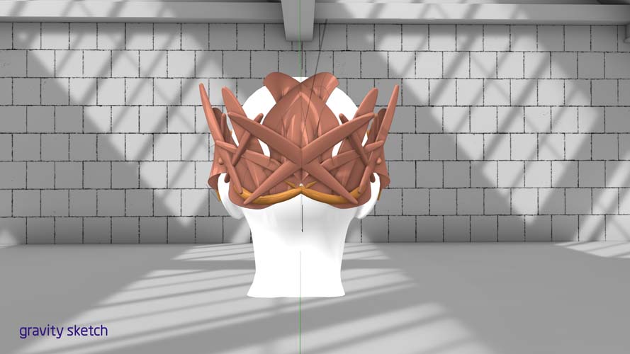
VR oorijzer design 2
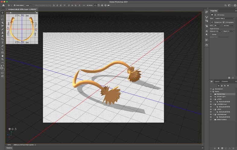
Next, I created a more complex design. I exported it as an OBJ file and opened it in Photoshop.
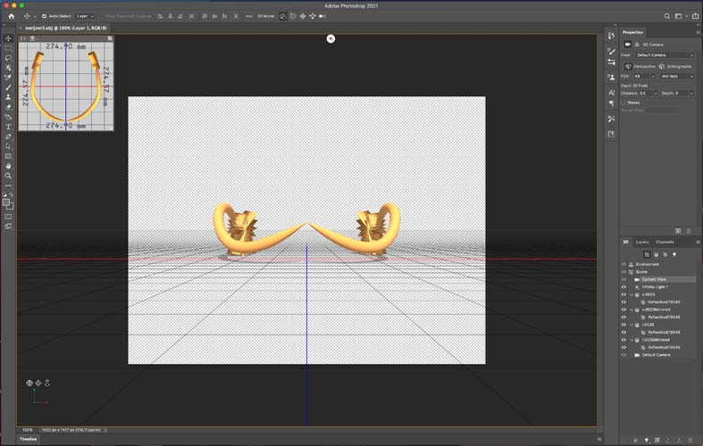
Turns out, Photoshop has a 3D function!
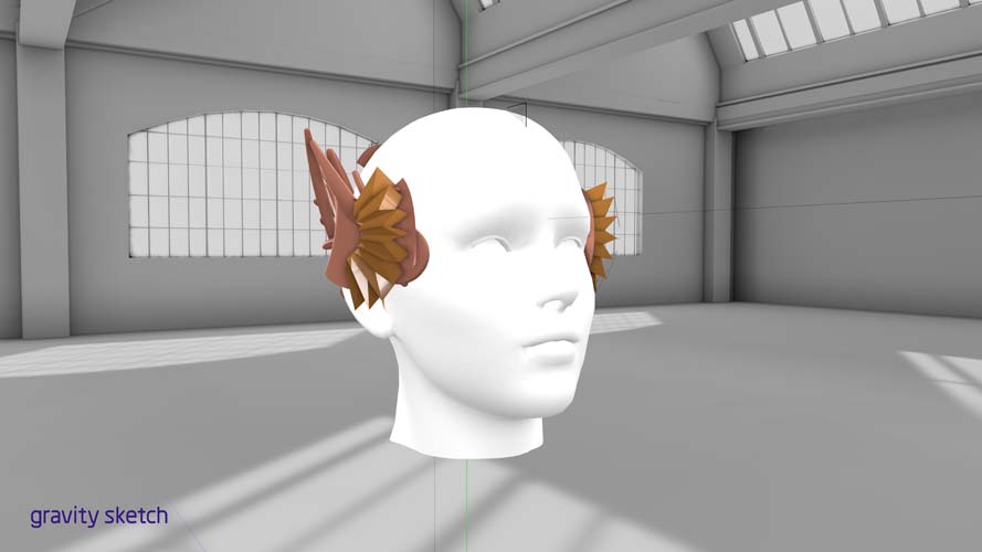
VR oorijzer design 5
A couple of iterations further:
Side view
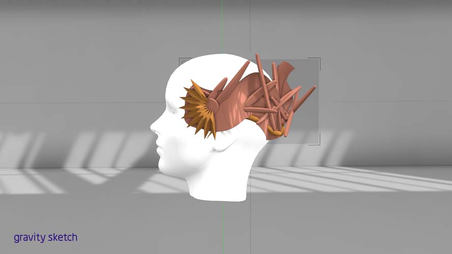
Angled view
Front view
Back view
Designing in VR is more powerful than I expected. I will try to manufacture this version soon!
Downloads
- Grasshopper file
- Rhino file: file size is 65,5 MB. If it’s larger than 10 MB we have to host it externally. That’s why you can download the .zip file from a Google drive.
- dxf file: file size is 15,5 MB so this is also hosted externally.
Explore more like this
Week 17 Invention, Intellectual Property and Business Models
After acing through the technical assignments of Fab Academy, the last two weeks have a lighter load so we can focus on the final project. But this does not mean...
Week 16 Applications and Implications
Propose a final project masterpiece that integrates the range of units covered, answering: