Week9; Machine Design, group-assignment

This week we will design and build a machine with a group. I am in the team with Philip, Paula and Erwin and we have a good idea with a machine that will make Fabacademy-live a little more pleasant
Wednesday Global Class
Neil explained about the different motors and how to use them, He explained how different machines were built, a variety of x-y-z-axis machines were showed.
Weekly Assignment
In my own words
Group assignment:
Make a working machine!
Planning this week
Due to Corona, we have to split up the group in halves to work in the Waag, I am scheduled to be there on thursday (instruction and group assignment) and on monday and tuesday, the afternoons. I work on monday-morning, tuesday-morning and friday, so it is quite a tight schedule. I made my planning around this schedule.
| Day | Lesson | subject/activity | activities |
|---|---|---|---|
| Wednesday | global class | be overwhelmed | |
| Thursday | find info on motors | Idea's for group assignment | |
| Friday | Waag-time brainstorm | think out the machine | divide the work |
| Saturday | think about mechanics | global open time | play with motors (tutorials) |
| Sunday | work on documentation | finish model | family-time |
| Monday | afternoon local Fab time | get my first 3D-print | see what goes well |
| Tuesday | afternoon local Fab time | Try out different options with the print | Documentation |
| Wednesday | presentations | ready to present | fix last things |
Desk-research
Motors and connecting them is new to me. What can I learn:
DC-motors Servo-Motors Stepper-Motors
The Group assignment
This assignment is a group assignment. The team I am in is with Erwin, Philip and Paula.
Brainstormsession
On friday I hosted a brainstorm session on our machine, I earched everybody to think of ideas during the week before and we did 'brainwriting' that is a method were everybody has a A3-paper and draws/writes down their idea and after a few minutes the paper is given to the next person in line. With the paper with already some ideas on it, everyone will add on to the ideas or when something new pops up that is also drawn on the paper. be careful not to critisize anything on the paper, every idea is good, just add on to it. This is done several times so everybody has seen everyones elses ideas. This way you can have a lot of ideas in a very short time. The next step is to make a choice. A nice way is to sort everything but in order to save time we just had everyone look at all the papers and chooses an idea that looks/feels good. This way everyone can give their opinion and we can make a list of advantages and disadvantages of every idea.
The idea
The result is a 'Tap on the shoulder machine'
Then we worked out what we would need for the machine: While everybody was saying things about our I was drawing and writing at the flip-over so we would have a good summary of our idea.
The First spiral would make it very simple A Stick moving at the shoulder combined with a hand tapping. That would mean 2 pivoting points. on top of this we worked out what the next spirals would be:
- We would like a moving shoulder and elbow
- We would like to have a natural look of the arm, hand and chest.
The workflow
We devided the work in parts of the machine. we were a bit in a hurry so we did not really write down everything.
- Erwin would take on the programming
- Paula would look into the chest and arm for making it look humanlike
- Philip would mould a hand and make a wrist and make it tappable.
- I would look into the mechanics of the shoulder and arm bending.
How to connect a motor to a microprocessor....?
What I need is a good understanding of what the possibilities are of connecting the motors to a arduino or so. I asked Erwin to help us out with setting up some basics or pointing us to a tutorial how to start with that.
He did so on saturday: beginnersguide to control motors with arduino
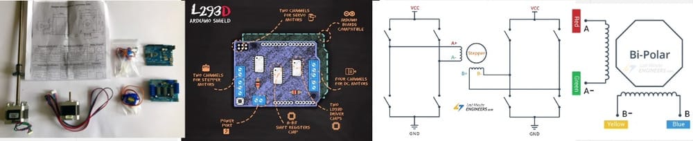
It needs a L293D chip to make the connection with the motor and I don't have that. So I went to the local electronics-store. And the really nice guys at Display-electronics gave me a motorshield containing these chips that hooks nicely into my Arduino.
Back home I had to find out what this shield is all about, It is a remake of the Adafruit Motor-shield and although Adafruit is producing newer versions and sais this is obsolete, it is widely available (and I bought it today). After a thorough search I found a good tutorial including:
- the setup for the arduino-ide
- the code for the arduino/motorshield-combination.
- the physical setup for the motors that I have
- what wire to hook onto what port.
- connecting a power-source.
Lastminuteengineers has a great page including all these features
I followed the tutorials and uploaded the code to my arduino and made a DC-motor working, a servo-motor working.
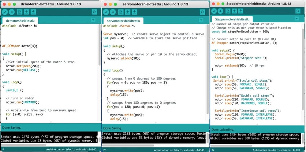 The steppermotor needed a little extra research on the different connections, because the colour-coding of the tutorial was different than mine and I would better use external power, but I did not have the right powersupply.
 Luckily it did work with the USB-power supplied by the Arduino-cable.
Saturday open time
So, I looked at opentime and hoped to find solutions for our moving arm and shoulder, but it did not really ring a bell. I did get forward though with finding ways to program the motors.
Weekend
studying motors, connecting with motor-shield
Talk with science-teacher-friend
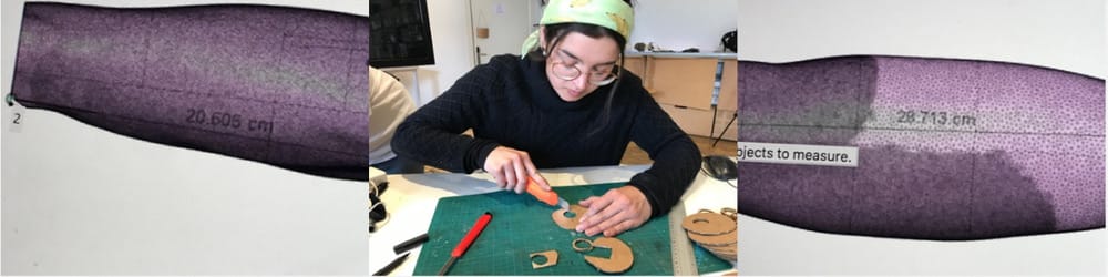
I made some cardboard test-arms at home. The goal was to test the difference between a joint at the elbow and only a joint at the shoulder. And I worked out what the measurements would be of a live-size arm.
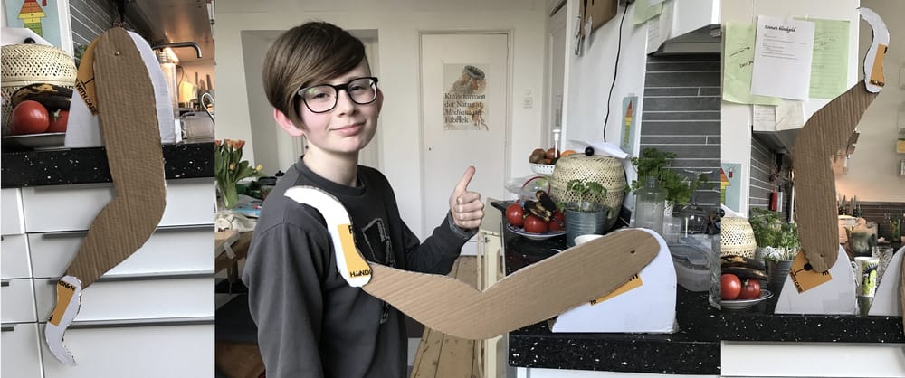 Cardboard arms with/without elbows
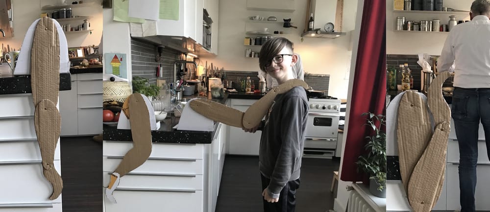 Testing with Arend
Better at elbow, less force on the motors and joints
Testing with Arend
Better at elbow, less force on the motors and joints
Tuesday at Waag
After a weekend trying to find ways to bend the arm.
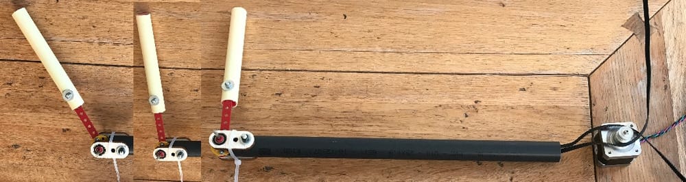
At waag, I looked at materials and found some PVC-pipes that is used for electric systems in homes. It was Easy to make the arm with this and use some cardboard to make a leaver on it. so it very rudimentary will move up and down at the elbow.
 After that I connected the stepper-motor to check if this would make it move the arm.
Tuesdaynight at home
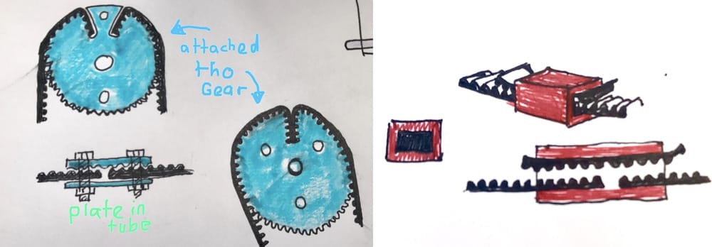
New model with gears at shoulder and elbow. This way the toothed belt can be guided inside the pvc-pipe of the upperarm.
I worked on it with my old meccano-kit, took the whole evening. It looks great but...
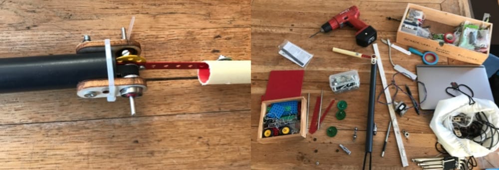 Does not work. The teethed belt is slipping over the gear in the elbow. Maybe the belt should be tighter, but that does not seem right.
 Hmmm, maybe it is easier to fixate the belt at the elbow or to make a larger gear for example 40 mm in stead of 14mm
Working online to find the right gear in fusion. (2mm teeth-space) (it gas a name)
Hmmm, maybe it is easier to fixate the belt at the elbow or to make a larger gear for example 40 mm in stead of 14mm
Working online to find the right gear in fusion. (2mm teeth-space) (it gas a name)
Wednesday at Waag
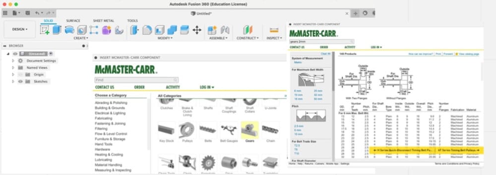
Through the download-McMaster-car-parts-option it was very hard to find the right gears, because I did not have any system-numbers or real measurements and there were only/mostly american parts in inches in stead of mm.
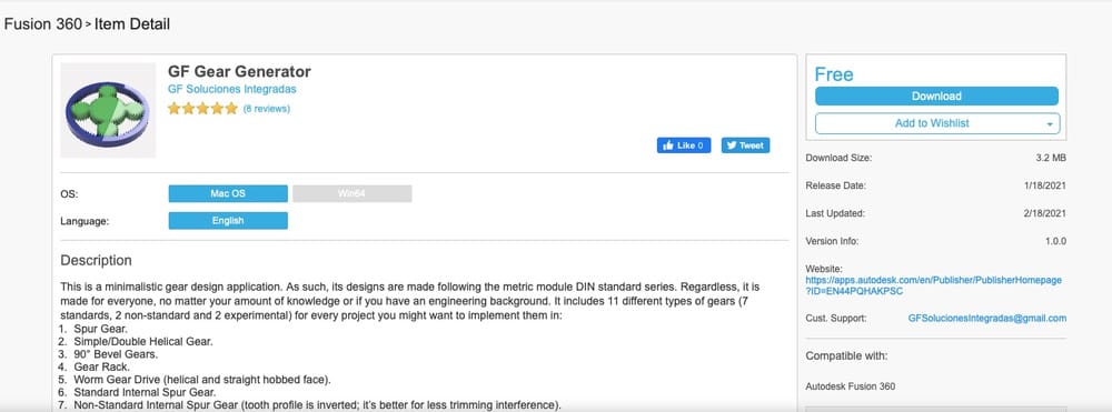
Then I tried to download a gears-plugin, GF Gear-generator but with several tries I could not make it show up in my Fusion-360 screen.
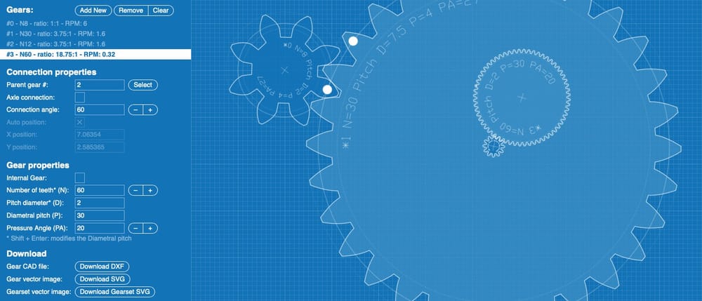
 Third try was looking online for a gearmaker that would export a DXF-file or SVG. I found a great one at geargenerator.com, but that costs 2 dollar per gear exported.
 After that I found my solution: a great simple gearmaker with svg as an export.
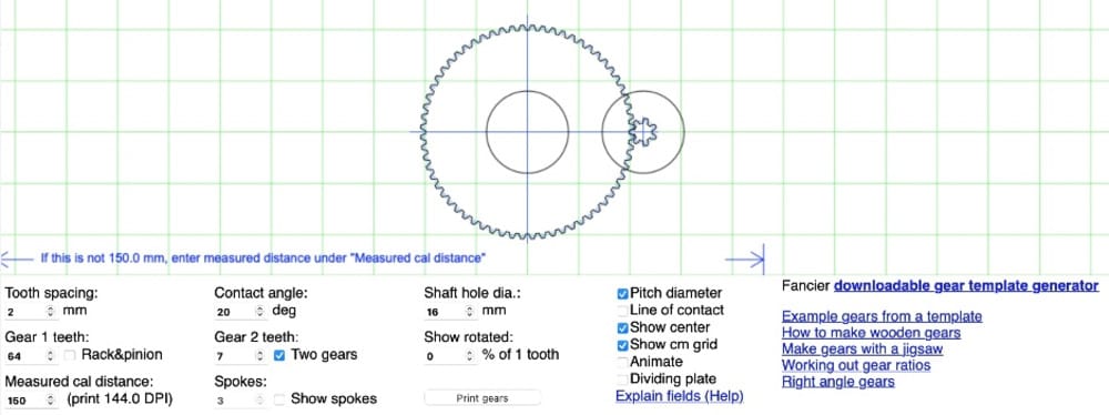
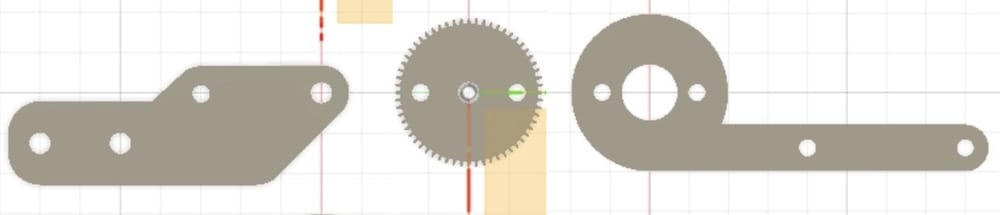
I made the gear with 60 teeth, and 38mm diameter. Working in Fusion I made the set of parts that would fit the elbow.
 In real life trying it out in 5mm plywood models. Gear is a little too small, changing the offset in lightburn to 0,115mm does the trick. Now make it in acrylic.
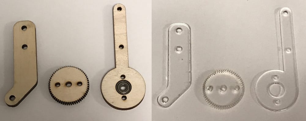
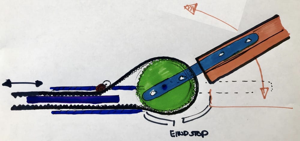
I found some pieces that are 6 mm thick so it fits the belt perfectly. It is gard to cut though, but at speed 10 and power 90 it dies the job in the upper-left corner. It looks fantastic, like it is straight from a meccano-factory.... And works great, the toothed belt fits perfectly and won’t go anywhere! With this I solved 2 problems, the sliding belt wont slide over this bigger gear, because there are more teeth to slide over, and the gear is 3 times as big as the gear on the motor so the force that is needed by the motor is 3 times as small. that will give enough room for the weight of the lower arm and the foam-hand to be lifted.
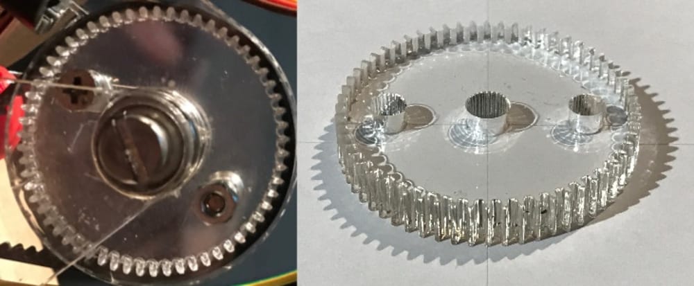 I made some circle-shaped sides a little bigger then the gear so the belt won’t slide off. These sides have 16mm holes in the middle so the skate-bearrings will fit in. And they have small arms sticking out to fit to the fore-arm. And luckily the two arms fit together in the pvc-pipe and even if they are bolted in, they leave some space for electric wiring.
With the bigger gear the belt won’t fit in the pvc-pipe of the upper-arm anymore.
I decided to make the pivotpoint higher, that way the elbow can fold further and the lower belt will fit straight into the pvc-pipe.
I made some circle-shaped sides a little bigger then the gear so the belt won’t slide off. These sides have 16mm holes in the middle so the skate-bearrings will fit in. And they have small arms sticking out to fit to the fore-arm. And luckily the two arms fit together in the pvc-pipe and even if they are bolted in, they leave some space for electric wiring.
With the bigger gear the belt won’t fit in the pvc-pipe of the upper-arm anymore.
I decided to make the pivotpoint higher, that way the elbow can fold further and the lower belt will fit straight into the pvc-pipe.
So then I lowered the arms sticking in the fore-arm so the both arm-parts are in one line when straight.
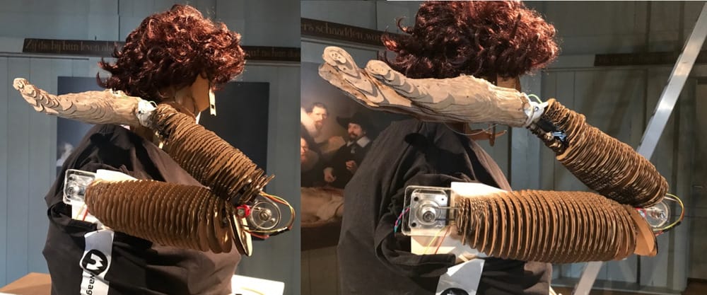
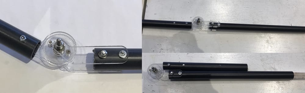 It works really nice, the joint is really folding double and the looks are good too.
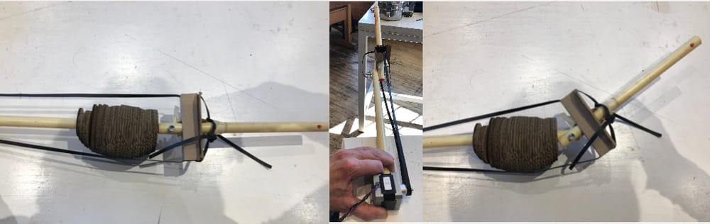
Time for my groupmembers to work with my roughly finished product. At the end of the day I connected all the parts and left the working elbow with pipes at the Waag for the other group-members to work on it, since they would be there other days than I would. The elbow is ready and the wrist can be measured and attached, and also the electric wiring can be made through the pipes. I send them these pictures, and the measurements of everything. Mattermost is our friend.
Weekend at home
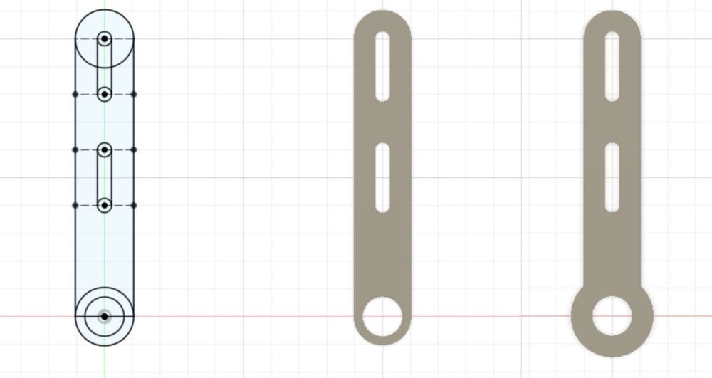
Next part is to get the higher belt part back into the pvc-pipe. I decided that it should be fixed to the same frame as the elbow-axis and the belt can go in 45 degrees back towards the pipe.
To have it role smoothely I made some bearings inside my rolling part and adjusted the thickness of the rolling part to the desired height in the pipe.
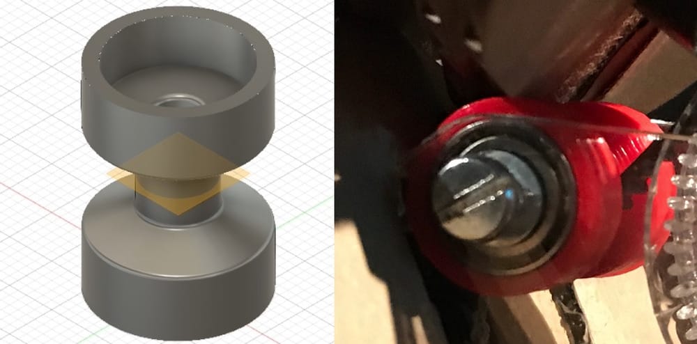
the shoulder fixed
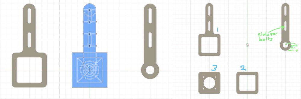
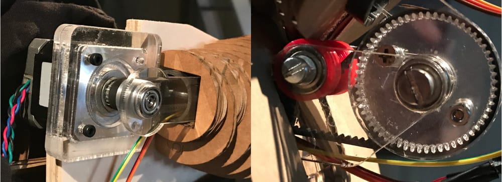
At the shoulder there will be the stepper-motor and with the slipping-teeth I am a bit worried about the tightness of the belt, so I decided to make a fixing that can slide in order to tighten the belt. I found another skate-bearing that will fit onto the stepper- motor-axis which makes it easier to fixate it on two sides and therefore make a tight fit without weird side-forces.
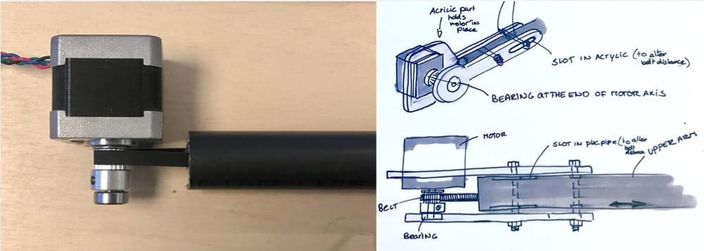 Turning the gear on the axis around will line up the toothed part nicely in the middle of the pipe. This way only the motor needs to fixated in the right spot.
After the great succes of the acrylic parts for the elbow I will make the motor-fixture the same.
Turning the gear on the axis around will line up the toothed part nicely in the middle of the pipe. This way only the motor needs to fixated in the right spot.
After the great succes of the acrylic parts for the elbow I will make the motor-fixture the same.
 and I would like to glue them together with this special glue that really melts it together.
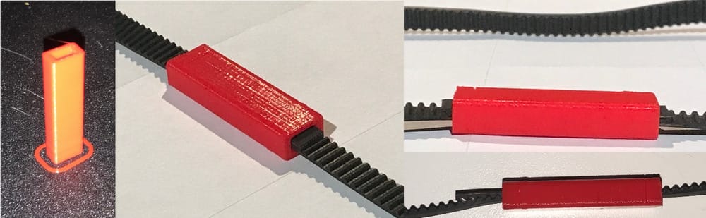
 One other complication is that the toothed belt does not have anything to fix the loose ends together, there are some examples at Waag, where it is bolted to a piece of wood, or with a large 3d-printed part, I looked for inspiration online and found plates with teeth that can be bolted on and ways of cutting the belt halfway and glueing the parts together. Also with bigger belts it is possible to join them with small pinns sticking in sideways. I don’t really see possibilities.
What I really like is the idea of sticking it sideways into a toothed gap and it cannot move out.
Another thing I like it that it seems to grip itself very well with the teeth if two parts are put on top of each other with the teeth towards each other. This made me think of a very simple and reusable way of binding it. With a small rectangular pipe which will hold two parts together using a loose third piece of toothed belt.
One other complication is that the toothed belt does not have anything to fix the loose ends together, there are some examples at Waag, where it is bolted to a piece of wood, or with a large 3d-printed part, I looked for inspiration online and found plates with teeth that can be bolted on and ways of cutting the belt halfway and glueing the parts together. Also with bigger belts it is possible to join them with small pinns sticking in sideways. I don’t really see possibilities.
What I really like is the idea of sticking it sideways into a toothed gap and it cannot move out.
Another thing I like it that it seems to grip itself very well with the teeth if two parts are put on top of each other with the teeth towards each other. This made me think of a very simple and reusable way of binding it. With a small rectangular pipe which will hold two parts together using a loose third piece of toothed belt.
 I printed this part at home and made my family do a strength test, and it works.
Tuesday at Waag
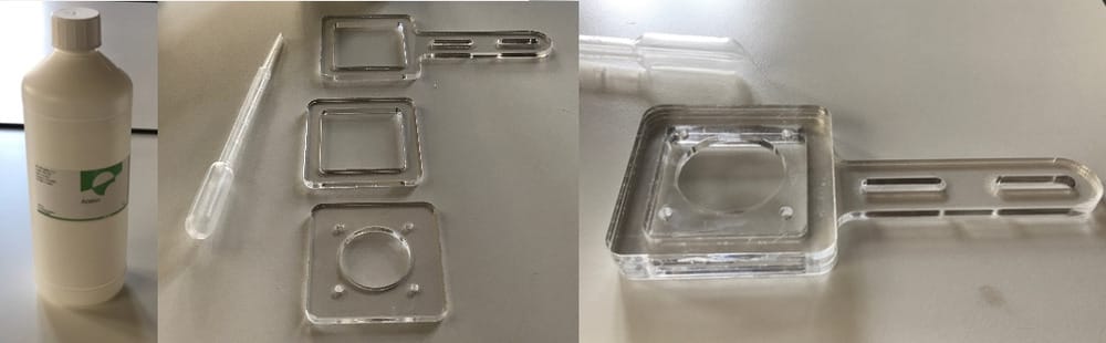
At Waag My friend the lasercutter cut out the different parts to hold the motor in place.
 I decided not to make holes to connect the different parts, because I heard there was a great way of gluing acrylic together, where it melts together and really becomes one part.
Henk explained that it works with acetone which you can seep between two parts and it melts the top layer of both parts together.
He showed me with a leftover part and the I tried with the real parts in the bio-chemical lab. It made a nice sturdy fixture and with the small screws I could fit the motor perfectly in place.
I decided not to make holes to connect the different parts, because I heard there was a great way of gluing acrylic together, where it melts together and really becomes one part.
Henk explained that it works with acetone which you can seep between two parts and it melts the top layer of both parts together.
He showed me with a leftover part and the I tried with the real parts in the bio-chemical lab. It made a nice sturdy fixture and with the small screws I could fit the motor perfectly in place.
 Fitting everything together and
Hey it works!!!
Fitting everything together and
Hey it works!!!
I could join everything together and do some tests with my simple code from the first saturday and it is working. Yesyesyes.... Sadly enough it is not working with the much fancier code that Erwin made.
Everything should come together.
Now I have all the time of the world to help the other group-members in their work.
Philip is working on the hand, but has not thought out the connections of the motor and wiring yet. Erwin will work on that with him and I started to help Paula with fitting all the cardboard circles on the arm. She sliced a model with a round duffel through the slices with the diameter of the pvc-pipe but because of my fittings to the pipe.
 Some of the holes need adjustment. So I will happily cut away parts of the cardboard.
It was really nice to put together the fore-arm and the elbow again, Paula and I were a great team of surgeants trying to fit the bolts carefully between the cardboard slices.
Some of the holes need adjustment. So I will happily cut away parts of the cardboard.
It was really nice to put together the fore-arm and the elbow again, Paula and I were a great team of surgeants trying to fit the bolts carefully between the cardboard slices.
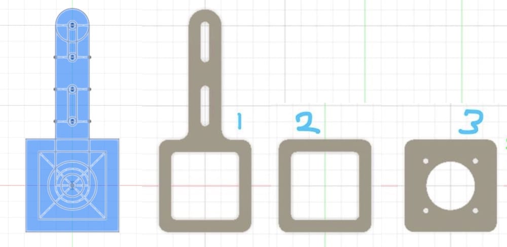
Paula had made this vertical wooden plate so we would have a sturdy base to connect everything to and I fitted my stepper-motor-connector to it, by making 2 holes for the bolts and a big square hole for the motor itself. this way, the weight of the motor was on the board and the arm and belt could still be adjusted.
At the end of tuesday, most of the arm-parts are not together anymore, because all the other people have to fit their parts to the pipes (Philip the hand, Paula the slices and Erwin the motor).
Erwin was afraid that he blew-up my new motor-shield because nothing was working anymore and it was very hot. I said I could go to the electornics-shop in the morning to get a new one and he even promised to pay for mine. But he had to catch a train and at the end of the afternoon I tried my own set-up again and luckily it was working. So I did not have to contact my electronics-shop to get a new one. But his code was not working with the steppermotor yet, and on the other hand, the servo-motor for the wrist was not connected to the arm yet, so at the end of the day we did not have anything working.
I suggested that at least we could hook up my arduino to the elbow and his arduino + code to the wrist and have it working synchronically by setting the times that thins would take. Erwin agreed that that would be a good back-up-plan, but he wanted his library-problems fixed.
Tuesdaynight at home
Tuesdaynight I worked online with Erwin, he sent me some simple code (based on my tutorial-code) to work on our back-up plan, I uploaded it fitted a button to pin2 and Ground and yesit worked fine. Then I suggested to upload his new code to my arduino so he sent me the fancy code and I uploaded it, (I did not connect the extra buttons, but did connect a servo to the right pins) but it did not work at all.
So we called it a night and I gave Erwin some extra things to think about.
Wednesday/deadline
On wednesday there were a lot of loose ends, and especially since my part was the heart of the arm I was the last to be able to reconnect all my parts. The connections of the hand and wrist had to be fixed, because when the motor was glued to the arm the electric wires were forgotten to go through the pipe. Philip had to think of a way to lead the wires through his wrist. I helped him out by thinking out where he could drill a hole, and helped him out again to drill an extra slot because he did not drill towards the middle of the arm. I helped Paula by fitting all the parts
Sadly enough the size, the changes in the design and the last-minute fixtures of the hand and wrist resulted in a lot of extra weight. The lightweight-idea of the beginning of the design 2 weeks ago was long gone. It was very good that I had decided earlier that the pivot-point should be at the elbow instead of the shoulder and that I made the gears bigger there, so the motor would have enough power.
Learnings this week
This week was a bit complicated, I had some family-matters that were taking attention but I really made myself very useful. We have two people in the team that are not very technical, so I took on a lot of the technical parts and had to help out with quite some design-decisions.:
- I really learned that the skills that I already have come in very useful during this course. I think a sturdy base of Delft technology helps a lot
- In my head there are always 10 solutions popping up if a problem needs to be solved, I am also very capable of overseeing these different solutions and think of advantages and disadvantages. But I really learned in my job as a industrial designer to keep an open mind to all those solutions and compare them equally and only then
- I learned about myself that when I work with people I can be more openminded to their way of thinking and find better ways to keep communicatin when the other is not as design-open-minded as I am. I think that the fact that I recognize this is already really helpful for next times in life.
- the technical part of turning on the motors with the H-bridges and code was really nice to learn. It was great to work with Erwin on this, I learned a lot about the different motors and how to connect them with external power.
- the race against the clock, the differences between the team-members and the easter-weekend just before the presentation did not help to get everything ready in time. but with hard work, forced tolerance towards other people and fake it until you make it it was done in time, I am quite proud of that.
Links to Design-files
here are the links to the designfiles of this week. Files I used to lasercut the acrylic:
Files I printed on the 3D printer: