Week13, networking
This week is all Networking
Wednesday Global Class
Neil is explaining about wired networks, masters and secondaries, I2C with STL and SDA. About wireless networks, networking and communication.
Weekly Assignment
In my own words
Group assignment:
- Connect two projects with each other Individual assignments:
- design and connect a network, using a protocol with adresses. it should be expandable to more than 1 node
Planning this week
| Day | Lesson | subject/activity | activities |
|---|---|---|---|
| Wednesday | global class | make this plan | |
| Thursday | local class networking | group assignment connecting projects | |
| Friday | 'work' for my work | build board in KiCad | print board |
| Saturday | global open time | solder board | |
| Sunday | work on documentation | connect new board with elvis | family-time |
| Monday | get everything working | see what goes well | |
| Tuesday | afternoon local Fab time | get the last things ready | Documentation |
| Wednesday | presentations | ready to present | fix last things |
networking instruction
Henk explained about Baud-time, asynchronous serial, ESP and I2C.
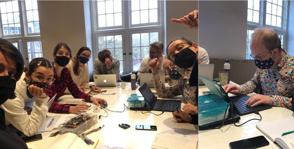
Group assignment
It was up to us to do the group assignment, we decided to do the group assignment with the entire group. Luckily we had Erwin who started writing code in good spirit.
 First Erwin wrote a great little program to find out the standard addresses that come with the I2C modules.
We hooked up an LCD screen and a OLED screen to an arduino uno and combined the different programs to show that we could address both.
First Erwin wrote a great little program to find out the standard addresses that come with the I2C modules.
We hooked up an LCD screen and a OLED screen to an arduino uno and combined the different programs to show that we could address both.
Then we started to work with the Asynchronous Serial which seemed a lot harder, Erwin could not get the sender to give the right commands to the nodes (everything binary changed to decimal), but after we changed the program on the nodes in such a way that it would listen to the weird sender messages it was possible to let them work. it was impossible thought to let them work in a synchronic way, which would be weird, since the sender would repeat the same messages over and over again. For more information on this see our networking-group-page
Individual assignment
Design and and connect a network,
Using a protocol with addresses. it should be expandable to more than 1 node.
I decided that my Senslu2-board was probably not capable of doing all these tasks since it was only with a ATtiny412 and I was afraid that the I2C libraries were too big.
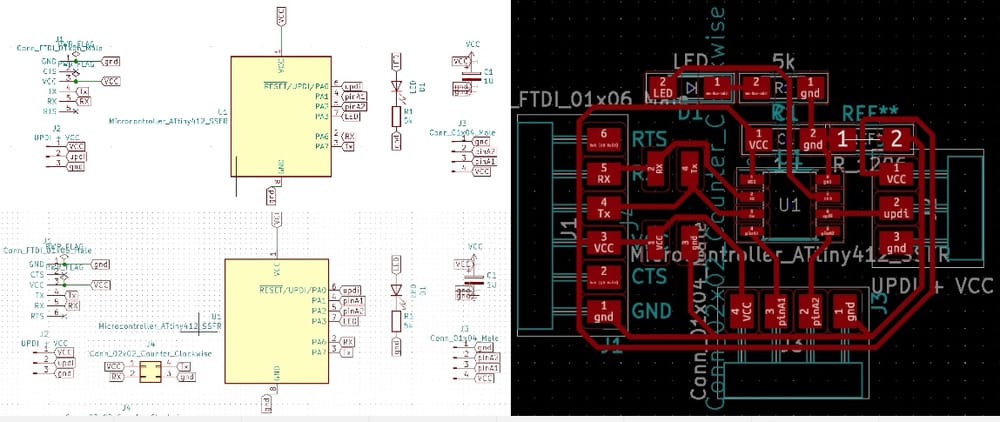
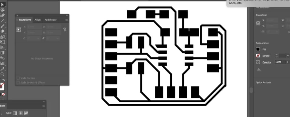
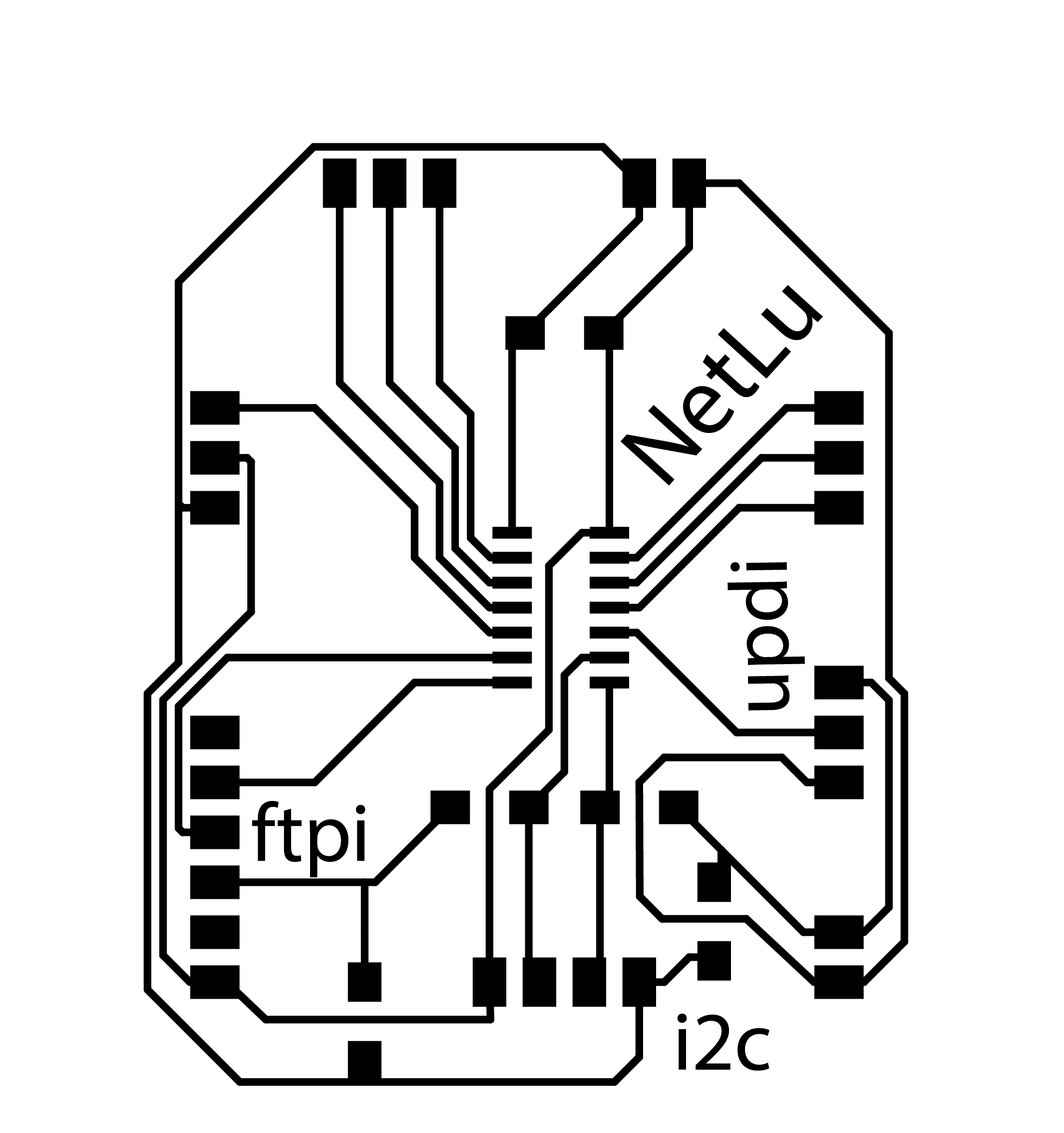
So I made a new board, based on the EE-schema that I already made last week for the Attiny1614. (which I did not finish because there was no milling-time left at Waag)
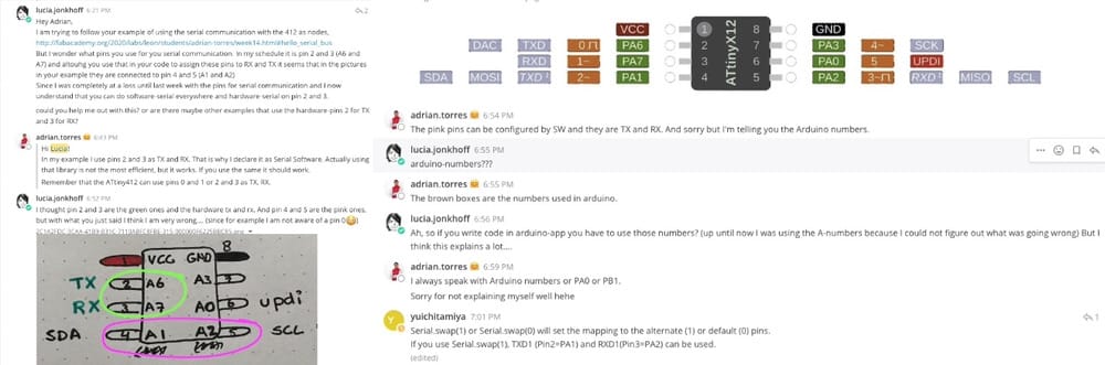
With the information I learned this week it was nice to see that there are allocated pins for TX/RX SCL and SDA
On friday I watched the lesson on networking of Daniele of Kamp Lintfort ,
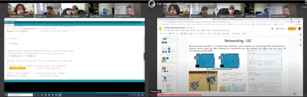 who explained really well how the connections between the different mothers and Nodes work. and he explained about software-serial and hardware-serial. And which components you would need in the setup. for example the pullup resistors on the SCL and SDA.
Notes from friday:
Serial
Attiny has a set with hardware serial, if you want it on different pins you'll need Software serial. but then the microprocessor has to work with it: Library Slow speed
if you use serial.Print forText and serial.Write for bite Addressing system In serial there is no addressing system by default You need to write addressing in software Tx als broadcast, receiver can read a number or string of numbers to address it to a certain node
SPI
Serial peripheral interface Miso, mosi sck Cs1, Cs2, Cs3, ... cable select or ss1 slave select if low this slave is selected, if high not selected
Only one slave can be selected at one moment A new pin is needed for each slave You can still use it to program the attiny with it There are coding libraries for Arduino for this.
I2C I-squared-C
All microcontrollers have i2c
No cable select pin Bus two pins SDA SCL Connect more that 100 nodes Only communication with one of the 100 slaves Slave has an id (number) master is unaddressed (perfect for passing this week) Sensors work often with I2C a lot can be connected to for example adafruit imu bmp180 z Read the data from one sensor at the time
Interconnect the ground again else there is no reference pull-up resistors added by 4,7k for longer wires. One for sca and one for sdl. Very long cable you need stronger pull-ups and lower resistor. (with 5 or less boards it also works without.)
If there is no hardware I2C it is possible in software, but hardware is much quicker, more stable and easier.
friday at home and shopping
With all that knowledge I worked out that I needed some extra resistors on my setup for my board and decided that I could fit them in on the way to Amsterdam. It would be nice to print my board on friday, so I could hook everything up in the weekend.
I did not figure out how the nodes would look, but as a first spiral I would use the standard I2C boards in the electronics kit. Or my good old elvis or senslu-boards. They have the 412 on it and some LED can be connected to it. As a back-up for a first spiral for this I bought myself 2 breakout-boards for the ATtiny and together with my breadboard I can make it work in the weekend.
Friday-afternoon Waag-time
In the train on the way to Amsterdam I was very disappointed, because KiCad simply told me that the EE-schema of my 1614-board was missing and I could not change anything anymore.
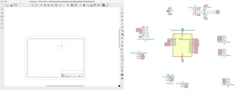 So I had to start all over with my design. Which was a pity, since this was my first 1614-board. So there was no base to start off with and I had to redo all the assigning of the pins and everything.
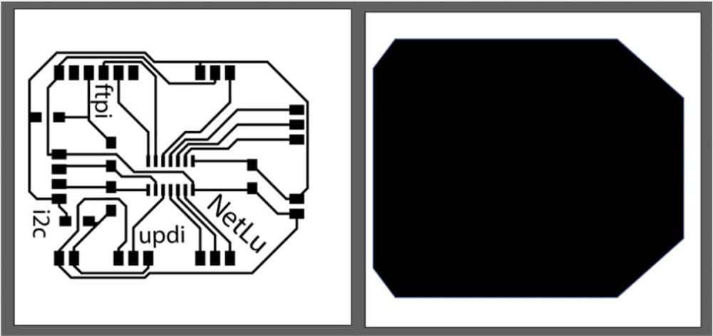 At waag it was really busy. Douwe milled in the morning, Phil was milling when I arrived and Nicole was in line to mill after that. And everybody had to mill both the sender and the nodes so it took quite a while. Eventually I milled as very last and poor Michelle had to run to catch her train after I finished 20 minutes past 6.
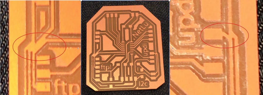
In the train I noticed that not all my threads were milled well and I had to cut away bits and pieces to avoid shorts.
Saturday open time
So, I was convinced with the knowledge of this week (the group assignment we hooked up the I2C in no-time and struggled with the Serial for the whole afternoon that it would be easiest to use I2C.
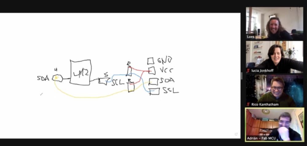
But when Loes asked at open-time how she would connect the different boards and if there is a standard connector-set for these nodes she got a lot of explanation about the difference between the two ways of communicating and that it is way easier to use asynchronous serial if you would only have a little amount of communication (like for instance reading out a sensor)
 This opened my Eyes again to new things and I learned that Adrian is quite a talented sketcher.
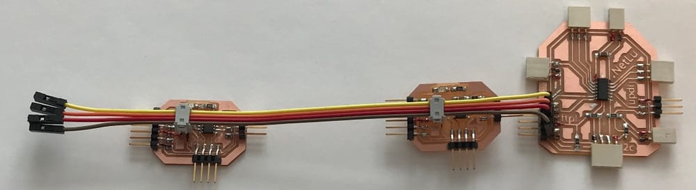
Mean while I was happily soldering away, my Board looks fine and I made a new UPDI, because for mysterious reasons my old one was not working anymore. And I milled a new one during the group-assignment on thursday.
Sunday
Since I am going to try my networking-assignment with hooking up asynch-serial I needed to add some extra pins to my board to connect the RX and the TX with the other boards. I bended these great pins so I could solder them on top of my FTPI-pins. It looks great.
I was so relaxed about everything that on sunday I decided to clean up my documentation of the first few weeks and have it ready for the global evaluator on Nueval. And hook up everything with the networking on monday.
Monday at Home.
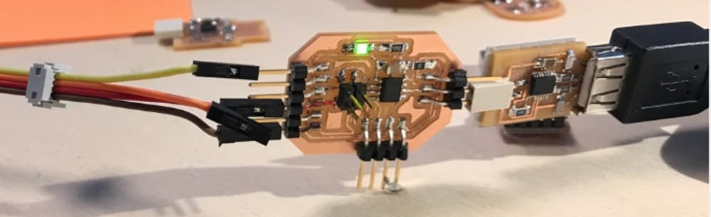
So I started hooking up everything, but first had to check and debug all these different boards that I finally finished this week. My senslu-2 board was working great, Since I finally found out what the right pins are for the RX and the TX I was able to read out the value of my sensor. My networking board was able to light up the LED-set that I made for the output-week.
Only thing that did not work was the new UPDI. but that has everything to do with crooked soldering I found on my picture. all the pins on one side ot the board fell off their footprint so they are all connected to each other. the biggest short in Lucia's Fab-history, hahaha.
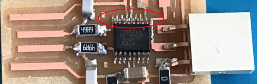 I will use Henks UPDI to upload programs to my boards and fix this one later.
Trying the asynchronous Serial network
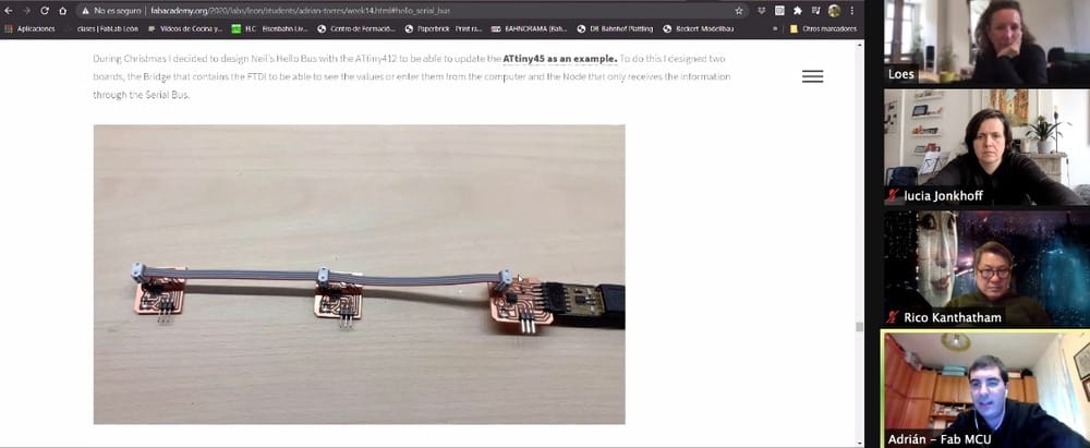
I looked at the site of adrian for a nice example for the asynchronous serial connection.
His code was with software-serial and on pins 4 and 5. I was struggling the last weeks with the TX and RX because the very first board we made was not right and since then I was quite quite confused. Since I only planned to use serial during the weekend I had to work with the boards I had at home. Sadly enough I could not get the 412 on the breakout-board to connect to the UPDI. So I could not program them. As a back-up I started working with my good old Hello-Elvis-board from week6 and my LuSens from the input week. all my boards have different setups for the TX and RX. hmmmm
I tried all these different setups with different TXes and RXes for the different boards with the basic code from adrian and his examples but with no success.
Then I got really frustrated because there were simply too many variables that I could change and I could not even remember what code was on what board. because I was really confused, I even asked for help on mattermost
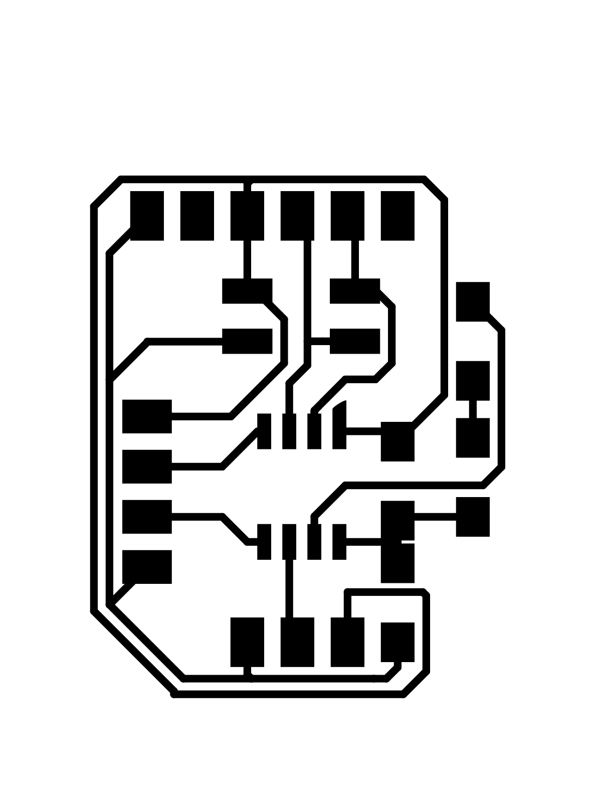
I need to simplify this for myself and make some Nodes that are the same and have a standard set of possibilities and a LED build in that can show that it is working.
Tuesday in Waag
Milling part 2
I designed some nodes according to Adrians example but with the RX and TX on the pins that I understand now.
 and I went to Waag. There it was really busy, with Paula, Phil and Loes also milling and Nadieh and Nicole working on the code.
but the new thing was that the new connectors had arrived. And since I had to wait for the roland to be free I had time to redesign my node-board and add the right connectors.
and I went to Waag. There it was really busy, with Paula, Phil and Loes also milling and Nadieh and Nicole working on the code.
but the new thing was that the new connectors had arrived. And since I had to wait for the roland to be free I had time to redesign my node-board and add the right connectors.
 At the end of the day I still had time to solder everything on there and I am ready for networking part 2
Networking part 2 on wednesday
I started out with uploading Adrians code to the motherboard. It was again different than monday, because this was the 1614-board with other pins. After I uploaded it, noting happened, no LED on and off, nothing.
So I decided to get my documentation ready and forget about this code for now. (it is still confusing with the software-serial which I won't need and in the rest of the code I need to change things around as well if I don't wat to use it.)
I made a new plan, thinking spirally I wanted to test the different boards separately and test the wiring, before uploading different code. And I would try out the code that we made with Erwin on thursday, because at that moment I understood what was in there, so it would be possible to do that now.
thrid attempt
My first goal was to test the motherboard and the nodes separately. So I uploaded a simple blinking program.
The first node, with the green LED was working fine.
The node with the blue LED was willing to upload the program but was not blinking and I already was in doubt while soldering if it was the right way around. After fixing that I could upload the blinking to all of the boards (with an extra LED in pin 3 of the motherboard)
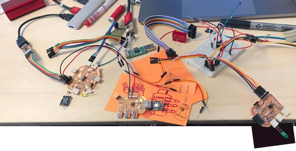
Now I want to test my wiring between the boards, I made it flexible so I could change around the plugs on the motherboard. And I really studied the connectors and which wires would connect to which pin on the board. I connected everything and since there are blinking programs on all three boards I at least found out that the ground and VCC were connected correctly.
The code on our group-page is not complete, the motherboard-part is there, but was altered afterwards, so is not functioning very easily, but the code of the Nodes were on a different computer and were not uploaded.
I have to ask about that if we meet the whole group again. So first get ready for Today's class and later get this working. (while in class I do not have 2 USB-ports free so I am not able to upload with updi and ftdi for power...)
Learnings this week
This week was not my finest. I did officially finish the assignments about input and output and I am happy about that. But I struggled a lot with my networking and I get the feeling that I cannot find the right information with good examples that fit with my amount of knowledge:
- I did not get it working yet.
Wednesday afternoon with Erwin.
Erwin wrote something about fixing the problems we had with the group-assignment and I asked him if he had the code for that uploaded anywhere. He said no, but we could shortly meet in between the regional an global meeting.
Erwin shared his final code with me (with completely different boards having different serial output (hence a serial.write and a serial1.write))
He also gave some explanation of what he did to change things for his set-up.
This was great, because the code was quite clean and simple, but also had some serial.print code in it which was not necessary for me.
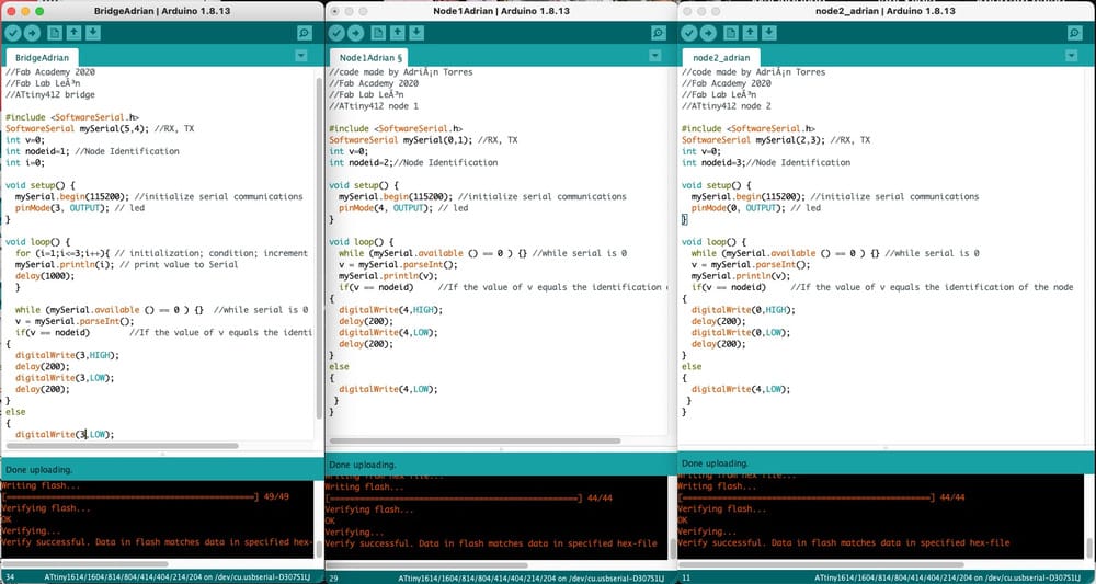
So after some research on his code I could change it so that it would probably work for my boards. and I added some extra LED's so I could see if there was connection and if the loop was running.
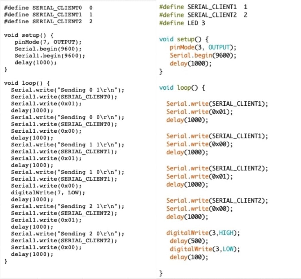
Code Master
 1
 2#define SERIAL_CLIENT1  1
 3#define SERIAL_CLIENT2  2
 4#define LED 3
 5
 6void setup() {
 7   pinMode(3, OUTPUT);
 8   Serial.begin(9600);
 9   delay(1000);
10}
11
12void loop() {
13
14  Serial.write(SERIAL_CLIENT1);
15  Serial.write(0x01);
16  delay(1000);
17
18  Serial.write(SERIAL_CLIENT1);
19  Serial.write(0x00);
20  delay(1000);
21
22  Serial.write(SERIAL_CLIENT2);
23  Serial.write(0x01);
24  delay(1000);
25
26  Serial.write(SERIAL_CLIENT2);
27  Serial.write(0x00);
28  delay(1000);
29
30  digitalWrite(3,HIGH);
31   delay(500);
32   digitalWrite(3,LOW);
33   delay(100);
34
35}
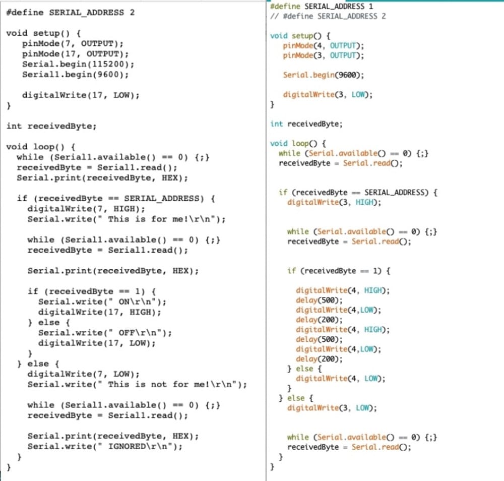
code node
 1#define SERIAL_ADDRESS 1
 2// #define SERIAL_ADDRESS 2
 3
 4void setup() {
 5   pinMode(4, OUTPUT);
 6   pinMode(3, OUTPUT);
 7
 8   Serial.begin(9600);
 9
10   digitalWrite(3, LOW);
11}
12
13int receivedByte;
14
15void loop() {
16  while (Serial.available() == 0) {;}
17  receivedByte = Serial.read();
18
19
20  if (receivedByte == SERIAL_ADDRESS) {
21    digitalWrite(3, HIGH);
22
23
24    while (Serial.available() == 0) {;}
25    receivedByte = Serial.read();
26
27
28    if (receivedByte == 1) {
29
30      digitalWrite(4, HIGH);
31      delay(500);
32      digitalWrite(4,LOW);
33      delay(200);
34      digitalWrite(4, HIGH);
35      delay(500);
36      digitalWrite(4,LOW);
37      delay(200);
38    } else {
39      digitalWrite(4, LOW);
40    }
41  } else {
42    digitalWrite(3, LOW);
43
44
45    while (Serial.available() == 0) {;}
46    receivedByte = Serial.read();
47  }
48}
Wednesdaynight, uploading
I was very afraid to upload this, because If it would not work, I really had no ideas anymore how to fix it.
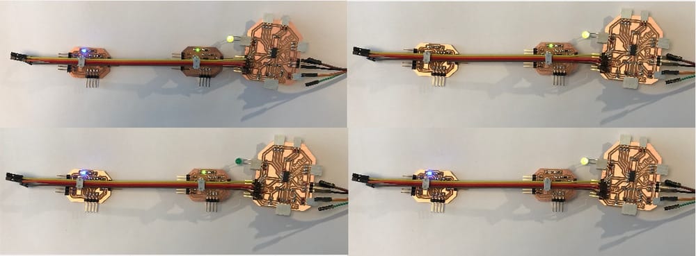
BUt my hard work and rework and rework did work. It uploaded nicely and Yes, everything is blinking according to plan.
Mission accomplished
Extra learnings after this:
-
If I am learning something new, I have to find examples that are clean and a good match with my situation. And because the ATtiny412 is quite new there are not many examples on the site of neil. most of it is made with older microchips. Those examples of the 412 ar also where the writers of the code are also struggling.
-
This is really bad for my learning curve. I get really frustrated and on monday I was thinking of giving up on this thing.
-
Sadly enough so much time was needed (again) to just reach the basic assignment that I don't get to learn more than the bare basics.
Links to Design-files
Here are the links to the designfiles of this week.
The main board:
The nodes: