Week12, Output
This week is all about learning how to connect output devices to a microcontroller. From LED's, charlieplexing, screens (LCD/OLED/E-Ink) and different motors. Last part about artificial muscles was very interesting.
Wednesday Global Class
The different output-devices are showed and shortly introduced how to connect them
Weekly Assignment
In my own words
Group assignment:
- Compare and test the amount of current of different output devices Individual assignments:
- design an output for one of your boards, or design a new board with it.
Planning this week
On thursday we have local instruction and group assignment. On friday I have to work and this week on tuesday it is Kingsday, and I promised my family to go out with our little boat. It is quite a tight schedule this week. I made my planning around this schedule.
| Day | Lesson | subject/activity | activities |
|---|---|---|---|
| Wednesday | global class | make this plan | |
| Thursday | local class examples of the output-devices | group assignment output-current-test | |
| Friday | 'work' for my work | ||
| Saturday | global open time | start on individual assignment | |
| Sunday | work on KiCad-model | family-time | |
| Monday | morning presentation Waag | work for work | afternoon local Fab time |
| Tuesday | Kingsday National Holliday | morning work on individual assignment | |
| Wednesday | presentations | ready to present | fix last things |
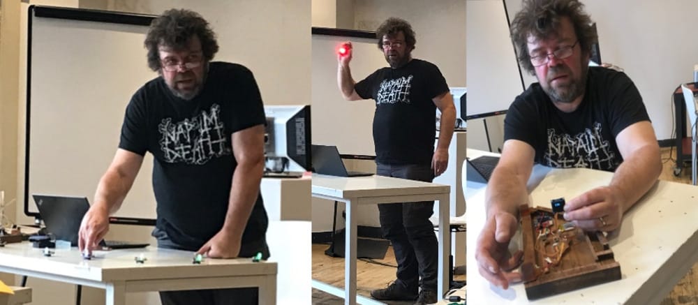
output devices examples
Henk showed us different examples of output devices
 ice-measurement
LED-screens
ice-measurement
LED-screens
Group assignment
For the group assignment we looked at the LED's which Nadieh will use for her final project. We looked at how much energie they would use in different settings.
RGB-LED’s 24 circle 5 volt
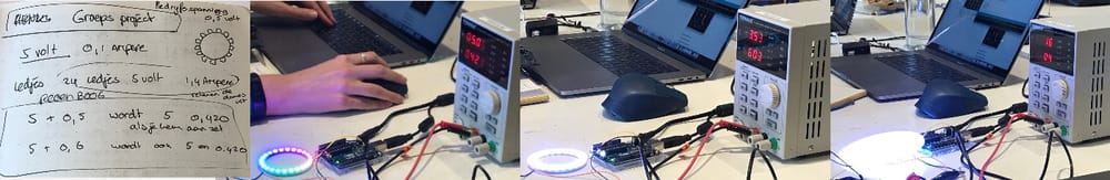
RGB-LED’s 60 per meter 5 volt
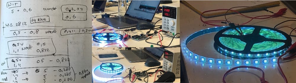
White LED’s 24 volt
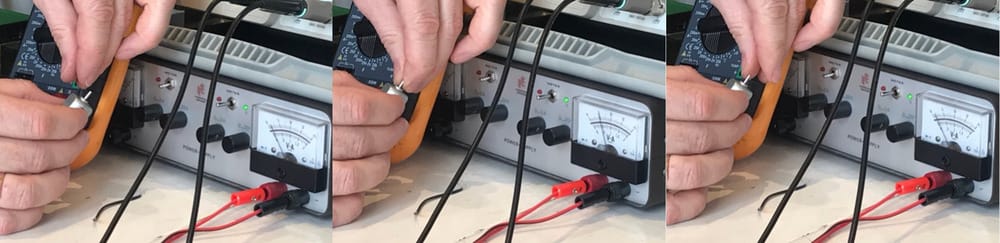
With Erwin and Philip we looked at a few different DC-motors and how to measure the wattage and current. It is really useful to understand how to measure all these things.
DC-motor
Three sizes
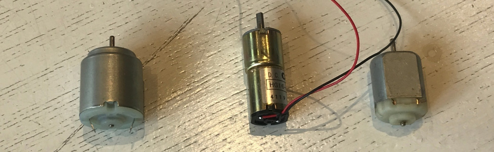 Small ; Small with gearbox ; Large
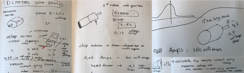 In order to see the difference in current we wanted to put some force on the axis. you can clearly see the difference on the amps.
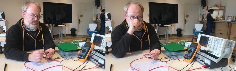
 Erwin tried it a lot of times and hurt himself a little bit 'ouch'.
Learned about current and voltage
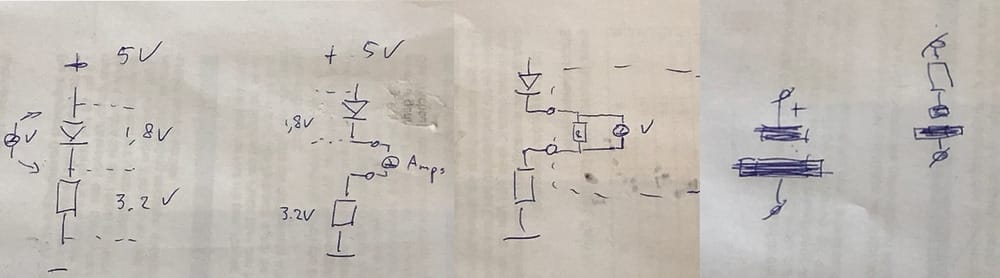
Voltage drop
Current is measured by the voltage drop over a known very small resistor
Individual assignments
Make some output for one of your boards
I will redesign my senslu-board so I can use it for the output.
motors and shields with h-bridges
In the machine-week I was working with different motors and learned a lot already about the H-bridges and connecting external power to the different motors.
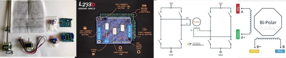 back then I followed some tutorials and found some great simple code to work with motors. To read more about it you can look at the documentation of week 9 on motors
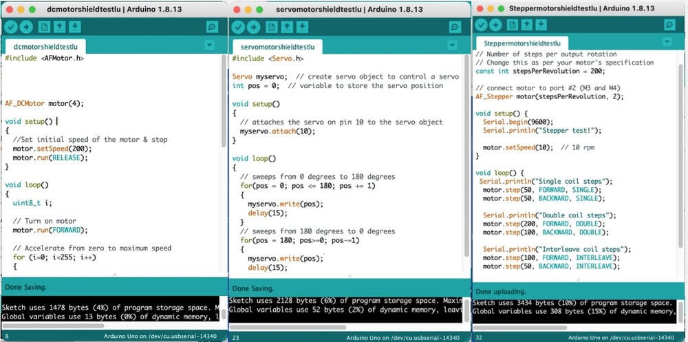
and together with Erwin we got our motors working.
Another subject
I decided to work with charlie-plexing, so I can give output vor my worm-mood-station. I would like to show the different measurements
soft robotics
I was really triggered with the artificial muscle idea, but according to Henk it is too complicated to get it right during only one week. My idea was, that I could make a 'life'-worm so to show how well they are doing inside the bin. When I told about this in the regional meeting Nicolas showed me an example of a student a few years ago ULB-artificialmuscle.
Henk told me that I could maybe look into soft robotics.
Molding casting
New milling job New cast in mold-star-30
Electronics
The hair of my Elvis broke last week and without his hair Elvis is very sad (and not programmable, because it is the UPDI connection). So I milled myself a new Elvis.
Saturday open time
Adrian showed me his soft-robotic example (just the silicone-part, sadly not the motor-part.) It looks wonderful to make a moving object by inflating it with air.
This is perfect for a worm that looks alive and well
Adrians soft robotic project
And I was telling the boys about my charlieplexing-idea and showed them my 8 by 8 pin ledboard that I bought, Rico shared this great example on utube.

Sunday
I looked into soft robotics and found a lot of information, all a bit the same, but when I searched on soft robotic and worm I got really interesting results:
- researchgate; radial expansion soft worm
- instructables on robotic worm
- instructable roboticworm with layers of vinyl
- Uni Berlin pneuflex written tutorial
Especially the last one from the university of berlin has a great tutorial on Youtube

In this tutorial the flexibility and sturdiness of the soft robotics is accomplished by putting sewing thread around the silicone. That makes a great example for my worm, because the look and feel of a worm is exactly that way.
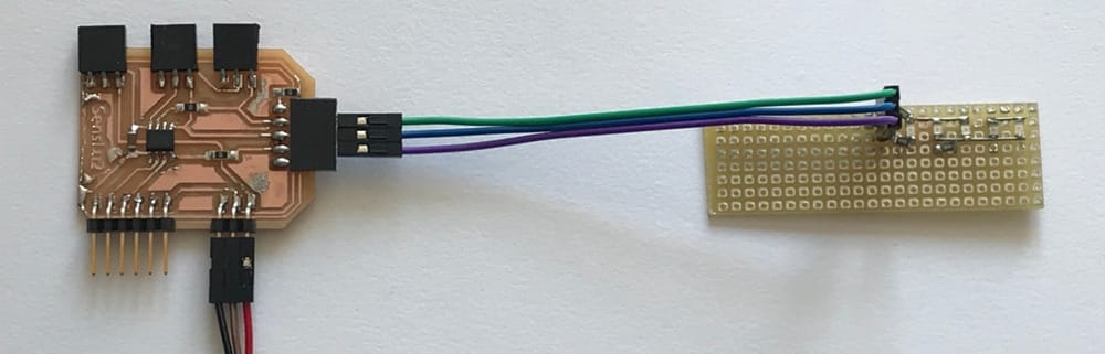
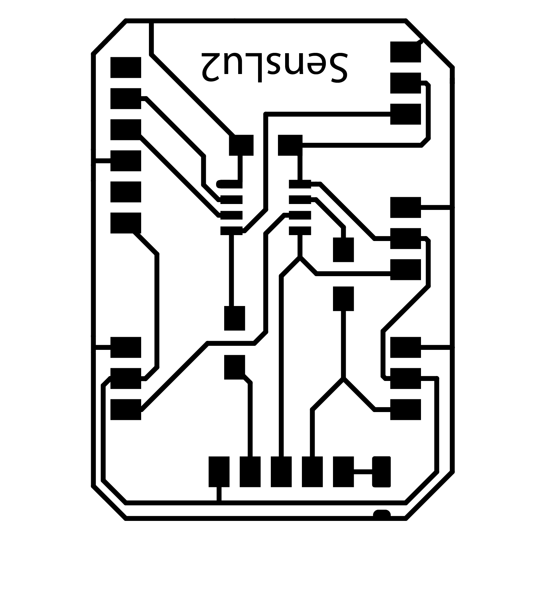
New design for SensLu2
With the right rx and tx pins
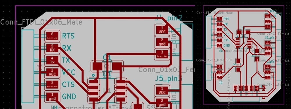
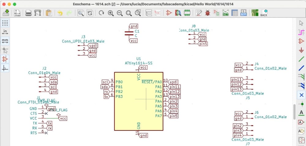
1614 design
New design for a new board with a 1614 with the right rx and tx at once:
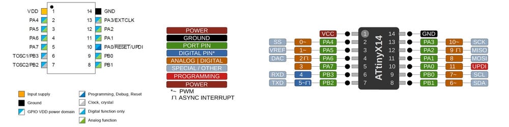 On the side of the VCC de lowest two pins are for:
Tx connected to RB3 the one but lowest
RX connected TB2 lowest pin on the corner
On the side of the VCC de lowest two pins are for:
Tx connected to RB3 the one but lowest
RX connected TB2 lowest pin on the corner
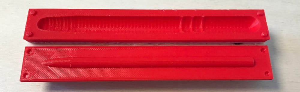
soft robotic worm
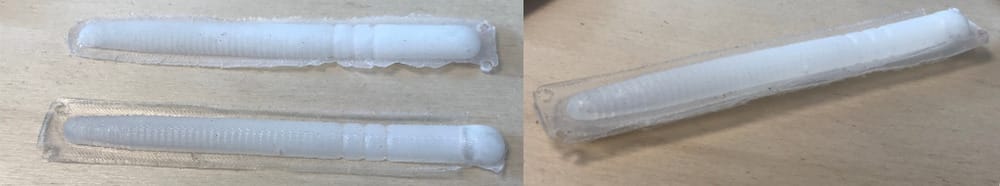
I made a nice design for a 3D-printed mold for my robotic worm. hope fully there is some good flexible
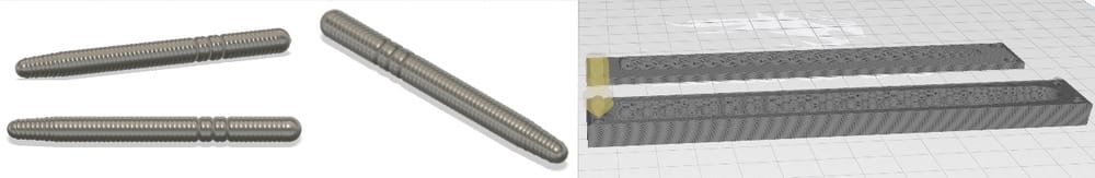 I 3D-printed it here at home and I am all ready to cast my hollow half worms.
Monday Waag-time.
I went to Waag to mill everything. I only had time to mill the senslu2, and barely, because the millingjobs before me took a long time and again the millingbit broke halfway the milling of the traces. I had to redo it, this time I saw that the job was really half done and therefore I chose to do the second try in reverse direction, a good choice, because I could halfway stop the milling and save time.
Gas Sensors
Little research on gas-sensors and what would be useful for my final project
Sensors
- Mq1 niks
- Mq2 smoke flamable gas
- Mq3 alcohol
- Mq4 methane
- Mq5 lpg natural gas carbon
- Mq6 lpg isobutane propane
- Mq7 carbonmonoxyde
- Mq8 hydrogen
- Mq9 lpg koolmonoxide methaan
- Mq135 alcohol benzine ammonia
At Waag we only have mq4 and mq9 laying around and I will try out the mq9
soft robotic worm
There is no soft silicone at the Waag, but I decided to give it a try anyway with what we have. which is KX-Flex 60. it has a pottime of only 2,5 minutes so I had to be quick.
With a good covering with the smooth-on it worked fine.
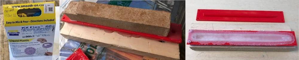 The second try, without re-smooth-onning it did not work out. it was all tacky and awful.
Monday/tuesday at home
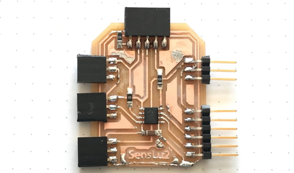
Soldering the Senslu2
My pcb for the Senslu2 came out a little crooked, one end was milled off and therefor I lost my vcc-line at one side. I fixed it with coppertape and extra solder, but it does not look very professional. At the moment the connection is restored but I hope it will stay okay.
 I soldered my LuSens2 and when I wanted to connect it to my updi... the updi made no connection with the laptop. So I did not have a port to send things through
Charlieplexing the leds
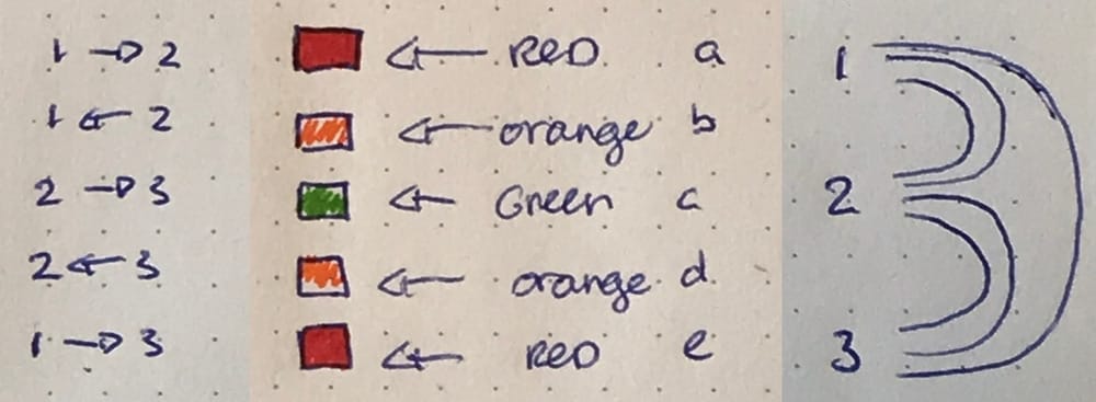
First I made some sketches for my LED-worm-checker. If I think spirally, the most basic way of telling the worms habitat values would be with trafficlight-coloured LED’s. I could make a three-LED-signal for the different values. But it could be that the value has to be ‘not too high’ and ‘not too low’ (for example temperature, humidity, Ph-value) so for this week I want to make a charlieplexed LED-output with 5 LED’s. Green in the middle and then orange under and above the green and red below and above the orange.
With a simple Charlie-plexing tutorial I found that for 6 LED’s I need 3 pins. Good, because I can do that with my LuSens-board.
So I made some sketches.
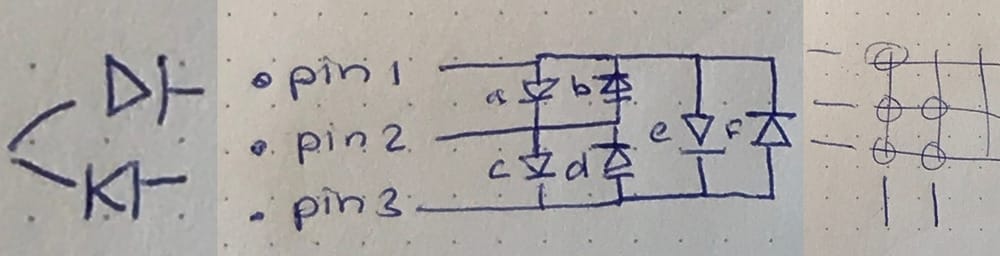 After I understood the way it should work I made some sketches how my own 5-LED-trafficlight should look
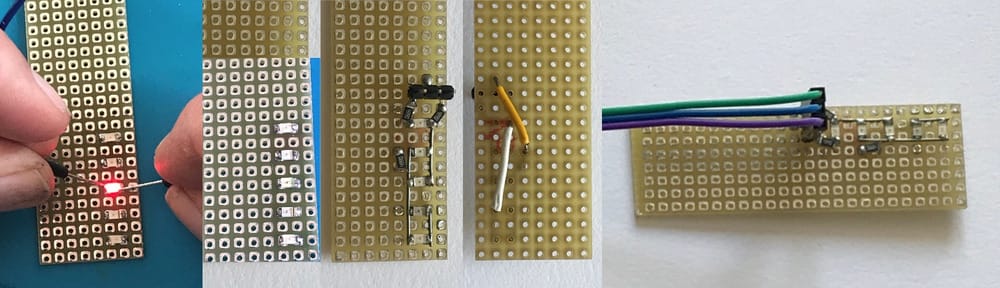
 and just started soldering on a development-board.
I decided to first put the Leds on the board. and after testing it I found that my green LED's were in fact red. luckily I did have a green led from my electronics design week and I switched the LED's
That was really new, because it is quite hard to connect 2 things to the same point. But I managed. Nice is that because the holes are through the board it is easy to make jumpers at the back to connect the right parts. I wanted to add 100 or 200 ohm resistors at the 3 pins but did not have them so I chose 499ohm making it 1k in total. A bit much, but well the leds are for measurement, not for lighting up the night.
Debugging the UPDI
For that problem I have different solutions. I tried them all:
- I tried different USB-cables.
- I looked at Adrian’s FTDI-UPDI- converter and rebuild that on a breadboard.
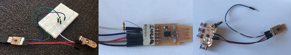
- It did not work so I tried rewiring it without the breadboard. No succes.
- I made some solder on the USB connection of my updi. For better connection
- I measured the connection of my usb-cable with the updi
- I resoldered my old UPDI (which earlier did show up on the laptop but would not connect to the attiny.) nope
- I checked all the connections on the (previously working UPDI) but could not find a misding connection or a short anywhere. Noting worked.
Arduino instead
I decided to connect my new output-ledboard to my arduino. I found a nice Tutorial on the arduino site with the charlieplexingcode for 6 LED’s and 3 pins.
  1int A = 2;
  2int B = 3;
  3int C = 4;
  4
  5void setup()
  6{
  7  pinMode(A, OUTPUT);
  8  pinMode(B, OUTPUT);
  9  pinMode(C, OUTPUT);
 10
 11}
 12
 13
 14/*
 15* Turn on the given LED
 16*
 17* @paramledNum LED to turn on (1..6)
 18*
 19*/
 20void setLED(int ledNum)
 21{
 22	if(ledNum == 1)
 23	{
 24                pinMode(A, OUTPUT);
 25                pinMode(B, INPUT);  // changed to input to trigger tri state.
 26                pinMode(C, OUTPUT);
 27
 28                digitalWrite(A, HIGH);
 29                digitalWrite(C, LOW);
 30	}
 31
 32	if(ledNum == 2)
 33	{
 34                pinMode(A, OUTPUT);
 35                pinMode(B, INPUT);
 36                pinMode(C, OUTPUT);
 37
 38                digitalWrite(A, LOW);
 39                digitalWrite(C, HIGH);
 40	}
 41
 42	if(ledNum == 3)
 43	{
 44                pinMode(A, OUTPUT);
 45                pinMode(B, OUTPUT);
 46                pinMode(C, INPUT);
 47
 48                 digitalWrite(A, HIGH);
 49                 digitalWrite(B, LOW);
 50	}
 51
 52	if(ledNum == 4)
 53	{
 54                pinMode(A, OUTPUT);
 55                pinMode(B, OUTPUT);
 56                pinMode(C, INPUT);
 57
 58                digitalWrite(A, LOW);
 59                digitalWrite(B,HIGH);
 60	}
 61
 62	if(ledNum == 5)
 63	{
 64
 65                pinMode(A, INPUT);
 66                pinMode(B, OUTPUT);
 67                pinMode(C, OUTPUT);
 68
 69                digitalWrite(B, HIGH);
 70                digitalWrite(C, LOW);
 71	}
 72
 73	if(ledNum == 6)
 74	{
 75
 76                pinMode(A, INPUT);
 77                pinMode(B, OUTPUT);
 78                pinMode(C, OUTPUT);
 79
 80                digitalWrite(B, LOW);
 81                digitalWrite(C, HIGH);
 82	}
 83}
 84
 85void loop()
 86{
 87	for(;;)
 88	{
 89		setLED(1);
 90		delay(500);
 91		setLED(2);
 92		delay(500);
 93		setLED(3);
 94		delay(500);
 95		setLED(4);
 96		delay(500);
 97		setLED(5);
 98		delay(500);
 99		setLED(6);
100		delay(500);
101	}
102}
but the leds went on and of in a weird sequence and sometimes it flickered really weird with two leds at the same time.
Hmmm, hoe to tackle this one. I decided to make the same 5led setup on a breadboard to easily try some different settings. To be sure that the 6th led would not interfere with anything I took an extra white led for that one.
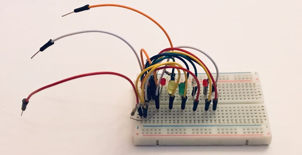 The flickering part was probably the 6th led, because now it would nicely turn on and off the different led’s, but still in a weird order.
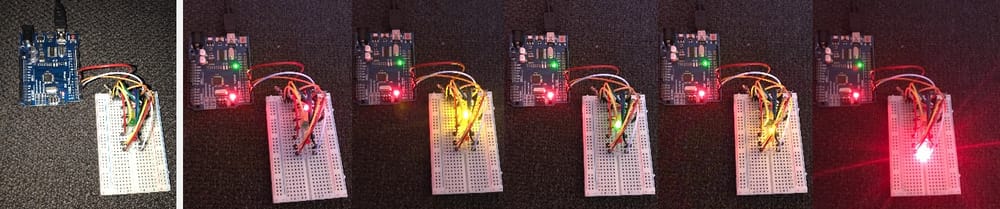 Then I found that if I switched the pin-wires to different pins there would be a change in the order and at the third tryI found an order that looked better. Although it was going the other direction than I expected and still starting at the 2nd LED.
Succes
I looked at the code and found that although the code started nicely with pin A pin B and pin C. It changed the order of what pin would be on or off or on input in a totally random order. I changed the loop-part of the code and gave it little comments (in dutch) for me to understand it.
 1 for(;;)
 2  {
 3    setLED(6); // middelgroen
 4    delay(2000);
 5    setLED(5); // snoeroranje
 6    delay(500);
 7    setLED(3); // snoerrood
 8    delay(500);
 9    /*
10    setLED(4);
11    delay(500);
12  */
13    setLED(5); // snoeroranje
14    delay(500);
15    setLED(6); // middelgroen
16    delay(2000);
17    setLED(1); // wegvansnoeroranje
18    delay(500);
19    setLED(2); // wegvansnoerrood
20    delay(500);
21    setLED(1); // wegvansnoeroranje
22    delay(500);
23  }
24
25
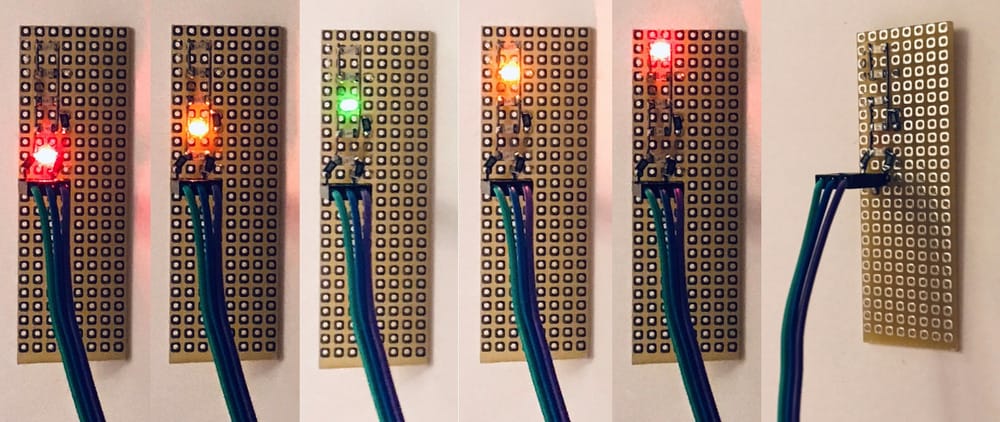 With some playing around I got my LED’s to work in a way that looks like my sensor-output.
Only sad thing is that I cannot have a sensor-input on the same attiny412. So I’ll have to upgrade to a 1614 anyway. Lucky for me I have the design ready to mill.
my not finished moving worms
I have two reasonable half worms to work with. So still growing strong.
 I have wound the polyester thread around the worm, and I really like the look. At Waag I'll continue on finishing the worm and make it airtight.
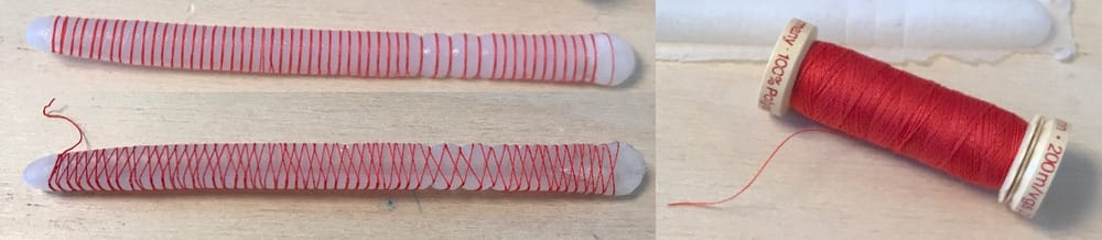 I never finished this side-project, because the rubber casting I used was way to stiff and we did not have the right kind of rubber at Waag, I would need dragonskin or ecoflex 30 which is a lot more flexible. I will try and get that, some day. But for now, the extra worm-project stops here.
Learnings this week
Making a better board with all the possibilities to output something has helped me a lot, this way I also solved the input-week.
- I am finally getting grip on the Attiny and the RX and TX. I still think it would be good to have a real good tutorial on that.
- I think it is a pitty that I am in fact working on the fixing the previous assignments and therefor not really able to dive into the subject of this week.
- I think it is quite complicated that we work with newer attiny412 and large chips and most of the examples are with older chips.
- I did get my LED's to work so I am happy about that result.
- The extra bit with my worms has to be continued, we don't have the right material and don't have the motors/connections to make that.
Links to Design-files
here are the links to the designfiles of this week: This week I worked on a new board with the TX and RX at the right place:
And as an extra I made a mold for soft robotics: