Week 14
Networking and Communications
Group assignment Send a message between two projects
Individual assignment Design, build, and connect wired or wireless node(s) with network or bus addresses
Group assignment
 - Send a message between two projects
 - understand UART and I2C
 - find tutorials on the different communication ways
 - figure out which one works best for my end project.
We did the group assignment all together this time, so most of the detailed information you can find on the group page but the highlights and what i got from it i will explain here.
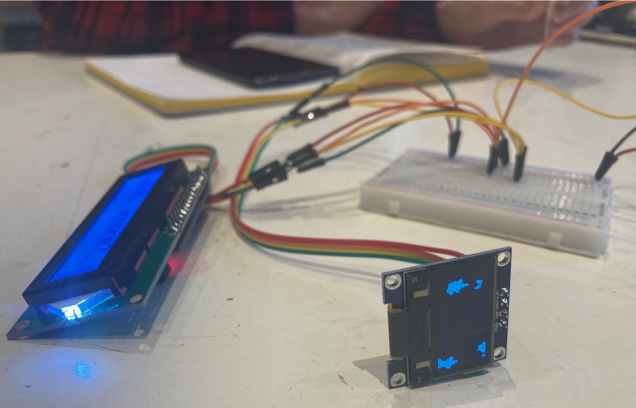
I2C network
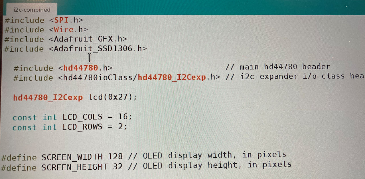
We used an Arduino to set up a basic connection with an LCD and an OLED connected through the SDA (data) and SLC (clock)
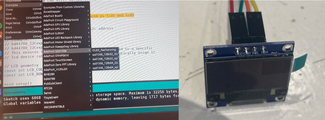
 Library for the LCD:

Library for the OLED:
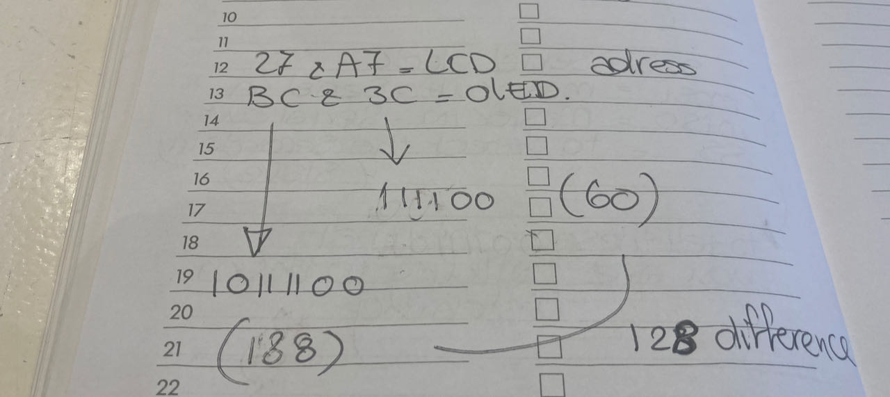
When trying to find the addresses something strange was happening, we got 4… but Erwin quickly realized his “mistake” he made the Arduino search for 256 addresses and since there are only 128, so we bumped into them twice. Below my calculation while trying to understand what was happening.
to be able to control them both we hade to merge the 2 files so Erwin copied the Adafruit library in the other file.
The full code you can find on the group page many thanks to Erwin for helping to understand this.
UART communication
We connected 2 board with their RX and TX to the Arduino and also the GND and VCC.
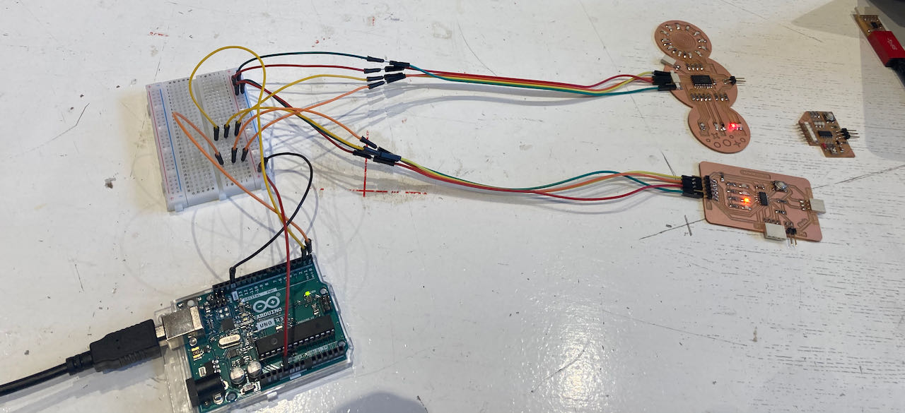
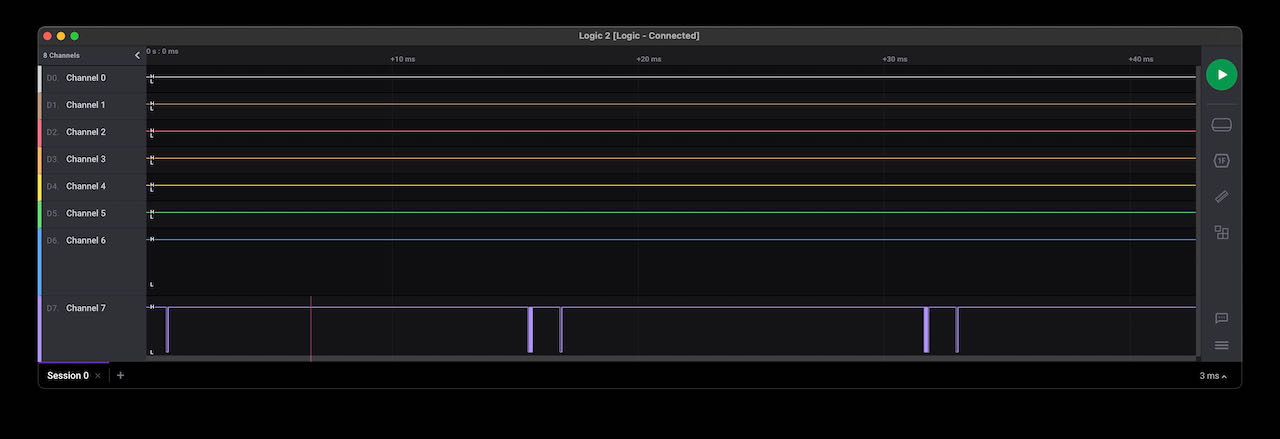
To be able to see what was happening we connected a logic analyser to the TX from the Arduino that should receive data.
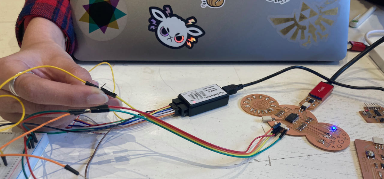
Which it did:
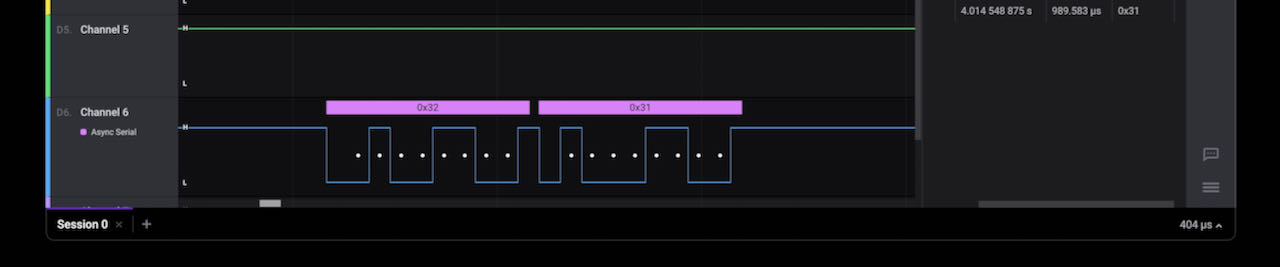
Strangely enough it was getting the wrong address, 31 instead of 1, we tried to solve this in many way, makes the data heximal (HEX) or Binary (BIN) but nothing seemed to help so.. we decided to rename the boards in their own programme (done by Nadieh) to the names the arduino IDE was sending out.
After the fun practical group assignment I was still a bit lost in the theory so decided to watch the very elaborated YouTube video of Daniele explaining networking. Which I will try to scribble down here in what we call in Dutch “Jip en Janneke taal”
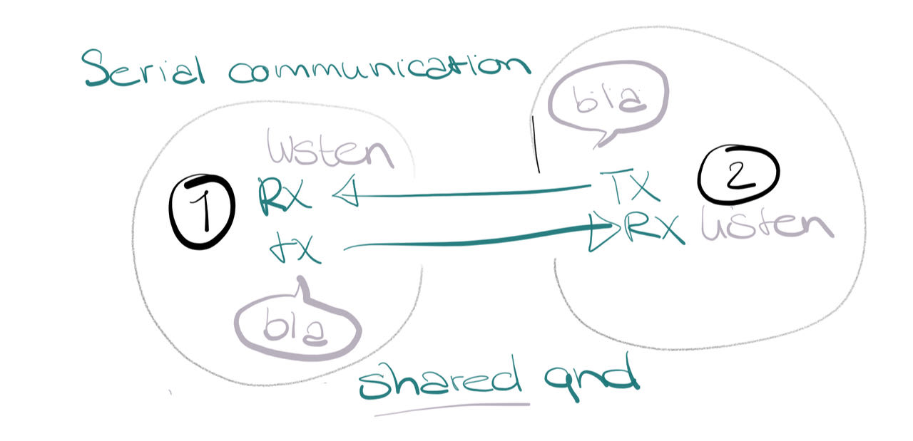
Serial communication UART is a 2 way street, but with one lane, everybody talks the whole time so it can get messy if to many thing need to be communicated, very fine for simple things. Works with RX and TX.
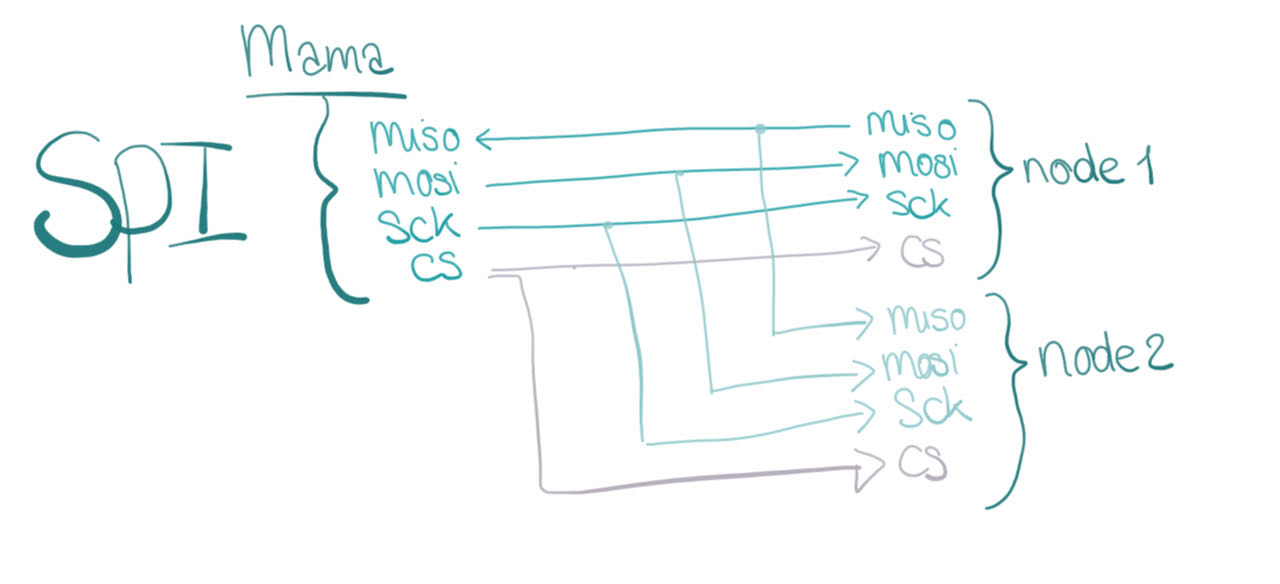
SPI Serial communication with clockdata. It feels like a checklist, the hoist calls out a specific name, this one listen on the speed of the same clock for a bit of time till the door is closed and the hoist calls another (or the same) name. For this way of communication you need an extra pin which is called SS and this one functions as the address of the node. The other 2 pins are calles MISO and MOSI plus the serial clock (SCK)
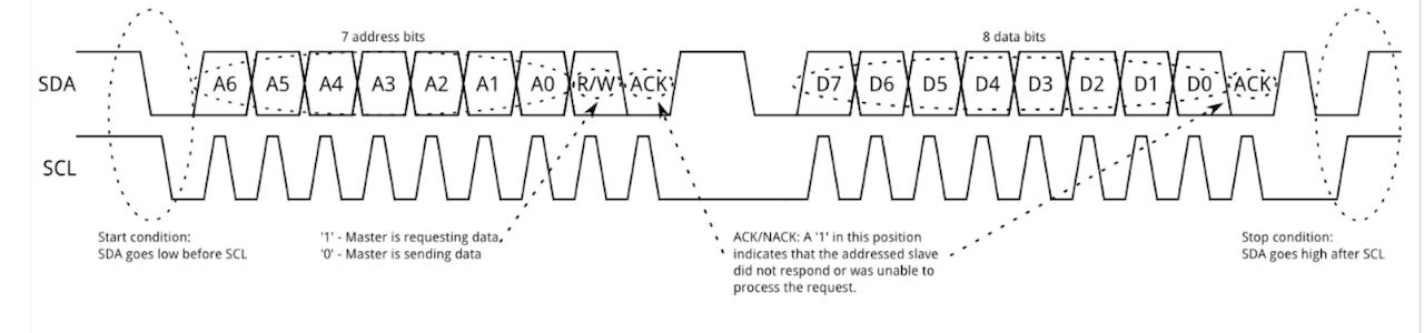
 I2C is like a train, it passes all the stations with the same info and the people that recognize their station name get the message. You need to find the addresses off the nodes… This works with the SDA and SCL pins from your microprocessor.
Individual assignment
- Design, build, and connect wired or wireless node(s) with network or bus addresses
- try to connect the “reading” sensor within a network to an output
- Figure out how to make my own KY033
- make it work
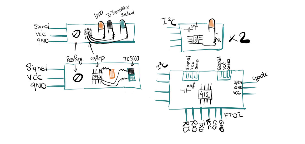
I wanna try to make a sensor that will detect my pills in their box to decide to try to make my “own” KY 033 and for it to work with this weeks assignment i will create a mama board with 2 nodes which i will connect with either Uart (RX/TX) or I2C, i have both the connections on my mama and nodes with LED board.
Here is some information that explains very well how the IRsensor board works which i found on maxembedded
The KY033 i tested out with an Arduino at the lab, with this code:
int WhiteLed = 2;
int Sensor = A5;
int sensorValue = 0;

void setup () {
  pinMode (WhiteLed, OUTPUT);
  Serial.begin (9600);
}
void loop () {
  sensorValue = analogRead (Sensor);
  if (sensorValue < 50&& sensorValue < 500)
  {
  digitalWrite (WhiteLed, HIGH);
  Serial.println (sensorValue, DEC);
  }
  else (sensorValue > 500&& sensorValue > 1023);
  {
  digitalWrite (WhiteLed, LOW);
  Serial.println (sensorValue, DEC);
  }
}
It looks like it’s doing exactly what i need, detect when there is something that is not black, also in the dark. So as long as i keep the box of my pills black on the inside and don’t switch to NORIT i should be fine.
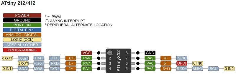
This week it’s again ATtiny412 week, nice and small.
Components of the KY033
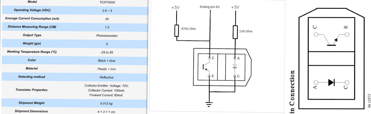
The TCRT5000 is a very compact component with an IRLED and IR photodiode on there. There is a lot of information out there, done here are the most important ones i found online:
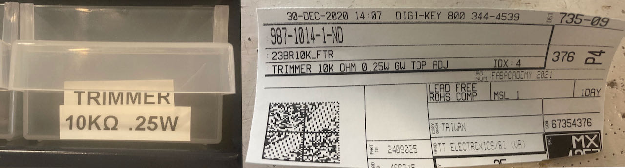
Also there is a trimmer on the KY033 which Henk found for me in the wall of components.
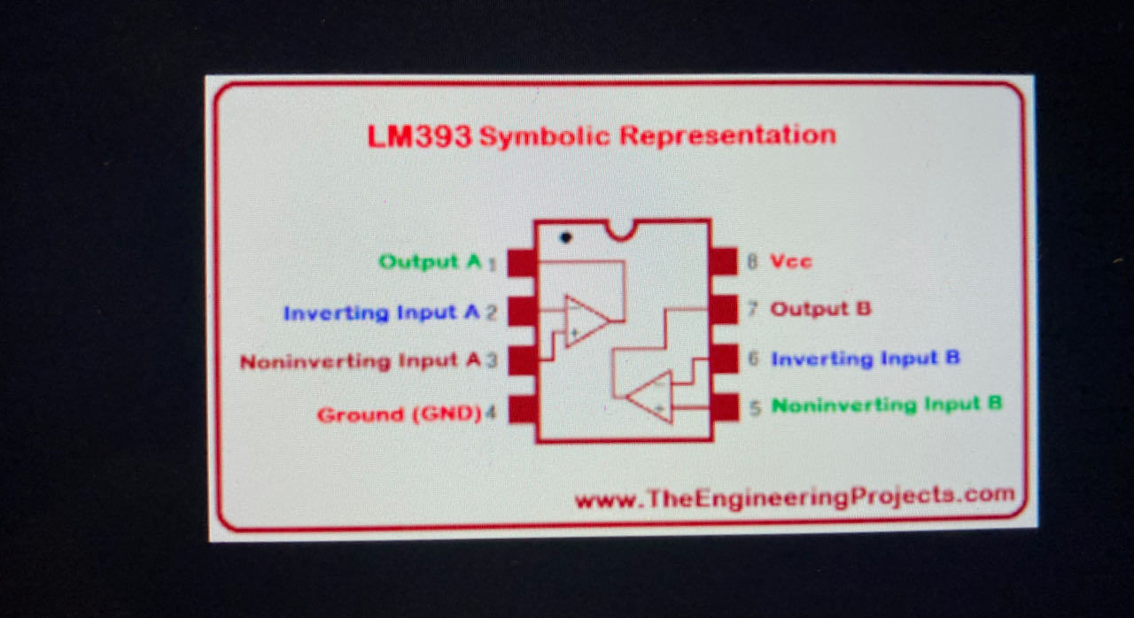
and an LM393 is a dual independent accuracy voltage integrated circuit operated with single or else split supply. These ICs comprises two independent voltage comparators to operate from an only power supply more than a wide variety of voltages. which is not in the FABlab inventory, but i could try to find them somewhere, for now i will just take them of an original KY033.
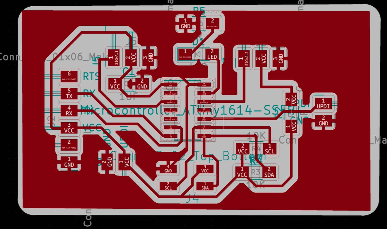
Kicad
First things first, double checked again the board setup after the connected traces under the Atiny1614 from last week, you have to do this in every project you have.

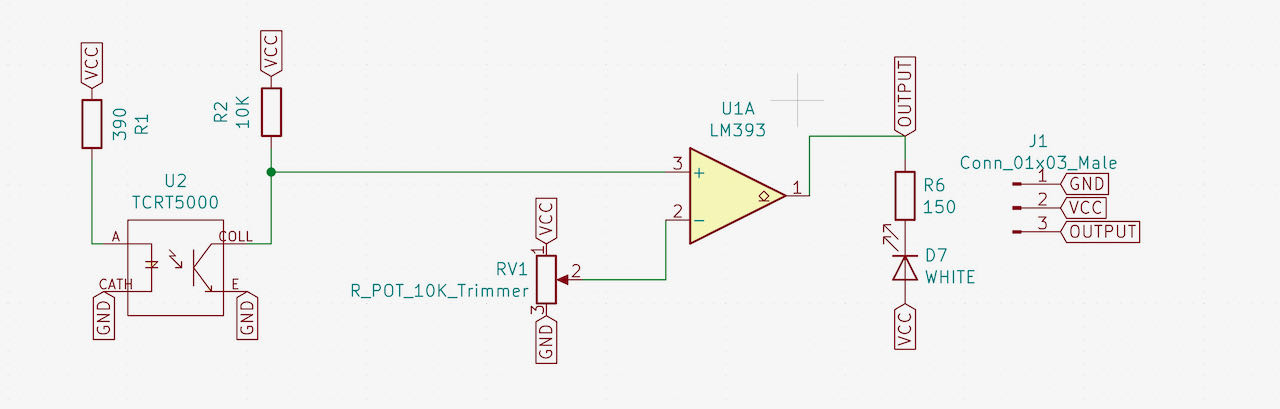
KY033 wannabee
TCRT5000 board
This was my first version which i completed all the way till outlines till the question marks came in my head.
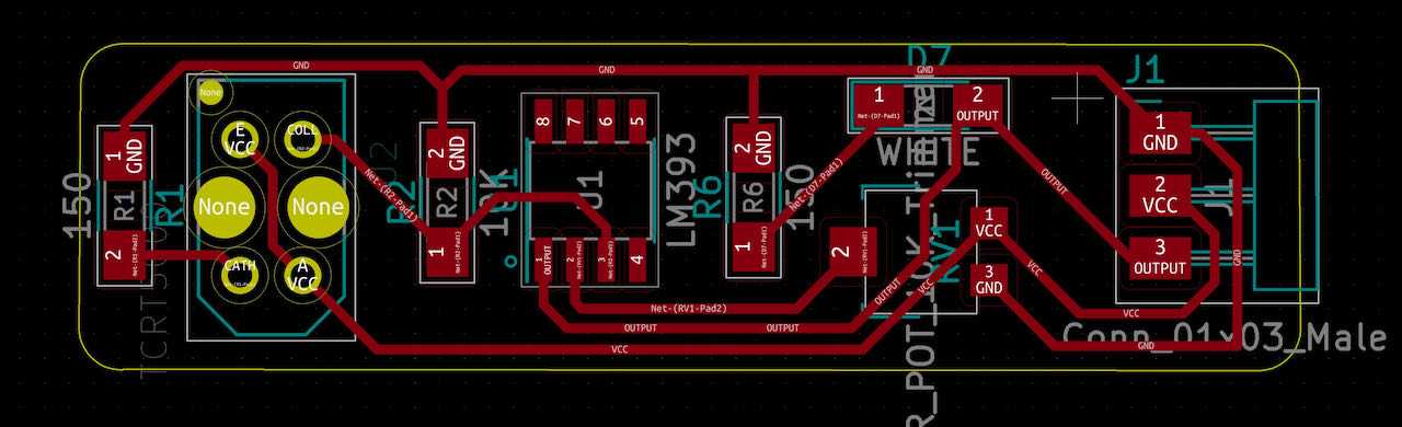
I have some serious doubts on how to connect the TCRT5000, i get different information online, i tried to approach it the same way as the “make you own LED version” which was a mistake
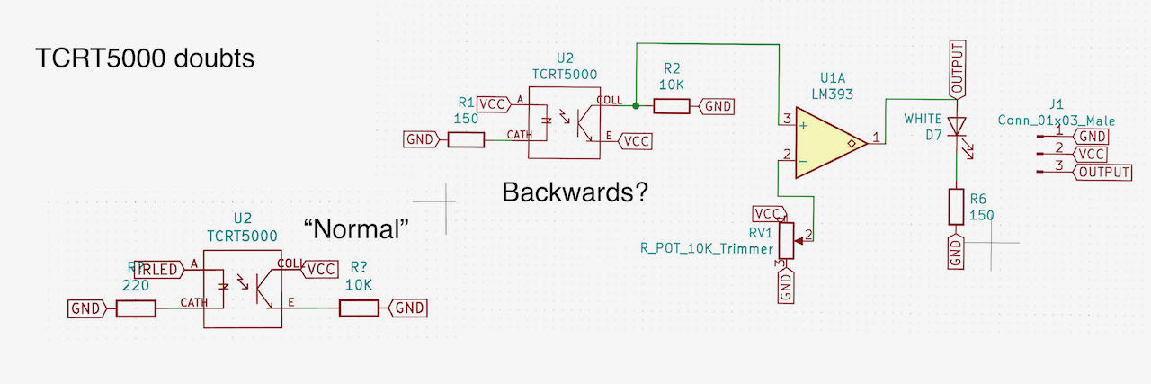
After seeing reading this great KY033 site and this this Youtube video and also researching even more online i realized i made the wrong assumptions how to connect the pins of the TCRT5000 or at least i think.. [this site] really help me to figure it out.
So i remade the TCRT5000board.
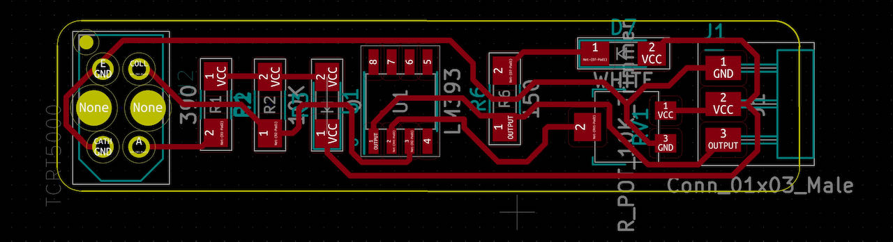
Was only able to mill it this week, so to be continued.
PinLed version
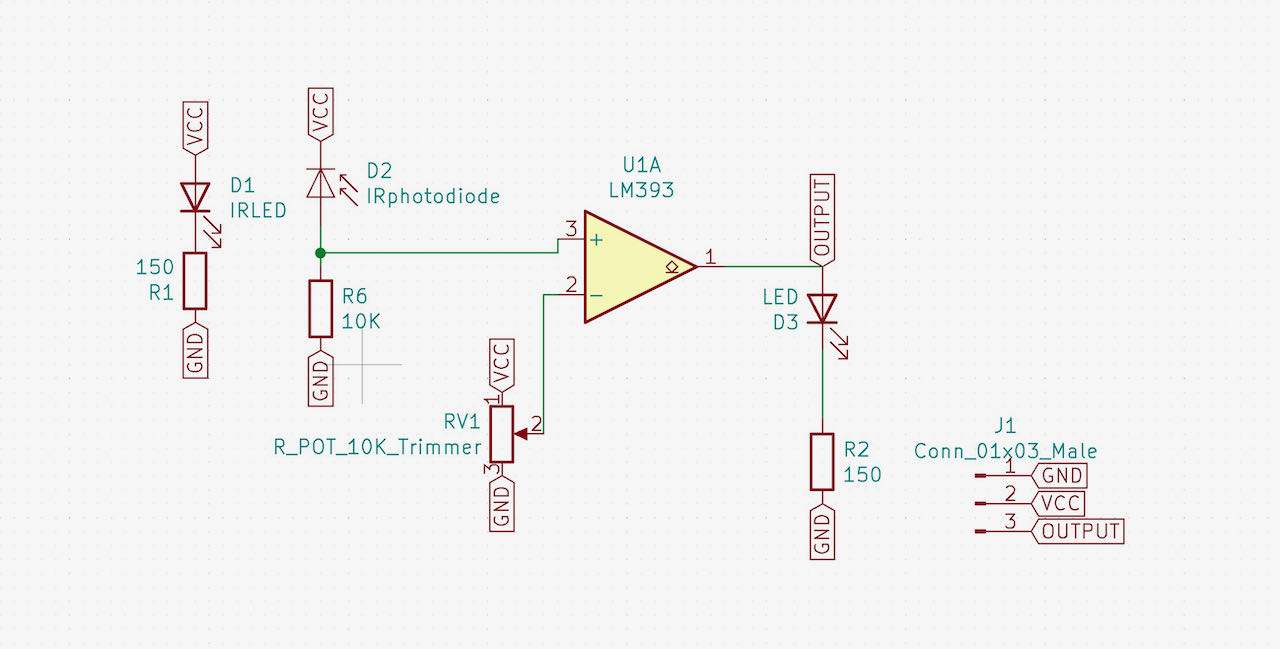
Luckily for me there is a MaxEmbedded tutorial for the separate ledversion although it may have confused me for my KY033 with TCRT5000, for the pinled version it seemed very straightforward.
Had to dig a bit to find the LED pin footprints but loaded the kicad library for it.
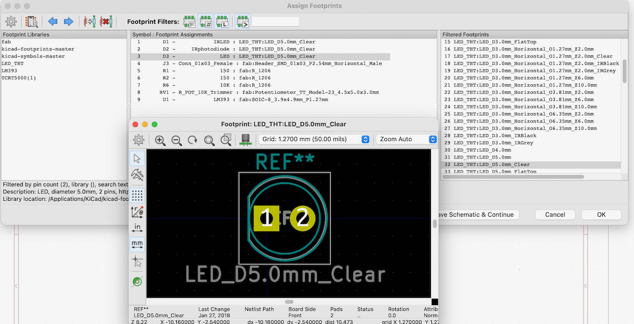
The first version of the IR pinled version. Strangely enough the Photodiode has to be connected the ‘wrong’ way around. Why is still a bit of a puzzle to me…
Here is how they explain it on the Maxembbed site:
- If the IR LED emissions become incident on the photo diode, the photo diode’s resistance comes down to a finite value. The drop across the 10K series resistor is what we use as the input, which is compared with the threshold. The point to be noted here is that more the incident radiation on the photo diode, less will be the drop across it, and hence more will be the drop across the series resistor. If the voltage developed across the resistor is greater than the threshold set by us, the output of the IC will be high, else it will be low. Hence, if our reflected radiation is never strong enough to be greater than the threshold and we have a constant low as output, we can reduce the threshold voltage by turning the “minus shaped” slit in the variable resistance towards its terminal where we connected Gnd. In case our threshold is very low and the output is always high in spite of no radiation or if it is just too sensitive, then you can increase the threshold by turning the slit the other way. When the emissions are absorbed by a black surface, the resistance of the photo diode becomes very high due to no incidence of IR emissions on it, and the output remains low.
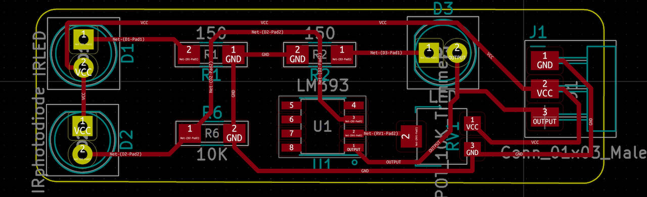
Also made a copper GND fill version for this one.
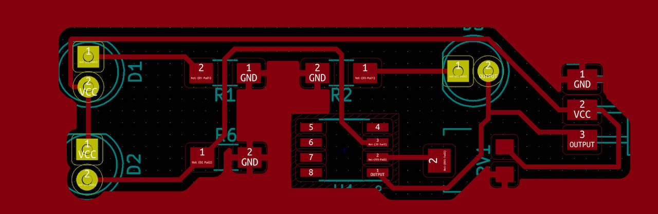
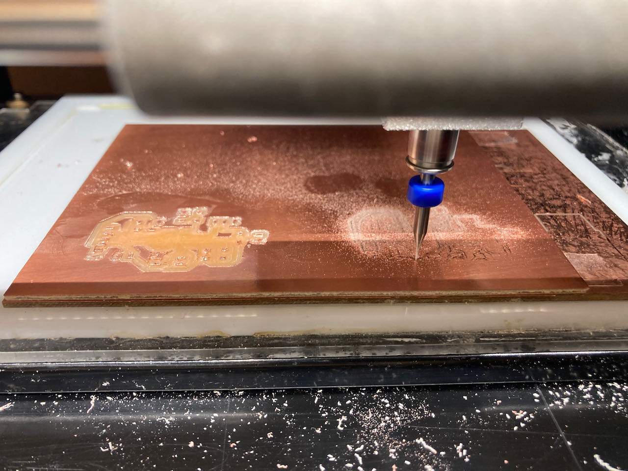
When i was milling the traces came out not deep enough on one side so Henk advised me to push a bit on the plate when fastening the mill to go just a fraction deeper, which worked :)
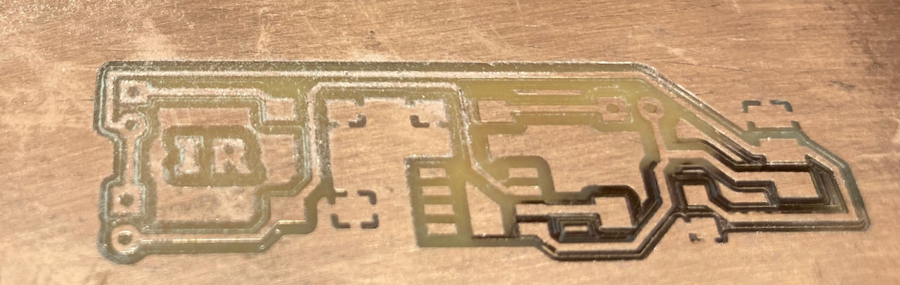
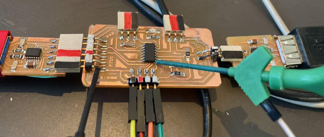
Mama board
Version one .. before the global time
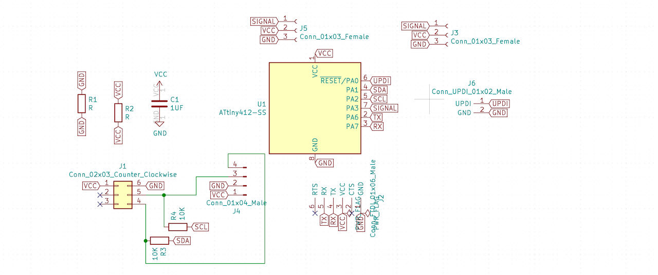
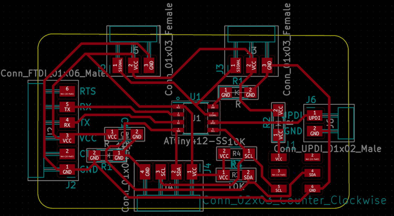
I shared my schematic because i was uncertain which standard there was for plugs and different numeric connection, which was explained by Rico that’s basically there is none, just within your own project keep the same standard and try to keep the VCC and GND far away from each other. I am happy i joint open time since they pointed out a mistake in my original design.
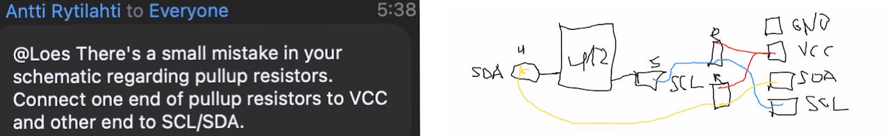
The resistors at the SCL and SDA should actually go to VCC on the other side.. not to them self as i did.. thanks so much also to the beautiful artist who made this drawing but i will not mention his name :)
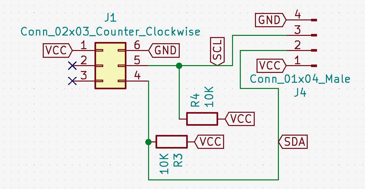
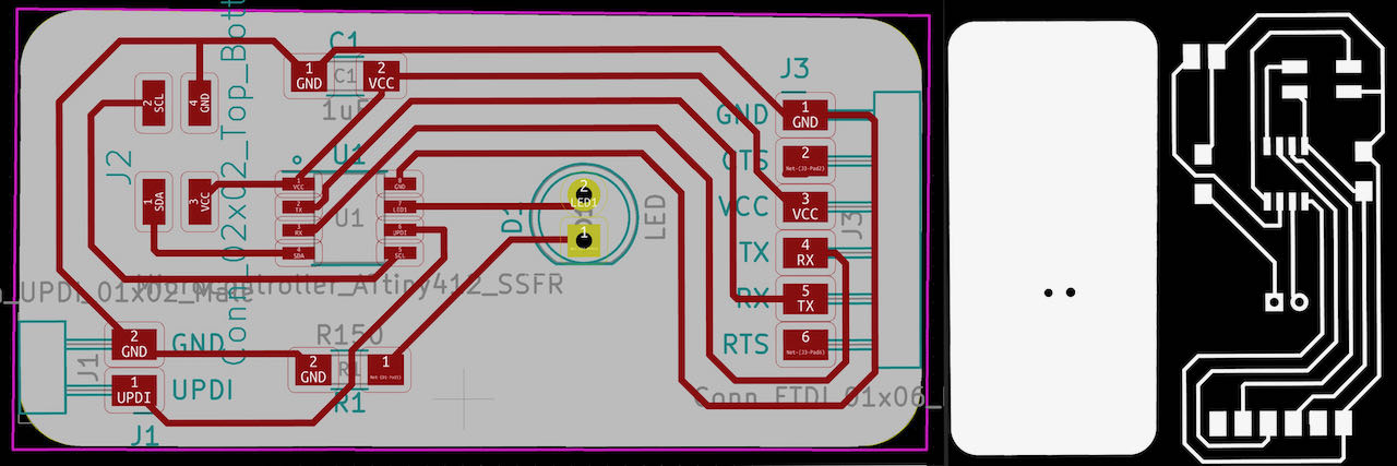
So here she is in full glory with 2 different way to connect my I2C connections and also the possibility with the RX and TX to make a “simple” UART network. (disclaimer: i changed the layout later that day)
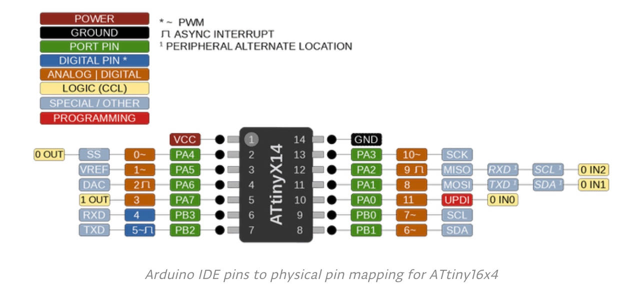
When i arrived at the Waag and shared it with a fellow student we realized having 2 connections is useless when i have only 1 pin available so decided to go for the ATtiny 1614 (pinout below) and while i am on it trow a little LED in the game just for fun (and handy to check the basic connection/programming with).
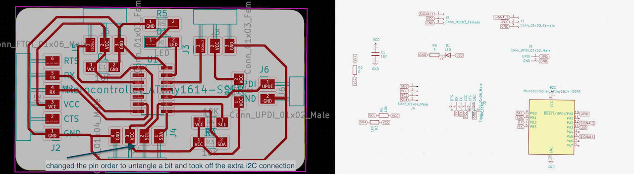
While i was remaking the board anyways i also kicked out the 6 pin connection that was just there making it harder instead of the easier what i intended it for.
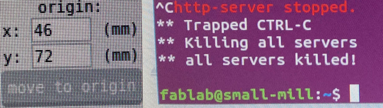
The traces milled like butter with a new 0.4mm milling bit but when i started the outline i got the Motorola screaming at me when it lots the mill from its collid.. which also happened to Nadieh just before me. Now we are both very aware to make sure to tighten both of the screws on the collid, strangely enough this never happened to both of us before.
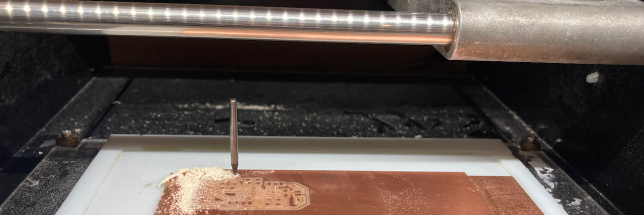
Maybe it was the stress or the machine was a bit off but from that moment there were some mistakes/errors on top of each other, we had to restart the computer and the motorola to make the machine go to the right zero point..
with CTRL C in terminal you stop the mods connection and then i was a matter of restarting, was happy i made a picture of the origin so i was able to restart the process.
LED nodes
The little led nodes boards where nice and easy to make, the through hole gave me a bit of Kicad struggle but ended up just adding 2 circles on top of the holes in the EdgeCuts layer. There must be a more exact way to do this.
The first version that didn’t have copper GND fill
When i filled this one i miscalculated 2 mm which resulted in the edge being cut of an having to make 2 bypasses, one for the UPDI traces and one GND trace.
This made me even more interested in pouring the GND, the process of making a ground copper pour is fairly simply.
Pouring GND
In kicad make a keep out area around the Microcontroller with the “forbidden entry” icon on the right. When you finished with this select the icon above it with a green circle and trace.
- Select F CU - GND
- fill in the
0.8 clearance-0.4 minimum width
The outline of the board is now hidden under the copper but there are 3 icons on the right which give you different views.
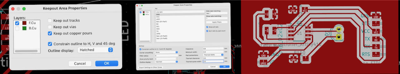
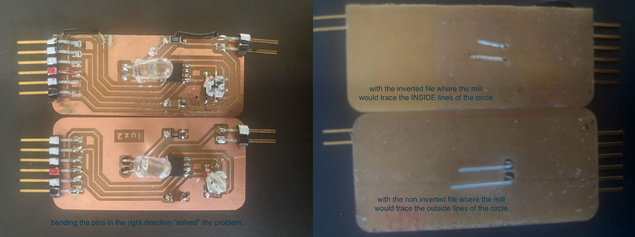
To be able to have the tiny hole i wanted for my pin trough holes i need to cheat a bit and tell the machine the milling bit is only 0.7 wide otherwise mods would skip them.

I tried out both versions, inverted or not and it seems that the not inverted file works the best, it cuts on the black side so if you make little black circles in a white back ground you have the right size holes.
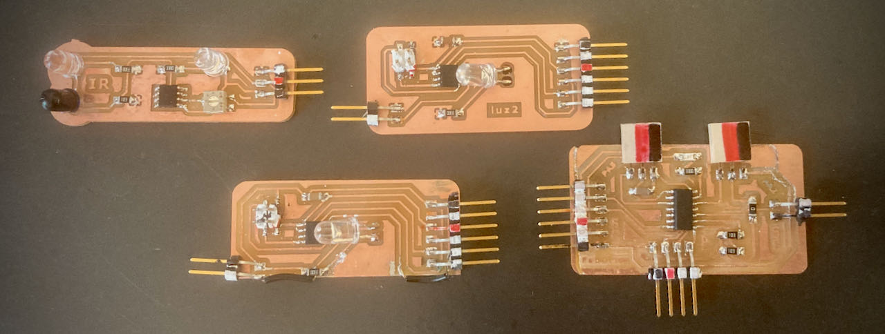
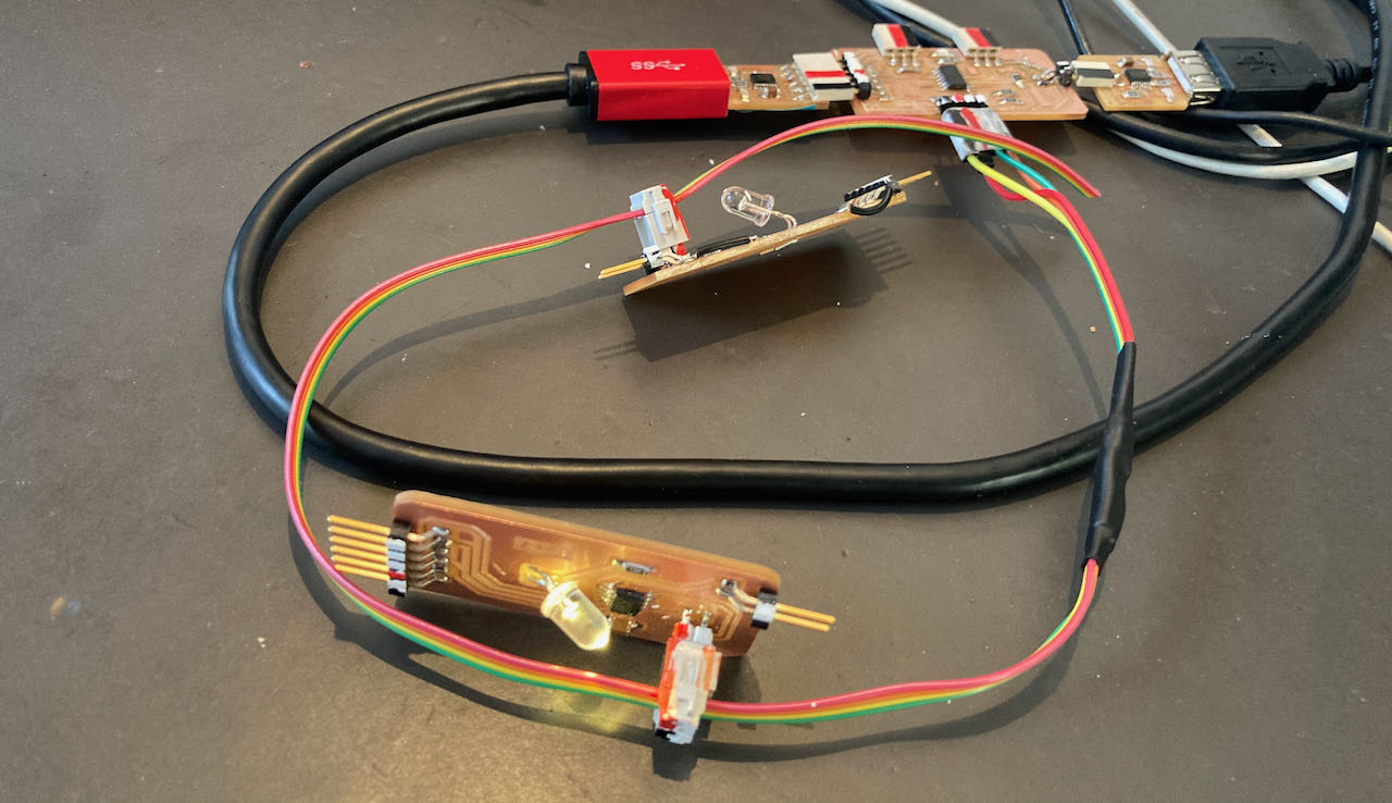
Here is a family picture (the last IR with the TCRT5000 i still have to solder)
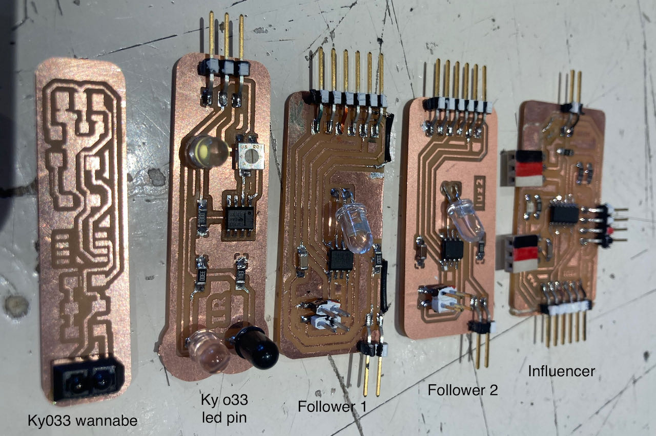
Both working and able to blink, but this is just running on their own chips
Programming UART (tx and rx)
This was how i ended up next week, connections were there but no data flowing.
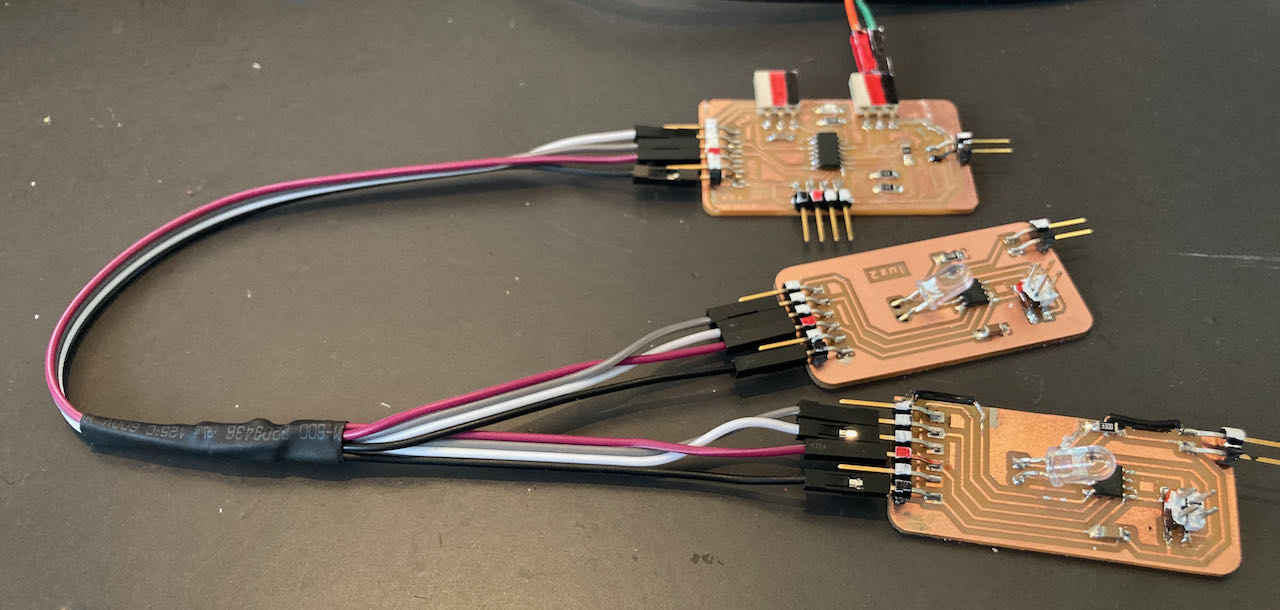
So back to programming, by now everybody from my group was able to finish the week so i could use their docu as guide line to get me through. Since i knew that Lucia also was struggling a bit last week to find a understandable code i figured i peek at her page to see what she did, thanks for being so clear in you documentation Lucia, it helped me a lot.
After connection the wires, the tx and rx of course had to be switched at my mama board and then everything was fast and easy.
Programming the Nodes UART
//#define SERIAL_ADDRESS 1
#define SERIAL_ADDRESS 2

#define LED 4
// define LED

void setup() {
   pinMode(LED, OUTPUT);


   Serial.begin(9600);

   digitalWrite(LED, LOW);
}

int receivedByte;

void loop() {
  while (Serial.available() == 0) {;}
  receivedByte = Serial.read();


  if (receivedByte == SERIAL_ADDRESS) {
    digitalWrite(LED, HIGH);


    while (Serial.available() == 0) {;}
    receivedByte = Serial.read();


    if (receivedByte == 1) {

      digitalWrite(LED, HIGH);
      delay(500);
      digitalWrite(LED,LOW);
      delay(200);
      digitalWrite(LED, HIGH);
      delay(500);
      digitalWrite(LED,LOW);
      delay(200);
    } else {
      digitalWrite(LED, LOW);
    }
  } else {
    digitalWrite(LED, LOW);


    while (Serial.available() == 0) {;}
    receivedByte = Serial.read();
  }
}
Programming mama UART
#define SERIAL_CLIENT1  1
#define SERIAL_CLIENT2  2
#define LED 10

void setup() {
   pinMode(LED, OUTPUT);
   Serial.begin(9600);
   delay(1000);
}

void loop() {

  Serial.write(SERIAL_CLIENT1);
  Serial.write(0x01);
  delay(1000);

  Serial.write(SERIAL_CLIENT1);
  Serial.write(0x00);
  delay(1000);

  Serial.write(SERIAL_CLIENT2);
  Serial.write(0x01);
  delay(1000);

  Serial.write(SERIAL_CLIENT2);
  Serial.write(0x00);
  delay(1000);

  digitalWrite(LED,HIGH);
   delay(500);
   digitalWrite(LED,LOW);
   delay(100);

}
Which looks almost the same at the video when they were blinking from their own chip but here it is:
Programming I2C
I started with programming the old mama board which was going fine although it didn’t find any nodes.
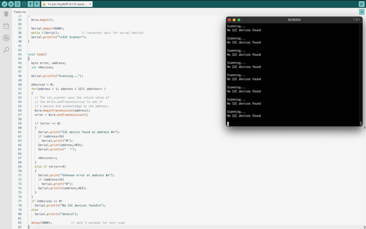
After a while and some trial and errors i got a very general error message from my board.

Tried to see if anything was still coming in.. but then it was time to get a PCR test and get ready for the local and regional meeting.
UPDATE:
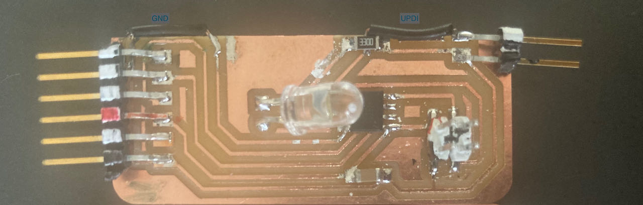
In week 15 i decided since i need a working board for this week to make a new mama board, this time with GND copper pour since when i tried to resolder my 4 pins male into 2 male and 2 female i ended up with the traces coming off and the 2 connectors don’t really fit.
Also by now pretty sure that the old attiny1614 was really fried when i accidentally touched the copper of the other board with both VCC and GND. Which was confirmed to me with the logic analyser only receiving UPDI info till the pin of the 1614.
I had a bit of a setback with a crooked (or different size?) mill, but after replacing it and running mods again i got myself an nice board which i quickly soldered.
Programming mama I2C
First i used a simple blink program to be able to connect mama to the 2 nodes but since i wanted to use the signals in from the KY033 wannabees i needed to figure out how to get that data, so i combined the Arduino code with the I2C code. Took me some time to figure it out but with Nadieh sitting next to me calmly soldering wires i got very far. This will help me so much for my end project.
- Sensor 1 has digital output and is ready made
- Sensor 2 i made with pinLED IR and has analog output
Wire.beginTransmission(0x01); needs to be at the beginning of the conversation
and you always need to end it with Wire.endTransmission();
 #include <Wire.h>

int REDLed = 10; //LED op mamaboard
int Sensor1 = 1; //sensor 1
int Sensor2 = 9; //sensor 2
int sensorValue1 = 0;
int sensorValue2 = 0;

void setup () {
  pinMode(REDLed, OUTPUT);
  Serial.begin(9600);
  Wire.begin();
}
void loop () {

// sensor 1 read outs
    sensorValue1 = digitalRead(Sensor1);

    Wire.beginTransmission(0x01);      // transmit to device 0x01


  if (sensorValue1 == 0)               //if sensor reads 0
  {
      Wire.write(1);                 // sends x
      digitalWrite (REDLed, LOW);
      Serial.print("Sensor1 eq 0: ");
      Serial.println(sensorValue1);
  }
  else                              //if sensor reads anything else then 0
  {
    Wire.write(0);                   // sends x
    digitalWrite (REDLed, HIGH);
    Serial.print("Sensor1 ne 0: ");
    Serial.println(sensorValue1);
  }

Wire.endTransmission();           // stop transmitting

// sensor 2 read outs

    sensorValue2 = analogRead(Sensor2);

    Wire.beginTransmission(0x02);   // transmit to device 0x02

  if (sensorValue2 > 50)            //if sensor reads higher then 50
  {
    Wire.write(0);                 // sends x
    Serial.print("Sensor2: ");
    Serial.println(sensorValue2);
  }
  else                              // if sensor reads lower then 50
  {
    Wire.write(1);                   // sends x
    digitalWrite (REDLed, HIGH);
    Serial.print("Sensor2: ");
    Serial.println(sensorValue2);
  }

  Wire.endTransmission();           // stop transmitting

  //delay(1000);

    Serial.println(" ");             // print empty line

}
Programming the nodes I2C
Also here you have to include the Wire Library with #include <Wire.h>
and give the nodes their own address, in this case Node2 Wire.begin(0x02);
The line Wire.onReceive(receiveEvent); starts the receive event when data is received on this address.
#include <Wire.h>
int LED = 4;
int x = 0;
void setup() {
  // Define the LED pin as Output
  pinMode (LED, OUTPUT);
  // Start the I2C Bus as Slave on address 0x08
//Wire.begin(0x01);
Wire.begin(0x02);

  // Attach a function to trigger when something is received.
   Wire.onReceive(receiveEvent);
  Serial.begin(9600);
}
void receiveEvent(int bytes) {
  while(Wire.available() > 0) {
    x = Wire.read();    // read one character from the I2C
    Serial.println(x);
  };
}
void loop() {
  digitalWrite(LED, LOW);
  //If value received is 0 turn ON daylight LED
  if (x == 0) {
    digitalWrite(LED, HIGH);
  }
  else
       digitalWrite(LED, LOW);

    //delay(500);
  }
i needed a bit more time then 1 week with my ambitious 5 boards but happy i managed and even understand. I find I2C more logic then UART so that’s the road i will follow.
 - NEVER AGAIN use “double” VCC ground pins, only on the FTDI side and the rest should be female, even better separate them from all the signals, a separate female VCC ground to power the board separately.
- i think i can start to round up my search for the right sensor in the next two weeks, leaning towards the tiny KY033 instead of the bulky pin led ones.