Week 13
Output Design
Group assignment Measure the power consumption of an output device
Individual assignment Add an output device to a microcontroller board you’ve designed and program it to do something
Basic
-
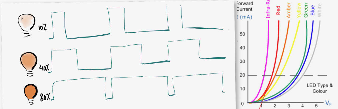
LED does not dim, you could sheet it by using different resistors of a controllable current supply but we use PWM
-
Nominal voltage drop of various common types of LEDs (approximate):
- Red / infrared: 1.9 volts
- Green: 2.1 volts
- Yellow: 2 volts
- Blue / white: 3.6 volt
-
Types of Light Emitting Diode
- Gallium Arsenide (GaAs) – infra-red
- Gallium Arsenide Phosphide (GaAsP) – red to infra-red, orange
- Aluminium Gallium Arsenide Phosphide (AlGaAsP) – high-brightness red, orange-red, orange, and yellow
- Gallium Phosphide (GaP) – red, yellow and green
- Aluminium Gallium Phosphide (AlGaP) – green
- Gallium Nitride (GaN) – green, emerald green
- Gallium Indium Nitride (GaInN) – near ultraviolet, bluish-green and blue
- Silicon Carbide (SiC) – blue as a substrate
- Zinc Selenide (ZnSe) – blue
- Aluminium Gallium Nitride (AlGaN) – ultraviolet
-
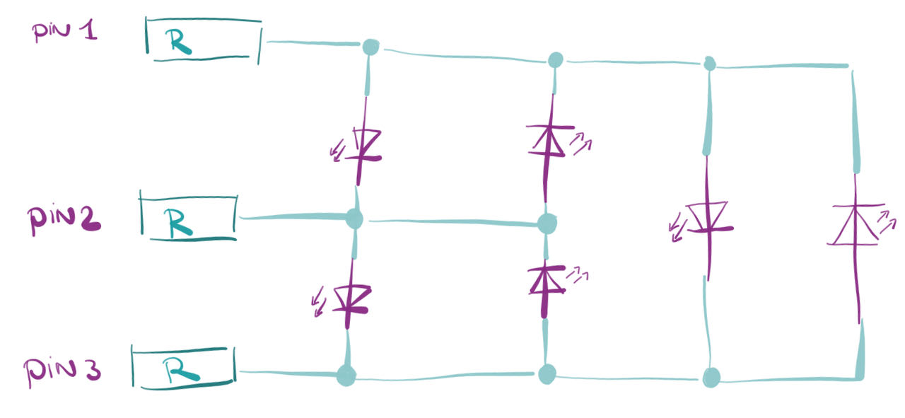
Charlieplexing is a way to control a multiplexed display with relatively few i/o pins from the microcontoller. With 3 pins you are able to control 6 leds and with 4 already 12 - the formula you can use is n + n2 − n.
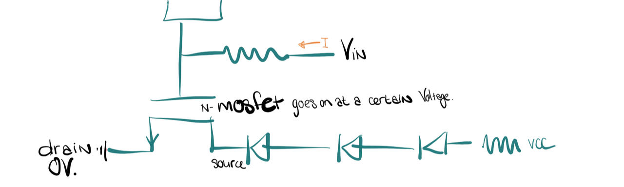
a way to control leds when they are in parallel connection is with aq Mosfet from which you have different versions, this schematic explains the way to connect a N-Mosfet.
-
LCD Liquid Crystal Display
-
TFT Thin Film Liquid Crystal display, uses active matrix addressing.
-
OLED An organic light-emitting diode is a LED in which the emissive electroluminescent layer is a film of organic compound that emits light in reaction to an electric current. Used as digital displays for in smartphones, monitors and so on.
-
FOLED the flexible version of an OLED, worked in to a flexible plastic substrate on which the electroluminescent organic semiconductor is positioned.
-
Audio A loudspeaker is an electro acoustic transducer; a device which converts an electrical audio signal into a corresponding sound, the horn gets pulled in by the current
-
DCMotor is any of a class of rotary electrical motors that converts direct current electrical energy into mechanical energy. The most common types rely on the forces produced by magnetic fields. Nearly all types of DC motors have some internal mechanism, either electromechanical or electronic, to periodically change the direction of current in part of the motor.
-
Brushed DC motor generates torque directly from DC power supplied to the motor by using internal commutation, stationary magnets (permanent or electromagnets), and rotating electromagnets.Advantages of a brushed DC motor include low initial cost, high reliability, and simple control of motor speed. Disadvantages are high maintenance and low life-span for high intensity uses.
-
Servomotor is a specific type of motor that is combined with a rotary encoder or a potentiometer to form a servomechanism. This assembly may in turn form part of another servomechanism. A potentiometer provides a simple analog signal to indicate position, while an encoder provides position and usually speed feedback. Servo control is a method of controlling many types of servos by sending the servo a PWM (pulse-width modulation) signal, a series of repeating pulses of variable width where the width of the pulse determines the position to be achieved by the servo.
-
Piezo uses piezoelectric effect to measure changes in pressure, accelerations and temperature (it’s greek for squeeze)
Group assignment
 - Measure the power consumption of an output device
 - use the controllable power regulator to check power consumption of LED
 - not much to research
 - understand power consumption better
Trying out
Our group used the controllable power regulator to power the different LEDs in order to try to get a better grip on how they use power.
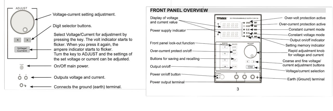
At first we go a bit lost, why does it not using the full Voltage if we feed it 5V and a low current.. because LED use Current not Power as the as i learned on this dutch website
If you connect an LED to a regular voltage source and increase the voltage slowly, almost nothing will happen at first. Only when the voltage approaches the nominal voltage drop, current starts to flow and the LED lights up. However, if the voltage is increased even slightly after that (a few tenths of a volt), the current will increase very quickly, until the LED breaks.
In principle, such an exponential relationship between voltage and current applies to all diodes; however, the exact values of the nominal voltage drop and current are highly dependent on the type of diode. Most common LEDs are driven with a current of up to 20 mA (milli-amps), or 0.02 amps. The value of the nominal voltage drop depends on the color of the LED; with red LEDs this is usually about 1.9 volts, with yellow and green LEDs 2.0 and 2.1 volts respectively, and with blue and white LEDs 3.6 volts.
Found a very handy ledcalculator to calculate the Current and/or Resistor for you.
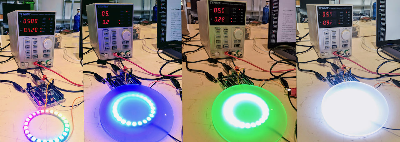
Neopixel ring (24 leds)
We started with a rainbow ring since that’s Nadieh her go to, but quickly realized we should start simple with 1 color at a time.
With 5V - 0.001A it would use 0.16V - 0.001A and only half the ring would go on in Red.
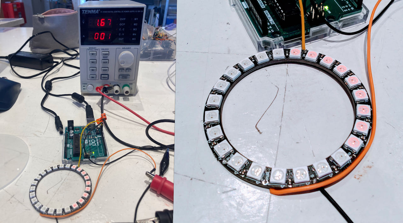
They higher we would turn the current the brighter the LED would be which fits the theory.
With 5V - 1.4A all the separated colors used:
- Blue 0.288A
- Rood 0.288A
- Green 0.286A
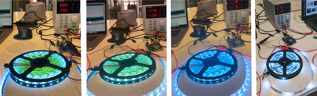
Neopixel strip (300 leds)
Started with 5V - 1.4A (used 3.88V -1.4A) on one side and realized when the strip got power from one side it would “loose” it in the length of the strip, the resistance got to much. Connecting the other side of the strip helped a lot already then we boosted up to 5V - 3.1A.
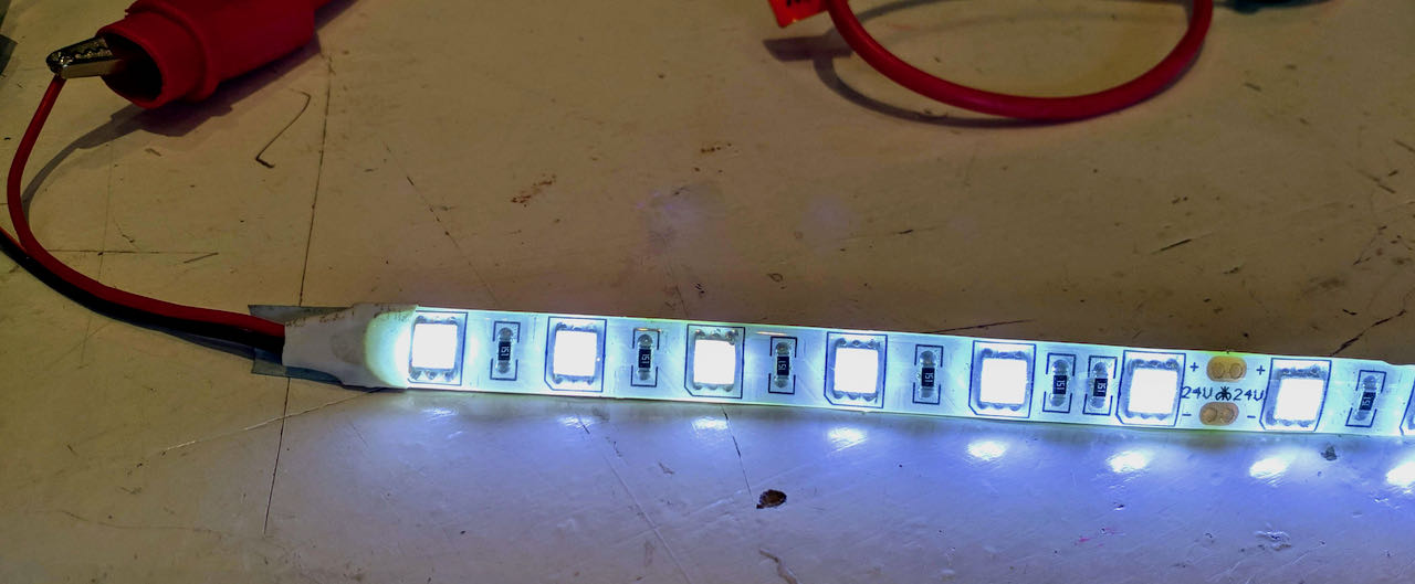
a single “normal 24V” ledstrip with R 150 Ohm between them.
Individual assignment
- Add an output device to a micro controller board you’ve designed and program it to do something
- use input and output in a board.
- figure out the different outputs from Neil’s lecture
- make a working board
As always it’s quick decision time, what to make and where to start, since my input board was not such a great success i challenged myself to try again.
Components
IR phototransistor and IR LED
I want to try to use a IR phototransistor and and IR LED to try to figure out if i can use this for my end project, since it will be dark in the box i would be great if with this system i can measure if there is something or nothing in front of the sensor. At the Waag we have these IR PHOTOTRANSISTORS and these IR LEDS. Found their datasheets online and used the information from it to calculate the resistor i would have to use.
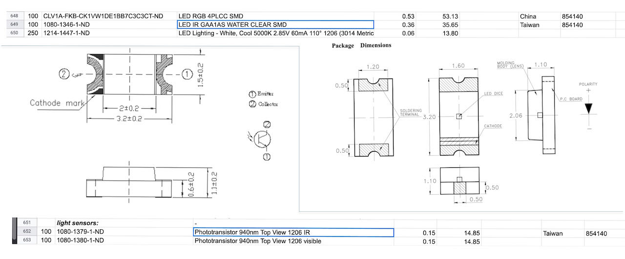
The formula for calculating a resistor for a LED is (V-Vf)/If
The problem with infrared LEDs is that the emitted infrared light is invisible to the naked eye. The nice thing is that most electronic cameras are sensitive to this infrared light. So if you have a digital photo or video camera, or even a simple webcam, you can check whether an infrared LED is emitting light.
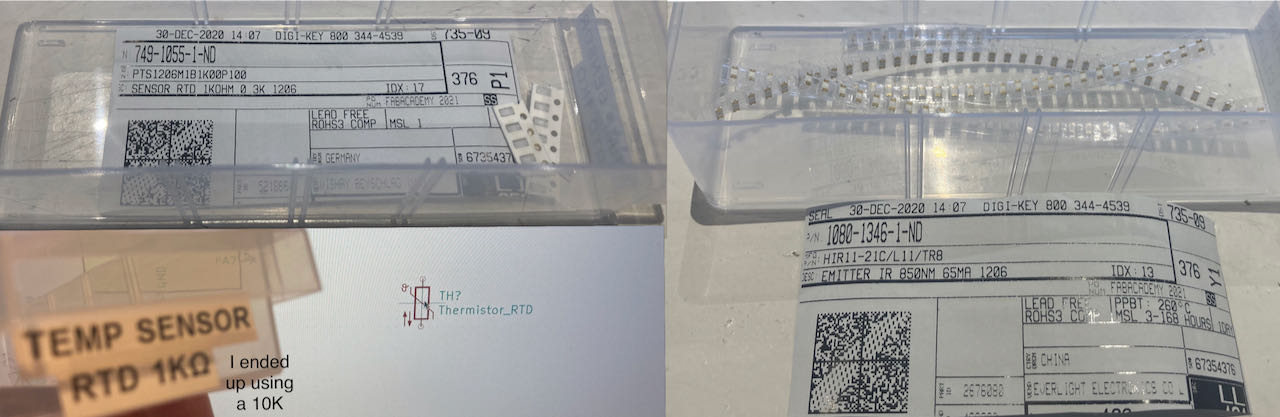
Thermistor
For the thermistor i had to get through a bit of different version on line to find the right way of doing it but the site from Noor really helped me with figuring it out.
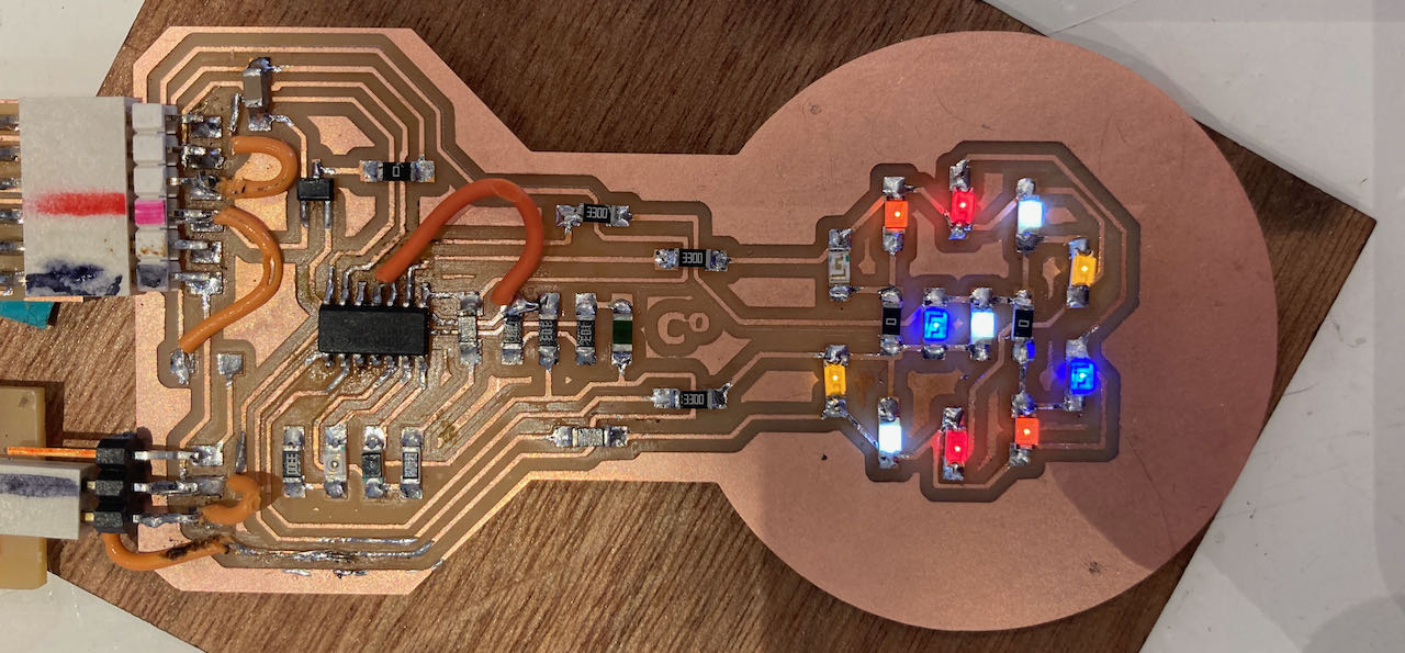
Charlieplexing
Charlieplexing is a way to control a multiplexed display with relatively few i/o pins from the microcontoller. With 3 pins you are able to control 6 leds and with 4 already 12 - the formula you can use is n + n2 − n.
Found this great link for charlieplexing which is with an Arduino but it helped me to understand, als this youtubelink makes it visually understandable.
Later on i found a hack a day site which also used an AT tiny so that gave me a bit of a clearer view on how to make it work with the ATtiny.
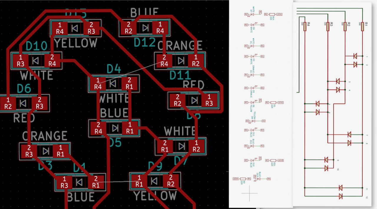
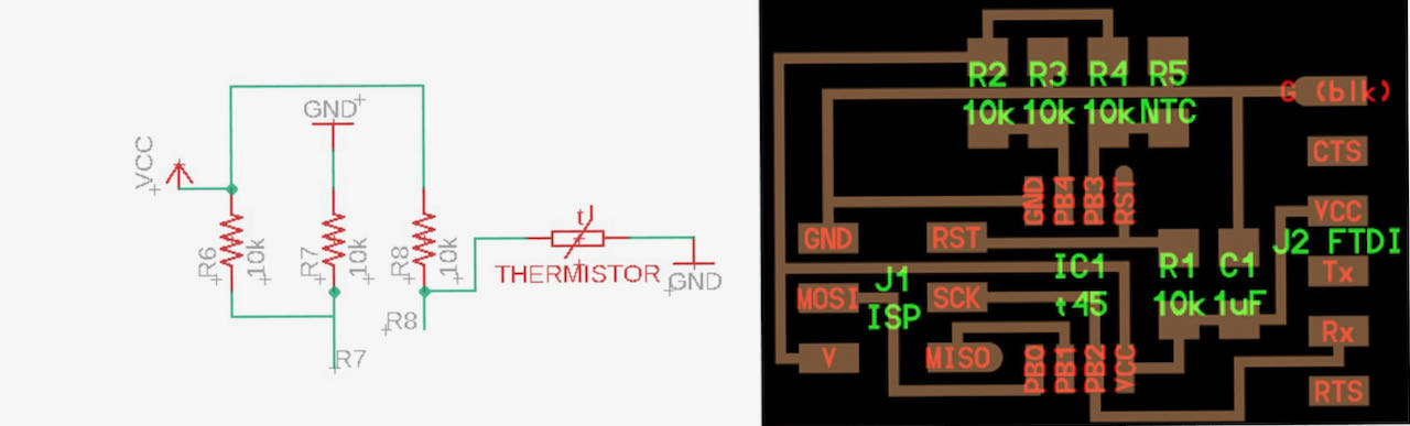
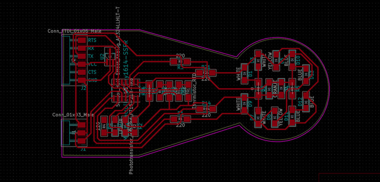
In Kicad i put the flags of the different resistors instead of drawing it as a schematic, not sure if that was smart, the schematic does give a clearer overview when you want to look back.
Now that i am using different LEDS i will have to look up their orientations, one of the LEDS have this version:

The white ones have the T on it which i used before, for reference i made this little drawing:
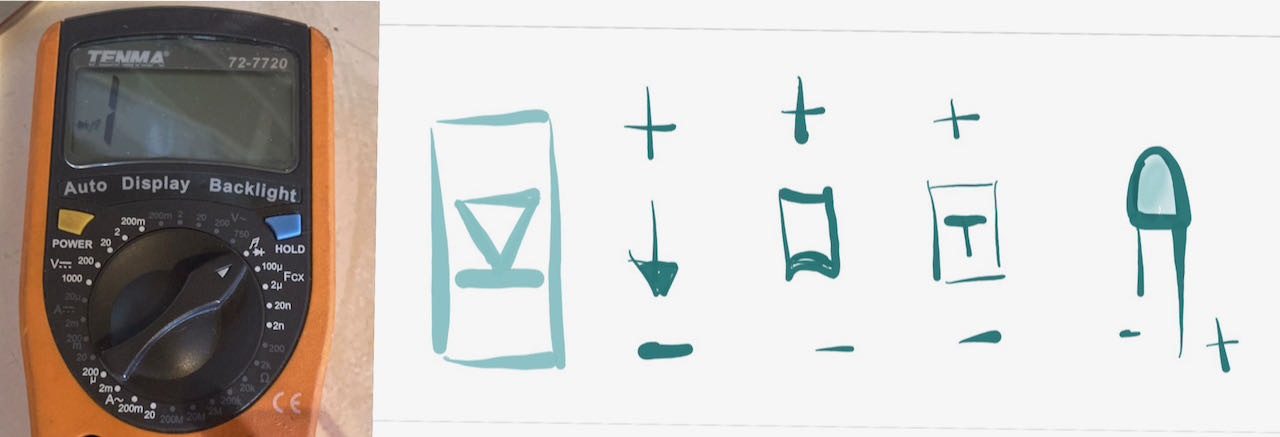
with the multimeter you can quickly check if they are working and the right color. If only i did this the first time i put it was soldering, 4 wrong colors …
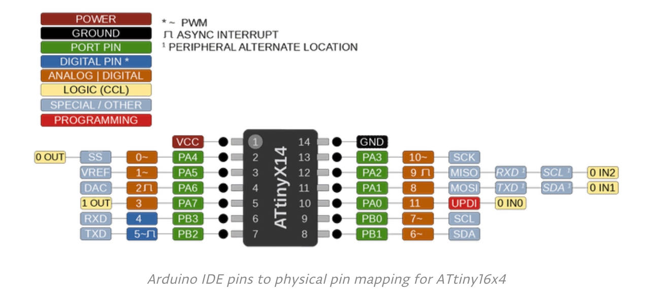
ATtiny 1614
The Attiny 1614 has many names, it’s listed at Atiny14 and AtinyX4. Below is the pin out for it, for the LEDS i wanted to use pwm pins in case i needed to dim which is indicated with a ~ The numbers on the controller are not the number you use in Arduino ide, there you use from pin 2 till pin 13 and they are numbered from 0 till 10.
List of components to solder
| Amount | component | direction | .. |
|---|---|---|---|
| 3x | blue led | yes | |
| 3x | white led | yes | |
| 2x | yellow led | yes | |
| 2x | orange led | yes | |
| 2x | red led | yes | |
| 4x | 330 Ohm resistors | no | for the leds |
| 1x | IR LED | yes | GAA1AS |
| 1x | 330 Ohm resistor | no | for the thermistor |
| 1x | IR Phototransistor | yes | 940 Ohm top |
| 1x | 10K resistor | no | for the transistor |
| 1x | hall sensor analog | yes | |
| 1x | 10K thermistor | no | RTD 10K |
| 3x | 10K resistors | no | for the thermistor |
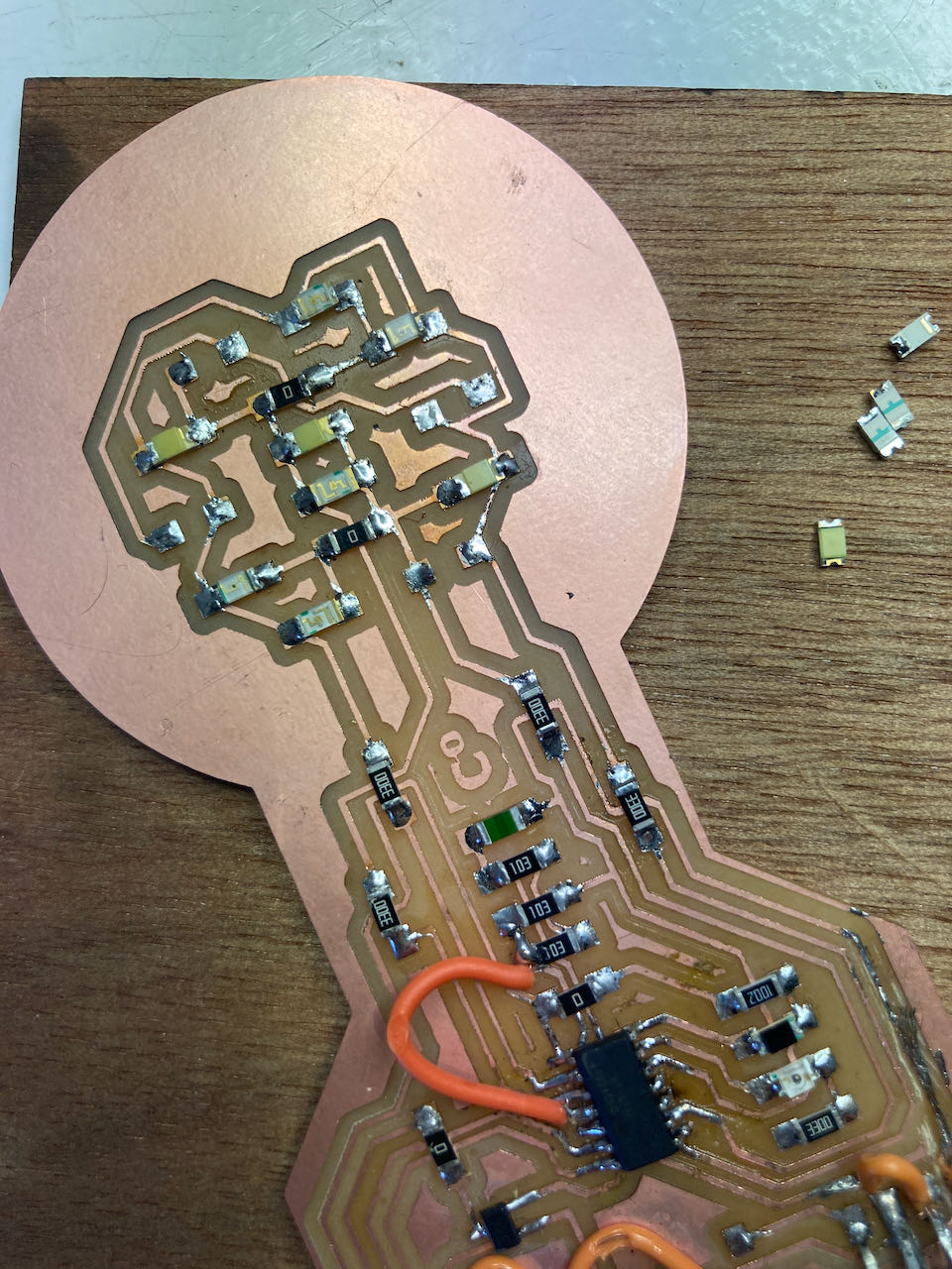
The PCB i made in Kicad was a bit to messy, so many R0, couldn’t understand why except that my focus must be off.
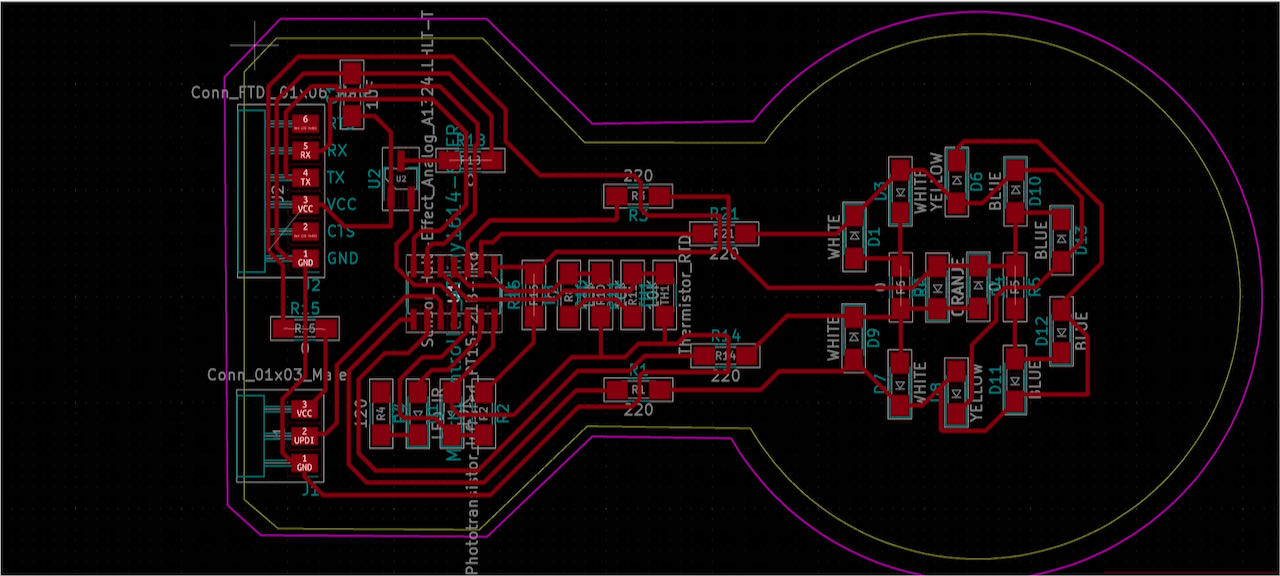
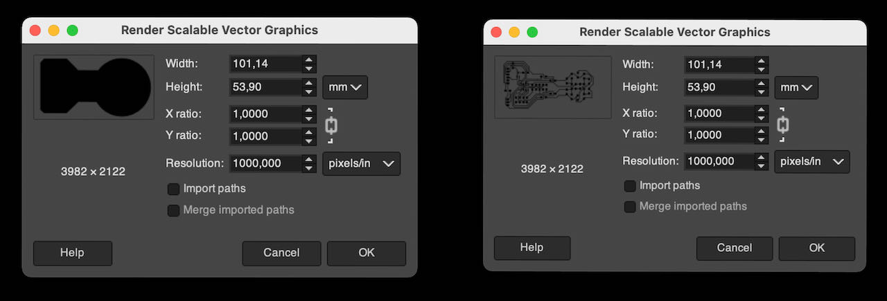
When importing my file into Gimp i could see the size of the PCD i created, if only i made it 1cm smaller it would have fit on to the copperplate that was still there from Nadieh her milling, but at least i got to practice at putting a plate on the sacrificial layer.
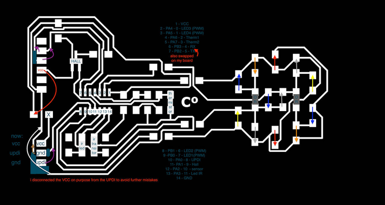
When i finished soldering i realized how many stupid mistakes i made (first one was putting female instead of male connectors..) i decided to get my act together and make an overview of things to fix:
- switch RX and TX (i thought)
- connect the VCC at the pin for whatever reason i overlooked the little white stripe still there in Kicad
- check all the LED directions, only 1 wrong to my surprise.
- and as i seem to do every week fix my UPDI pins. (next time use a fab pre-labeled one)
When i made all the bypasses which i am getting better and better at i connected it to my computer and got this:
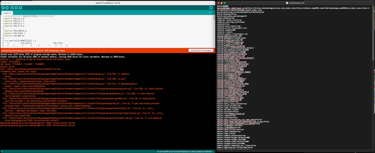
First tried the fix i used before by adding a line of text in the preference file but it was already there, so thats not it. For future reference i will explain it below here:
- go to preferences in Arduino IDE
- click on the link that goes to preference.txt this opens the folder of that file.
- close the arduino ide and then open the file (in this order)
- add a line to create a variable for the build.path (this will hold all the files you will create with the arduino ide)
- Made a folder named build within the Arduino folder and referred to it in the preferences.txt file.
build.path=/users/loes/Documents/Arduino/buildas you can see in the picture above.- then open the Arduino ide again.
- this procedure you use for
pyupdiprogramming which is not really necessary since we have the Arduino IDE, wrongly remember but anyways good to check :)
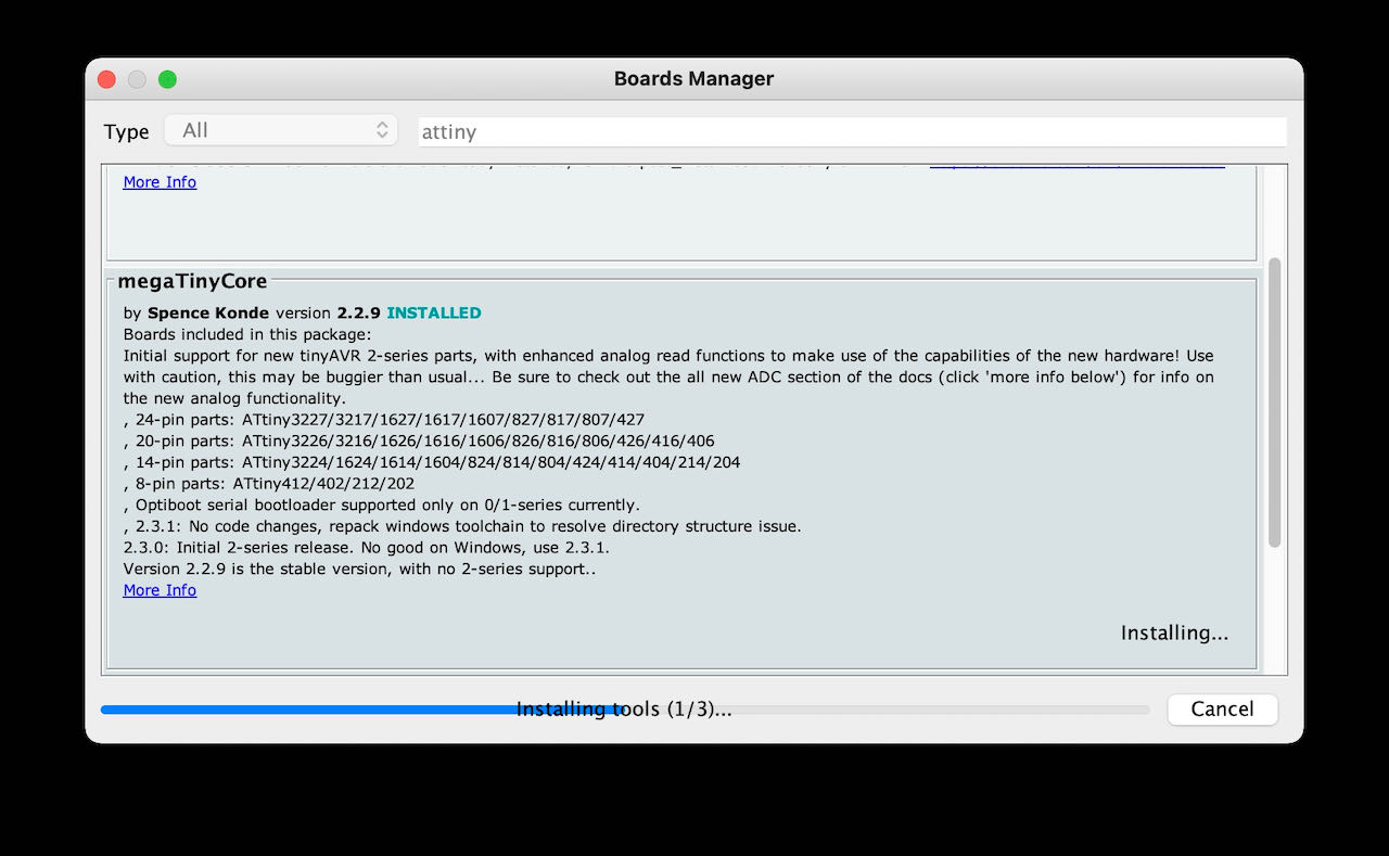
The only other thing i could think off was to update the Mega core library.
Strangely enough the blue led is on.. which is my mistake.. its the wrong way around but still that indicates something.. but what? This LED was still the wrong way around..
So there must be something else wrong with my board..
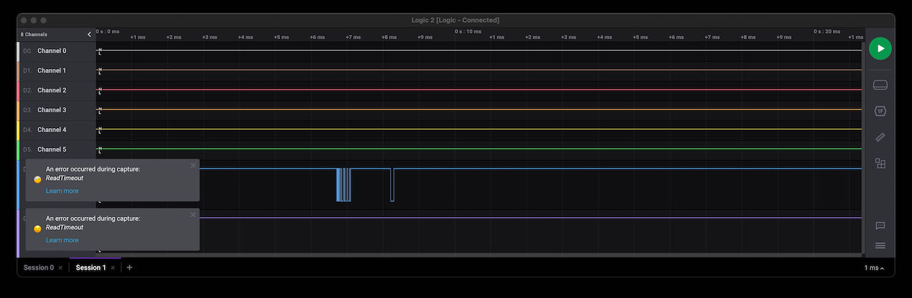
I tried to use the logic analyser to check the signal across the UPDI path but was to difficult to keep the connections steady with these hooks i got from Lucia, thanks for them but way to big for the tiny ATtiny legs.
After a while i realized it’s never gonna work from home without the proper equipment (little tip for the next electronics kit, add this little grabbers that you can use with your logic analyser) so decided to make a working version at least in Kicad, which was so much easier to connect with the right use of pins :) Although i probably will not have the LAB time to mill its since there are still 6 people that have to mill as far as i know and i really want to start programming this week…
When I arrived at the Waag on Monday morning the first thing I did was to check with the help of Nadieh her sweet little grabbers to connect to the logic analyzer pins.
We quickly realized that the UPDI trace seemed fine and it would arrive at the ATtiny perfectly but when it went under the chip to reach its pin nr 10 it seems to loose its stability. When I took the microchip off I was welcomed with these messy traces.
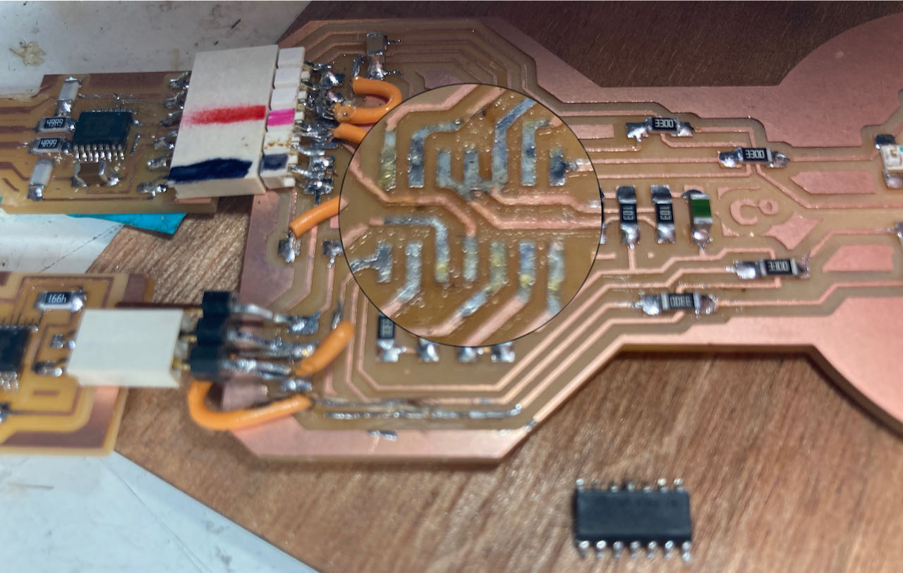
The traces were so close that they connected. did check in the 3D view in mods unfortunately I relied to much on the software, since I was very careful putting the right board setup but I guess I must have moved them or moved the ATtiny, no idea but I was time to fix it. Plus i also found out another strange mistakes.. the ATtiny was the wrong way around, this was really a week with mistake on mistake. The good thing is that i learn so much. For instance that the dot from the ATtiny should always be at the VCC side.
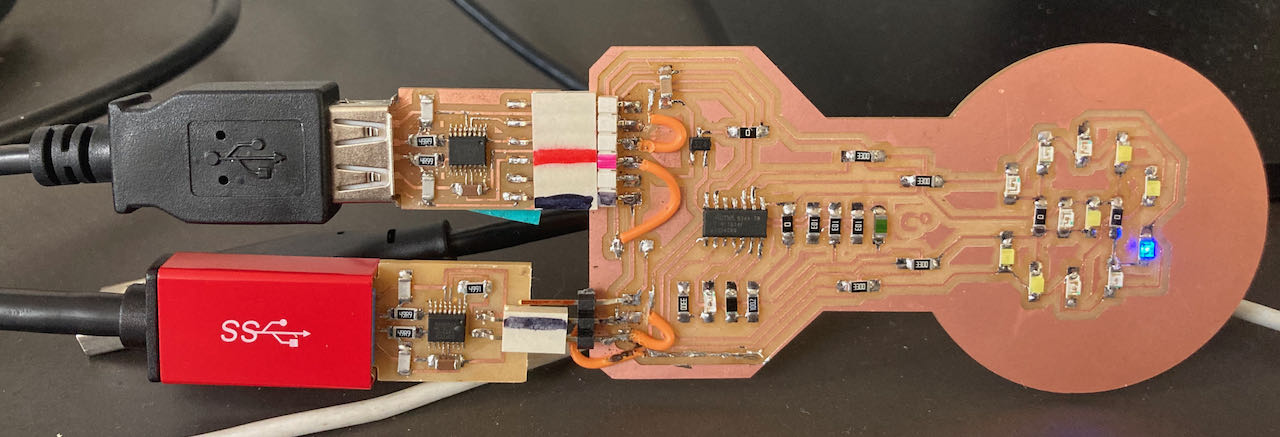
With the board now responding to the Arduino IDE I could finally check the Charlie plexing, which was made easier for me with the help off Nadieh and her code.
Serial monitor
Then arrived the moment I tried to read the serial monitors (separate from the Arduino IDE) with this helpful terminal commando
screen /dev/tty.usbserial-D30A3T7W 9600 the last number is the serial baudrate and the one before the “name” of my FTDI.
When you want it to stop use ctrl a and then ctrl / and then finally Y in the screen from terminal.
The screen stayed empty.. even with a simple
serial.print ("hoi")
With the logic analyzer I soon found out with putting the sniffer on the rx pin (which is connected to tx of the ATtiny) that there was lots of signal coming in …
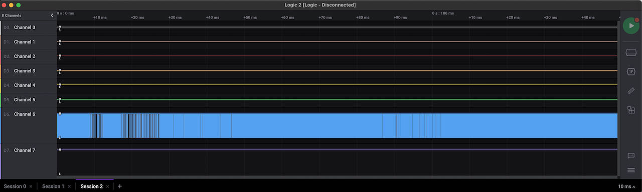 wrong header pin… my god… I swapped something that was actually right the first go! No way I am changing it back again.. using a cable to swap the pins from now on.. can’t wait for the moment I have a board that works in one go.
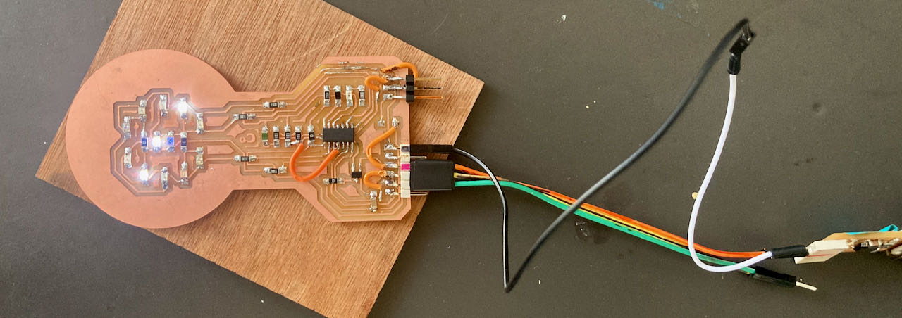
It looks so messy but proud of my debugging this week, learned a lot.
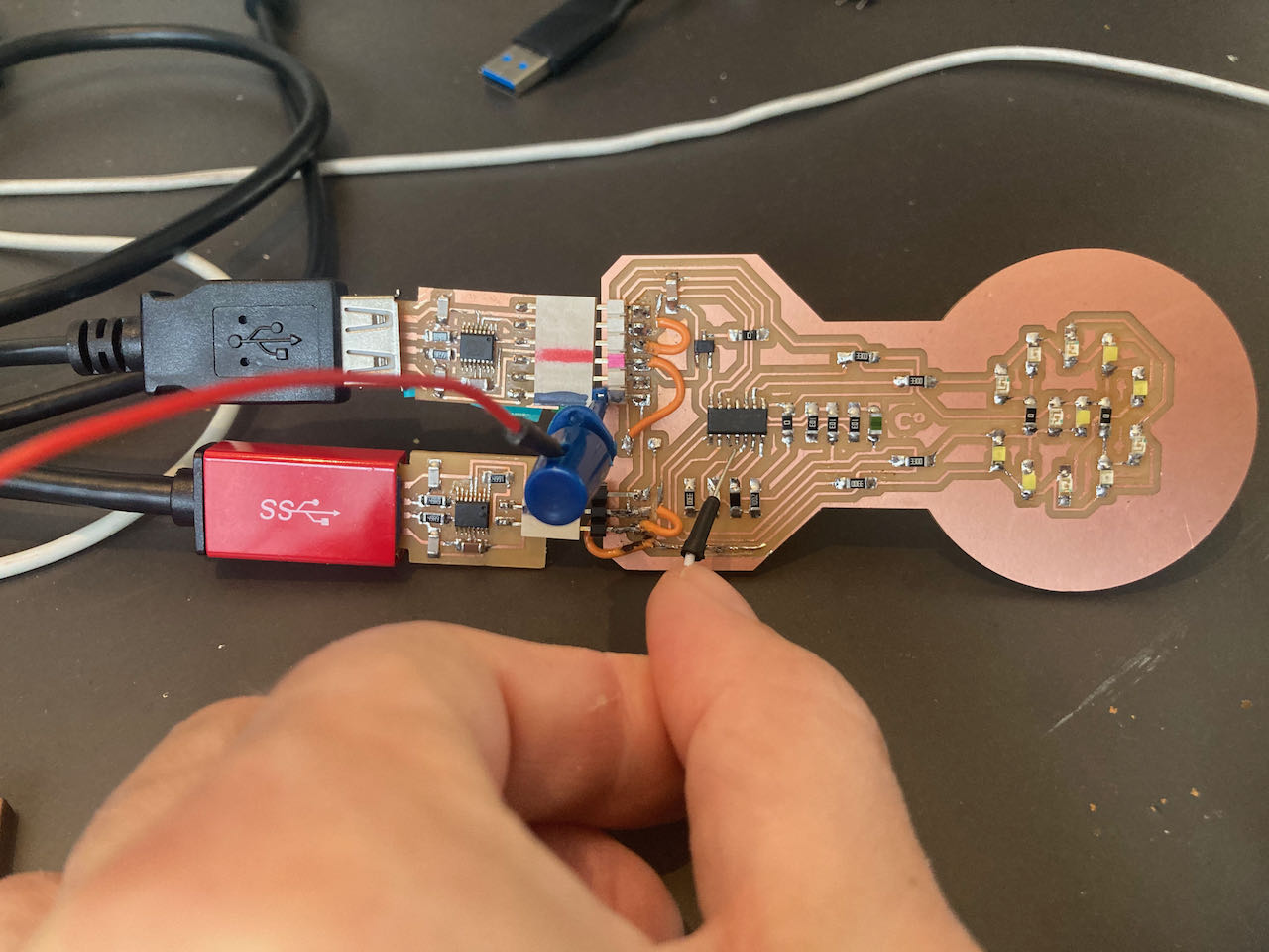
One last “bypass” was needed, when i tried to take of my UPDI the board would switch off, like it would have power, first thing i thought was ground must be lacking so i made a little bypass so connect the ground to the FTDI and it worked.. now finally some coding.
Programming the board
Charlieplexing
define the pins for the Charlieplexing
//Charlieplexing
#define PIN_CP_1 0
#define PIN_CP_2 1
#define PIN_CP_3 7
#define PIN_CP_4 6

// for the charlieplexing matrix calculation below
#define PIN_CONFIG 0
#define PIN_STATE 1
// amount of leds
#define LED_NUM 12

// led matrix
int matrix[LED_NUM][2][4] = {
  //           PIN_CONFIG                    PIN_STATE
  //    1       2       3      4         1     2    3    4
  { { OUTPUT, OUTPUT, INPUT, INPUT }, { HIGH, LOW, LOW, LOW } }, //0 - yellow
  { { OUTPUT, OUTPUT, INPUT, INPUT }, { LOW, HIGH, LOW, LOW } }, //1 - white
  { { INPUT, OUTPUT, OUTPUT, INPUT }, { LOW, HIGH, LOW, LOW } }, //2 - blue
  { { INPUT, OUTPUT, OUTPUT, INPUT }, { LOW, LOW, HIGH, LOW } }, //3 - white
  { { INPUT, INPUT, OUTPUT, OUTPUT }, { LOW, LOW, HIGH, LOW } }, //4 - white
  { { INPUT, INPUT, OUTPUT, OUTPUT }, { LOW, LOW, LOW, HIGH } }, //5 - yellow
  { { OUTPUT, INPUT, OUTPUT, INPUT }, { HIGH, LOW, LOW, LOW } }, //6 - blue
  { { OUTPUT, INPUT, OUTPUT, INPUT }, { LOW, LOW, HIGH, LOW } }, //7 - orange
  { { INPUT, OUTPUT, INPUT, OUTPUT }, { LOW, HIGH, LOW, LOW } }, //8 - orange
  { { INPUT, OUTPUT, INPUT, OUTPUT }, { LOW, LOW, LOW, HIGH } }, //9 - blue
  { { OUTPUT, INPUT, INPUT, OUTPUT }, { HIGH, LOW, LOW, LOW } }, //10 - RED
  { { OUTPUT, INPUT, INPUT, OUTPUT }, { LOW, LOW, LOW, HIGH } }  //11 - RED
};

void lightOn( int led ) {
  pinMode( PIN_CP_1, matrix[led][PIN_CONFIG][0] );
  pinMode( PIN_CP_2, matrix[led][PIN_CONFIG][1] );
  pinMode( PIN_CP_3, matrix[led][PIN_CONFIG][2] );
  pinMode( PIN_CP_4, matrix[led][PIN_CONFIG][3] );
  digitalWrite( PIN_CP_1, matrix[led][PIN_STATE][0] );
  digitalWrite( PIN_CP_2, matrix[led][PIN_STATE][1] );
  digitalWrite( PIN_CP_3, matrix[led][PIN_STATE][2] );
  digitalWrite( PIN_CP_4, matrix[led][PIN_STATE][3] );
}//void lightOn
made voids for the separate colors, by turning them on and off very fast they seems on.
void  whitelight() {
  //Seemingly all on
 lightOn(1);
 delay(1);
 lightOn(3);
 delay(1);
 lightOn(4);
 delay(1);
}//void whitelight
Final programming
Since i had a bit of a hard time the input week i want to use this week to learn a bit more about input programming also so i used a thermistor as input and made the leds react to the temperatuur (which in practice means that you will have to put you finger on it to make it work).
This i what i ended up with:
 #define Thermistor_pin 3

int base_thermistor_value = 0;

void setup() {
  Serial.begin(9600);
   pinMode (Thermistor_pin,INPUT);
Use void within voids to make it work:
  int Thermistor_value = analogRead(Thermistor_pin) ;

      Serial.print("Thermistor Analog ");
      Serial.println(Thermistor_value);

      delay(0); // took the delay out since the led void already lasts 3 sec or so.. how do i calculate this?

  if(Thermistor_value > (base_thermistor_value + 1) || Thermistor_value < (base_thermistor_value - 1)) {

 //seemingly 2 yellow leds on
  for(int l = 0; l < 150; l++) {
   yellowlight();
 }
 //seemingly 2 orange leds on
  for(int l = 0; l < 150; l++) {
   orangelight();
 }
 //seemingly 2 red leds on
  for(int l = 0; l < 150; l++) {
   redlight();
 }
   } //if

  else
   {
    //seemingly 3 blue leds on
  for(int l = 0; l < 300; l++) {
   bluelight();
 }
 //seemingly 3 white leds on
 for(int l = 0; l < 300; l++) {
   whitelight();
 }
}//else
- Lots of traces issues, stupid mistakes but got in to programming finally
 - take more time and double check the traces.
- think about the board i wanna make to prepare for my final project