Week 06
Electronics Design
Group assignment Use the test equipment in your lab to observe the operation of a micro controller circuit board (in minimum, check operating voltage on the board with multimeter or voltmeter and use oscilloscope to check noise of operating voltage and interpret a data signal) Individual assignment Redraw one of the echo hello-world boards or something equivalent, add (at least) a button and LED (with current-limiting resistor) or equivalent input and output, check the design rules, make it, test it.
Group assignment
 - Use the test equipment in your lab to observe the operation of a micro controller circuit board (in minimum, check operating voltage on the board with multimeter or voltmeter and use oscilloscope to check noise of operating voltage and interpret a data signal)
 - Find out what tools there are to use and which to choose for what purpose
 - Lots of google and reading students documentation, Tessel her page got recommended by Henk.
 - Make a comprihensive list of components so that i can understand the logic
Testing and observe
Before and during the group assigment Henk was giving us a quick tour through Kicad (the software to make your own PCB), it turned out to be a challenge from the beginning with Kicad and Mac..
Once we got it started the first thing we wanted to do was to install the symbols that were recommended by Neil, after downloading it from Gitlab (i downloaded the zip) we had to find a way to get it on the proper place on our system. We ended up just copying it into the Kicad application folder. The default in Kicad was to create a library when importing one but after some try out we realized you have to create an empty library and then import the downloaded on in there. While starting with making the board in the schematic layout editor (see below in the individual assignment) we quickly realized that the library didn’t have the basics like VCC and GND in there so we went back to the beginning and found the library that we had to add to be able to really start creating the board. Henk started a board with an ATTiny412 and some other components, which ones is not so important because we basicly were learing on how the workflow works, how to make it work properly is for the individual assignment.
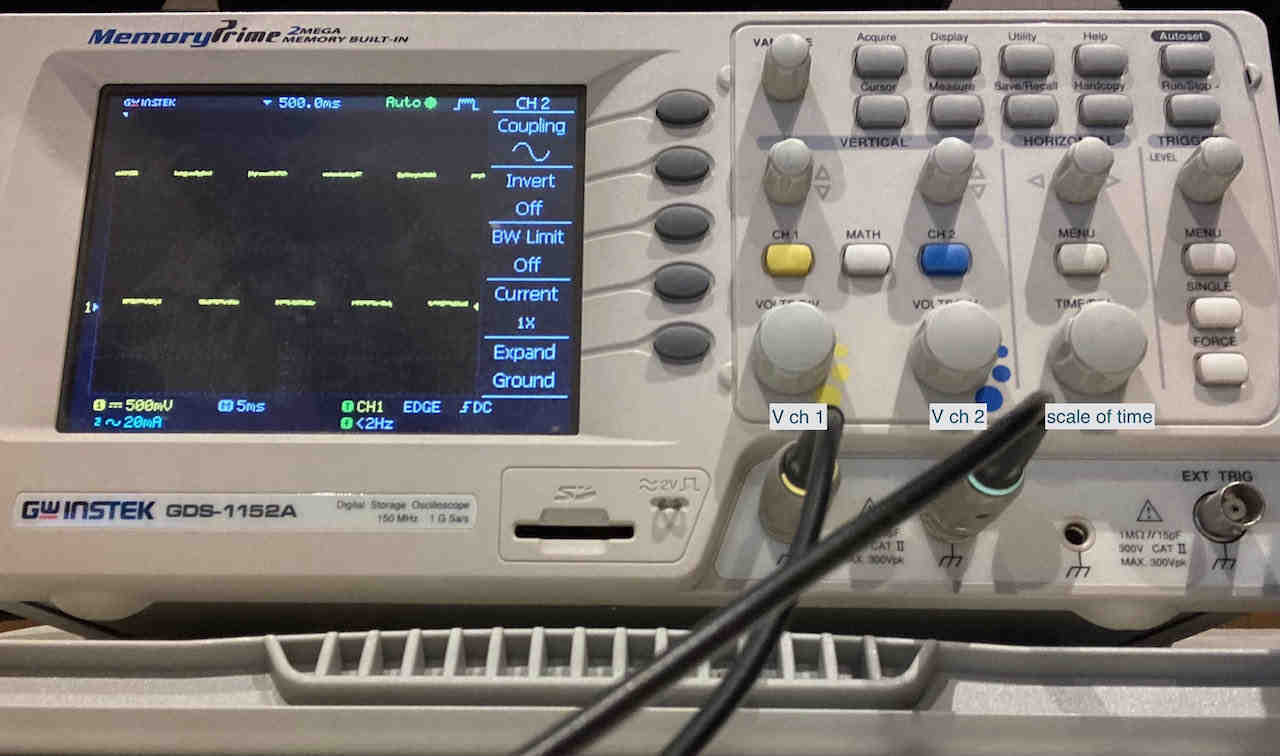
Oscilloscope
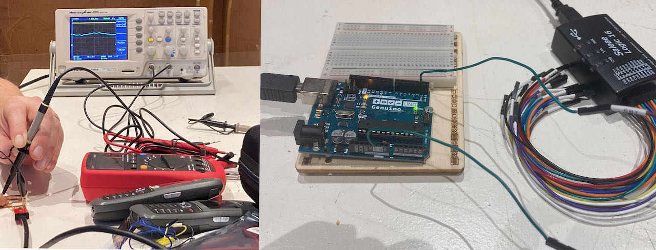
In the afternoon Henk created a set up with the oscilloscope which i found fascinating but don’t really fully understand, i do understand that its measuring signal across time and you can even record it but how and when to use it will become more clear in the coming weeks.
Wikipedia helped me to know the theory: oscilloscope graphically displays varying signal voltages, usually as a calibrated two-dimensional plot of one or more signals as a function of time.
Logic Analyzer
A Logic Analyser captures and displays multiple signals from a digital system or digital circuit. A logic analyzer may convert the captured data into timing diagrams, protocol decodes, state machine traces, assembly language, or may correlate assembly with source-level software. Logic analyzers have advanced triggering capabilities, and are useful when a user needs to see the timing relationships between many signals in a digital systemThe nice bonus about using a logic analyser is that the signal is digitalized so you can analyse it on the computer with different software, we tried Logic2 and Pulseview at the lab.
Multimeter
Multimeter is a tool i am a bit more used to although not in this tiny scale. They can measure different things, depending on the model it can vary but these are the basics:
First always try to connect the ground (black) first to the component or trace, then the red positive wire.
Continuity this we use most for testing circuits, it allows us to test for conductivity of material and trace where electrical connections have been made or not made. Set the meter to continuity and check if it works by touching the pins together, it should biep.
Resistance similar to continuity but now you are checking the actual resistance between 2 points in an electrical circuit- Ω
Measuring Current Current it the rate of moving charges in a circuit. In order to capture the rate of this you need to break the circuit and put the meter in line of where you want to measure. Move the knob to the current range you expect to find. Be careful not to exceed the current limits this may blow the fuse on the multimeter.
Measuring Voltage Voltage is a measurment of electrical potential between 2 points. Similar to measuring resistance you need to find the range of which you are measuring and determine if its DC (2 straight lines) or AC (wave).
Here you can find a great PDF on how to use a multimeter
In the lab we also have fun digital tweezers (DT71 Mini), they don’t need much adjusting, if all goes well they figure out for you what you are trying to measure and tell you. Needs a bit of practice..
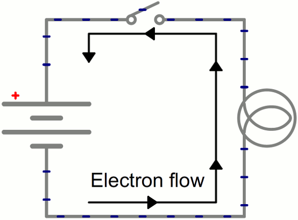
Electronic circuit
An electric circuit consist out of:
| Unit | symbol | measured in | .. |
|---|---|---|---|
| Power | P | Watt | electric energy that goes through the circuit |
| Voltage | V | Volt | difference in electric potential between 2 points |
| Current | I | Amperes | the rate of moving charges in a circuit |
I’ve enjoyed reading this tutorial to get back some of the basics. and for understanding better the electronic design i also went through the presentation from Ferdinand Meier.
Power
-
AC is alternating current, in the Netherlands we have 230V coming from the socket in the wall
-
DC is direct current which is from battery and so on.
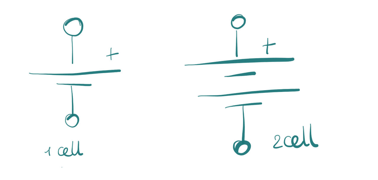
 Battery have a plus (VCC, V, V+ or +V) and a minus side (GND), in between them there is a voltage difference. Depending on the battery this can be different voltage, from a 9V black or AAA (1.5V) battery.
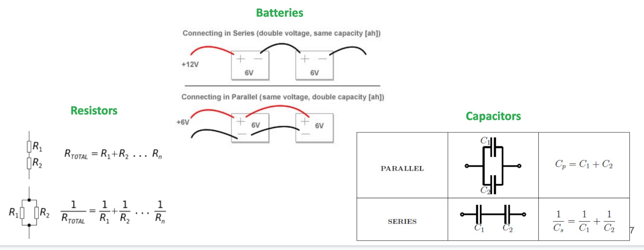
Parallel and Series
Components can be connected in so many different ways, the 2 most simple ones are parallel and serie. In serie means that all the components are on the same path so they same current flows through all the components in batteries it would mean that if you have 2x 6V it would add up to 12V. When parallel the Voltage stays the same but the capacity goes up.
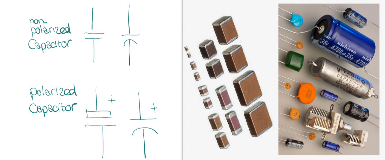
Capacitor
A capacitor can charge and release energy, like a mini battery. but the system is more like a bucket of water on a edge, it stores all the it gets till its full and then releases all at once. It’s measured in F (Farad). They are basicly there to keep the voltage constant. SMD capacitors are tiny rectangles with a color that signifies its capacitance value, while for THT capacitors you can have several difference kinds of shapes, such as cylinders and flattened spheres, with the values written on top. If they get a higher voltage then there maximum they are likely to explode
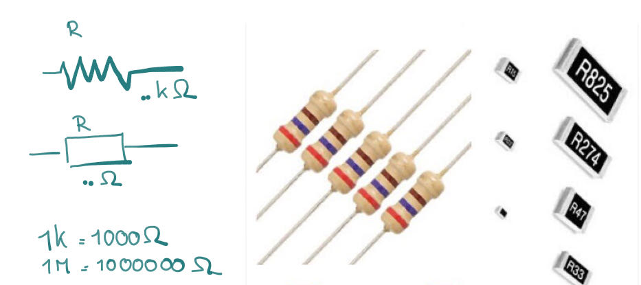
Resistor
Are capable of controlling the current flowing through a circuit, they convert the energy they they get into heat, which means they can also overheat, so check the maximum rating, play it save and use double the value.
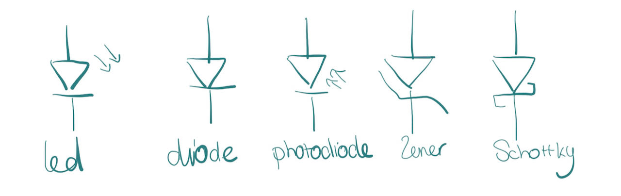
DIODE
The most famous diode of them all is the LED
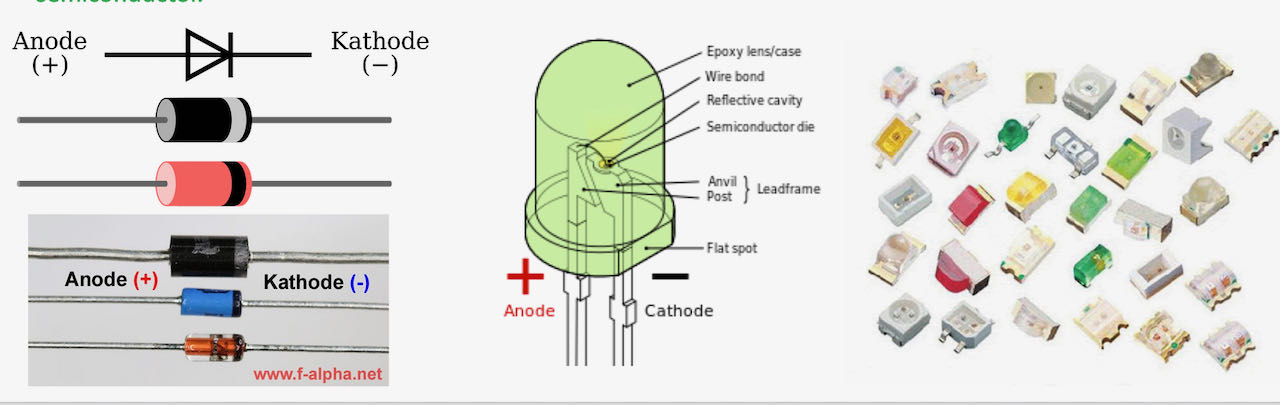
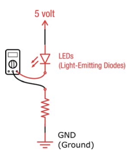
Only letting current flow in one direction, diodes can be used to protect a circuit from accidentally connecting a power source in the wrong direction, and to help go from AC to DC current. But LEDs can of course be used simply to have a (blinking) light. A LED creates no resistance in the circuit. A LED will create a short circuit if you connect it directly to power thus destroy the LED. There needs to be a resistor before it to control the current to the amount the specific LED can handle.
However, there is something called a voltage drop, forward bias, or forward voltage (Vf). Diodes need to have a certain threshold of voltage running through it, before any current will flow across it. There is also a forward current (If) which is the maximum current it can handle.
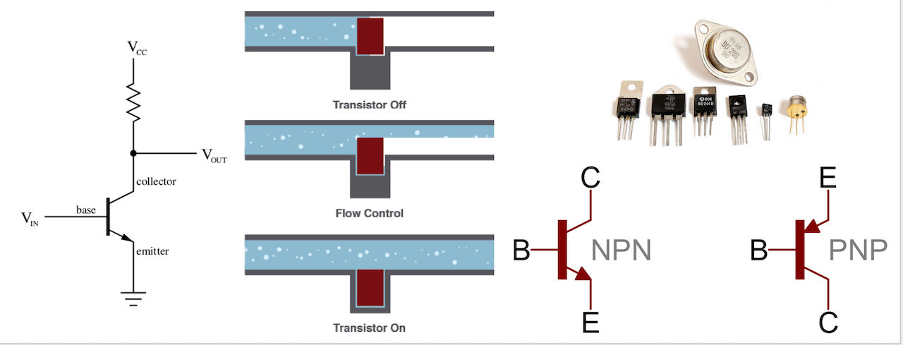
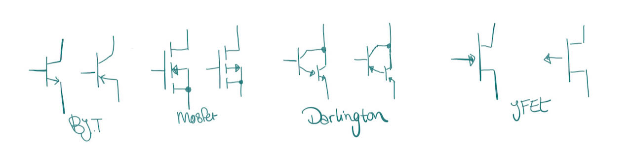
Transistor
Transistors giving you the control over the amount of current that flows. How it works i will have to dive into a bit deeper, will start by watching this video
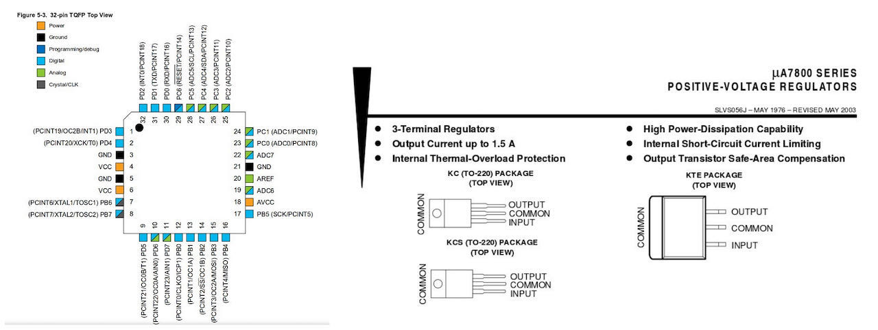
Datasheet
A datasheet is a document that summarizes the performance and other technical characteristics of a product, machine, component (e.g., an electronic component), material, a subsystem (e.g., a power supply) or software in sufficient detail to be used by a design engineer to integrate the component into a system. Typically, a datasheet is created by the component/subsystem/software manufacturer and begins with an introductory page describing the rest of the document, followed by listings of specific characteristics, with further information on the connectivity of the devices.
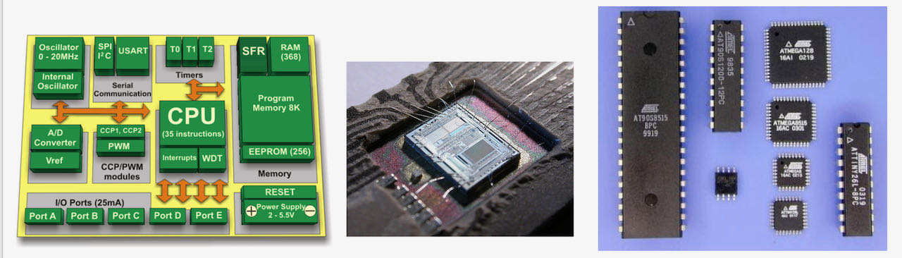
Micro contoller
A micro controller (or MCU) is a small computer on a single integrated circuit containing a processor core, memory, and programmable input/output peripherals. Micro controllers are designed for embedded applications, in contrast to the microprocessors used in personal computers or other general purpose applications consisting of various discrete chips. Micro controllers are used in automatically controlled products and devices, such as automobile engine control systems, implantable medical devices, remote controls, office machines, appliances, power tools, toys and other embedded systems.
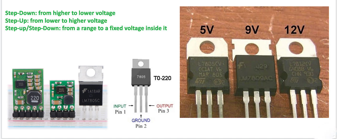
Step down
not sure if this is the same one as an resistor, will have to do a bit of research, found it on the tutorial from Ferdinand.
individual assignment
- Redraw one of the echo hello-world boards or something equivalent, add (at least) a button and LED (with current-limiting resistor) or equivalent input and output, check the design rules, make it, test it.
- Keep it functional, worry less about appearance
- read though fellow student their docu to figure out the right workflow.
- make it work in 1 try, instead of the 20x with the Jtag 2 weeks ago
Designing the board in Kicad
Henk has send us the components which to use so we didn’t have to design from scratch, which helped because just to put all the components together and trace them the right way was already a big enough challenge.
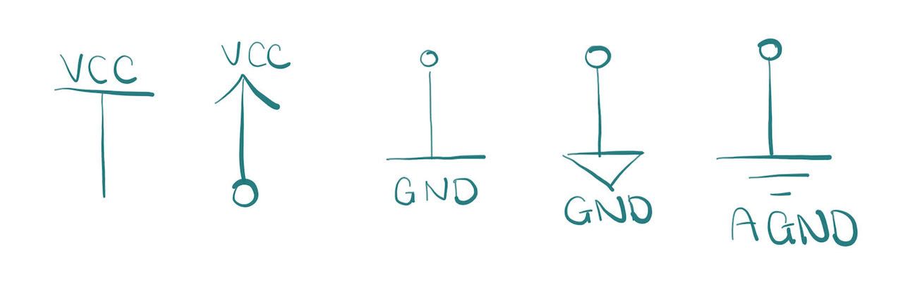
In Kicad there are fun but not very logic symbols so to make my life easier i’ve explained them down here:
The top main-toolbar (which are basically different apps)
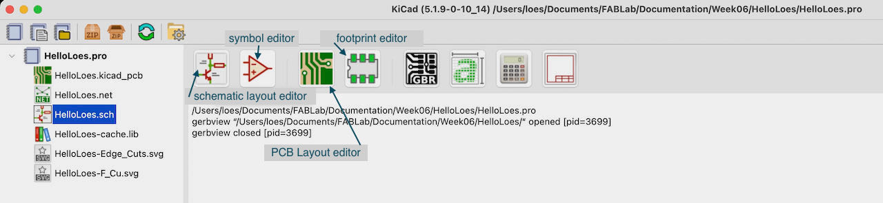
The right toolbar:

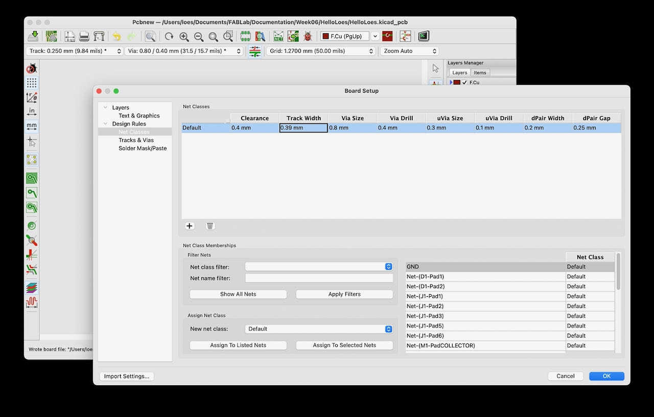
before i did anything i changed to board setup to the ones that Henk used to work with our Motorola.
The very first window you start your pcb in:
Symbols/components
First inserting all the symbols:
- click on symbol icon
- click in window
- window appears where you can search for your component ![Symbol][3353]
- click ok
- with R rotate to the right angle
- click or enter to confirm
Once you have done that with all the components you will still have to add powerflags on your FTDI (GND and VCC) to avoid error messages, although Henk told us its fine to ignore them. The Power flags just above the symbol icon and the system of placing them is the same. If the view irritates (text on top of each other) you can always add a few wire (the green line). Now that we are on the subject, i also ended up putting the blue crosses on the empty pins, same reason and to avoid confusion.
Annotation
Once you have all of the components in there then you can annotate the components (auto numbering them). Which is with the icon that looks like a pen and paper on the top bar. Click ok on the pop up window if all looks good, don’t think that much can go wrong there.
Electric rules
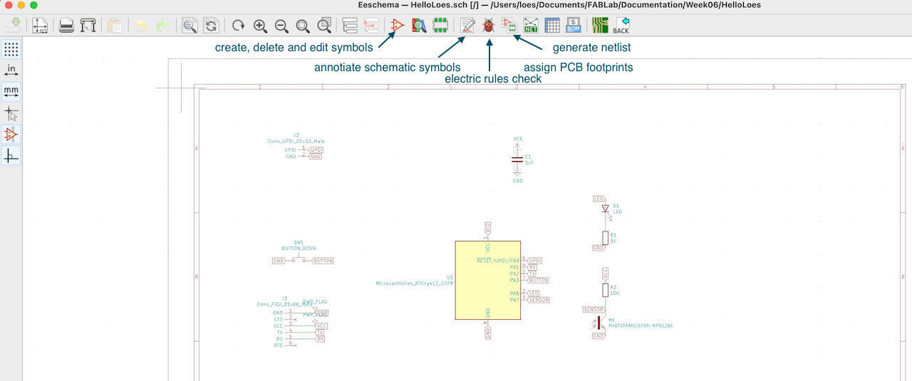
Now its time to check if there are no mistakes in your schematic which you can check with electric rules check, a beautiful lady bug in the top toolbar will guide you there.
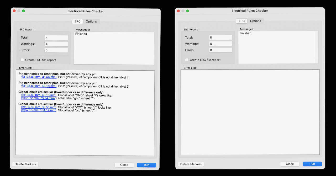
I found out that Kicad is picky when it comes to capitals so had to go back and change my labels. Probably it would not have made a difference but was happy to end up with a nice and empty error list.
Update PCB from Schematic
Next step is closing the schematic window and going to the PCB Layout editor, there you click on update pcb from schematic, then update PCB in the poo up screen and it should go to a black screen with a nest of your schematic..
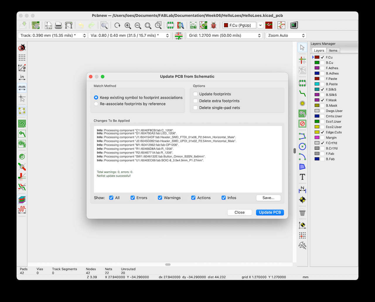
but mine didn’t - my screen stayed grey and seemingly unchanged
I first thought that i must have done something wrong so i retraced my steps, did it again.. restarted Kicad.. asked my fellow students for help and started to panic.. i was on the train to Adam to mill my board but complete stuck and time was ticking.
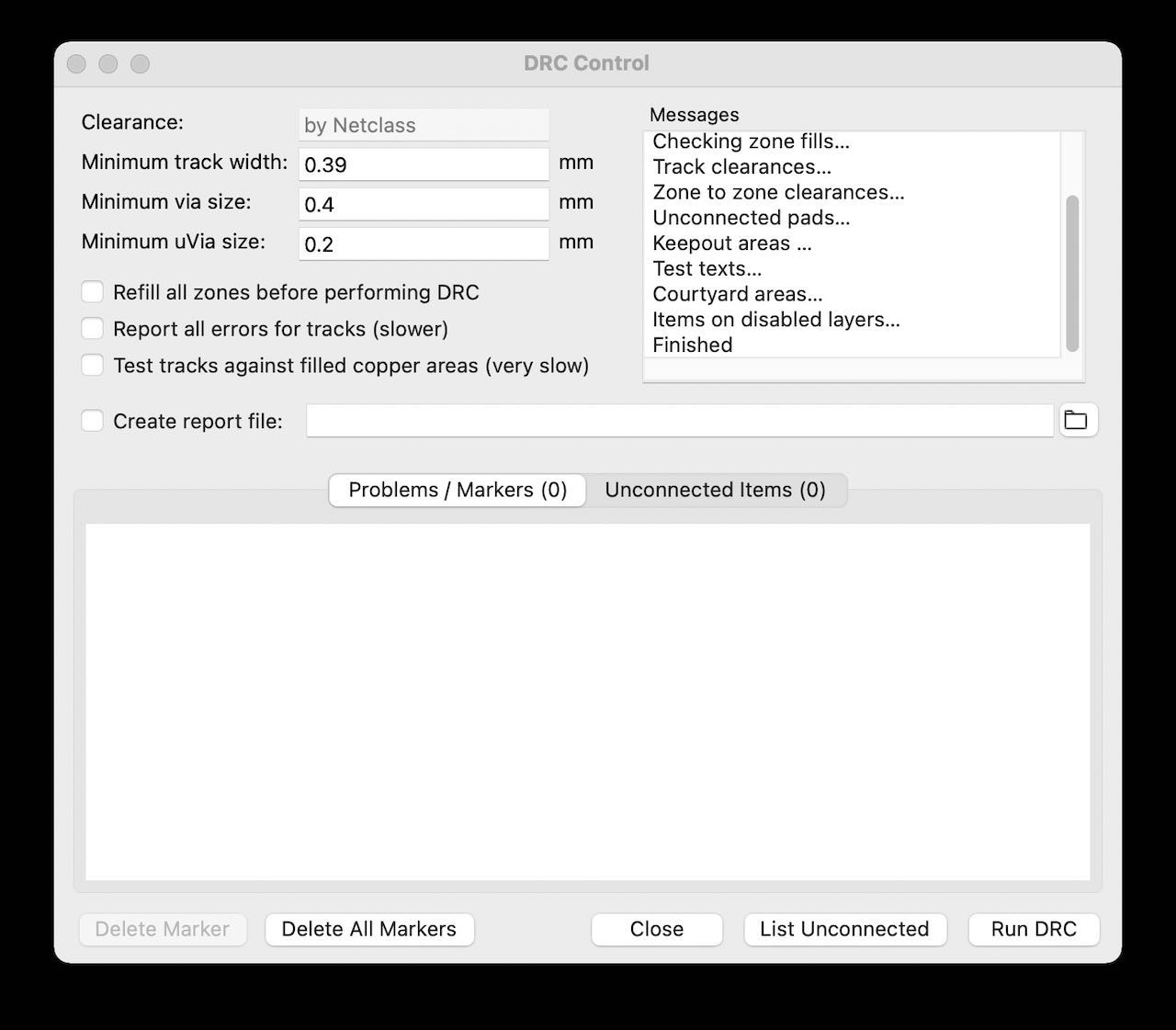
tried to see if there was an issue with the DRC control but also all good, it started to feel a bit strange.
After redoing everything together with Lucia and Nadieh online coaching me, google finally brought the answer with this link
it’s a bug and not a sweet lady bug.
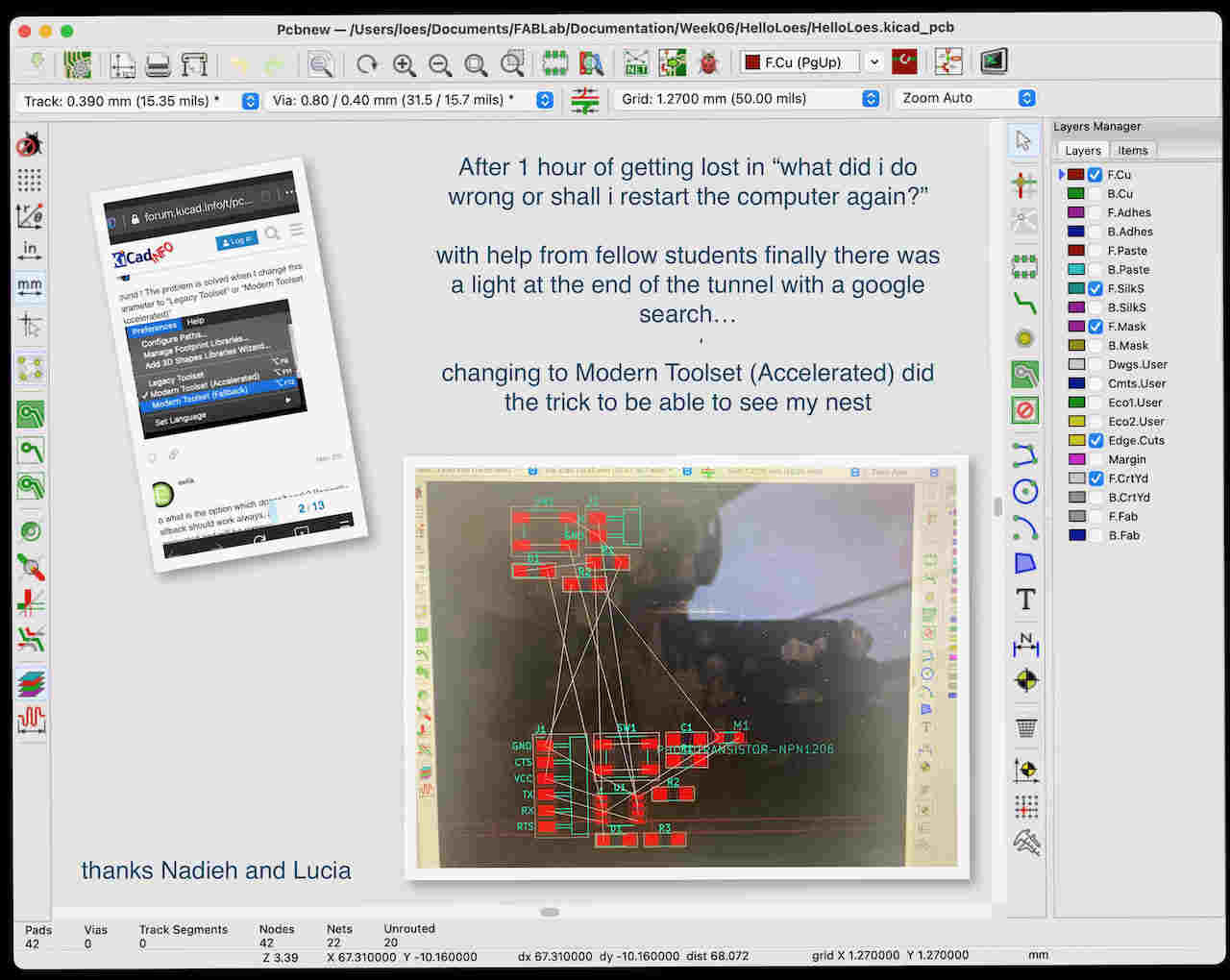
so i changed my preferences and was ready to finish my PCB.
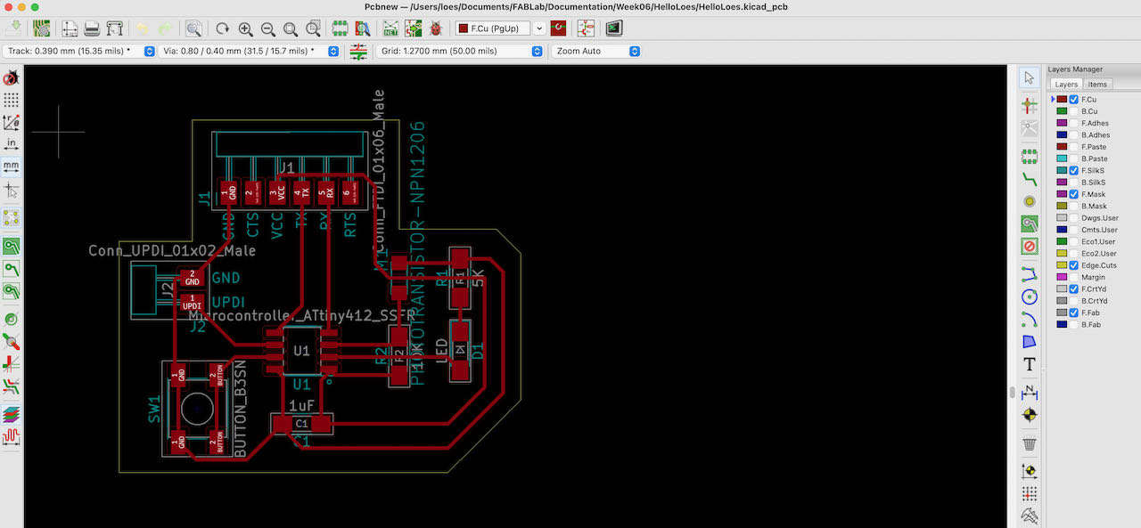
At first i struggled a lot with connecting all the traces till i calmed down and followed these steps:
- face the 2 connectors with there pins facing outside
- put the ATtiny in the middle since it has so many different connections
- turn and move the components around to have the least entanglements
- you can always let a trace pass underneath a resistor or diode
- start with connecting the signal traces
- then the VCC and at last the ground
When all done export the file as SVG make sure you click on the right layers and convert to Black and White.
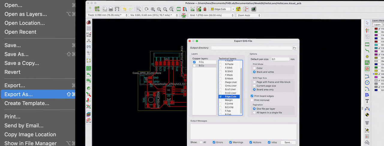
Last but not least I imported the exported SVG from Kicad into Gimp, since we figured out 2 weeks ago that PNG is actually a tiny bit more precise then SVG. The first time i exported the file i didn’t change anything which resulted in a traces and outline combined in one image, didn’t really make sense why Kicad would export it like this but due to time pressure i decided instead of finding out why i would find a solution.
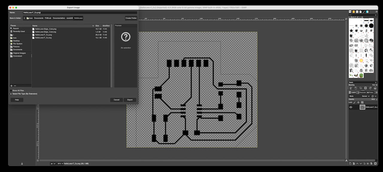
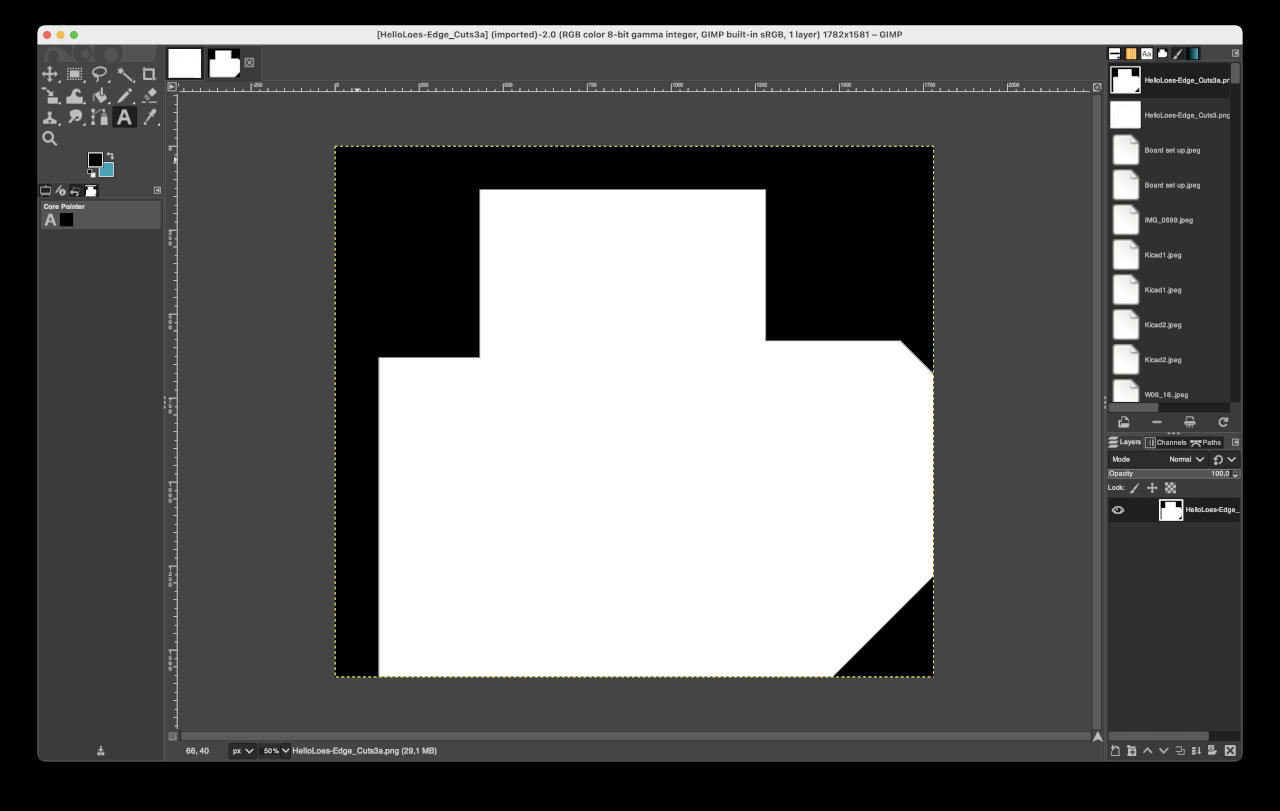
So i erased the outline in GIMP and added a white layer behind the traces because the first one i tried to import in gimp didn’t want to invert, it would just go all white. This did the trick, did the same with the outlines, inside white outside black, when i tried opposite mods couldn’t find the right outside and it would not close the line.
Soldering
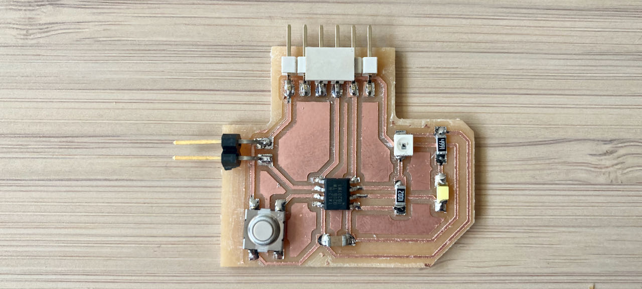
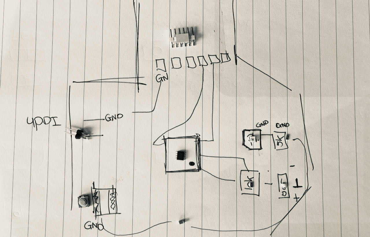
Gathering all the components first, made this list copied from the footprint list i made in Kicad:
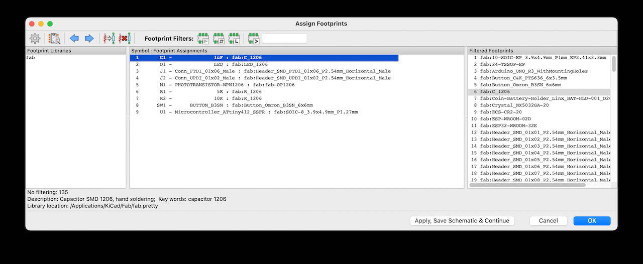
Components for the Hello Loes:
| Component name | label in de Waag | orientation sensitive? |
|---|---|---|
| Capacitor 1uF | C1uF | |
| LED | white LED for me | yes |
| PhotoTransistor - NPN1206 | Phototrans NPN PLCC-2 | yes |
| Button_B3SN | Switch 6x6 | yes |
| Conn_UPDI_01x02_Male | Conn Header | not really as long as the pins are right direction |
| Microcontroller_ATtiny412_SSFR | ATtiny 412 | yes |
| Conn_FTDI_01x06_Male | FPDI header | not really as long as the pins are right direction |
Then it was time to find out the orientations:
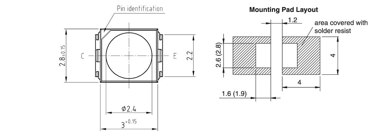
I was very happy the lab keeps the information and serial numbers in the same boxes as their components so i could google for information on the Phototransistor and found some documentation online which gave me the information that they have one cut of corner, the call it Pin identification, the opposite corner from the GND.
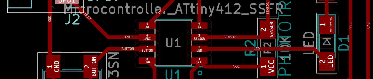
The ATTiny we also used 2 weeks ago so i remembered to look for the little dot or bump on one of the corners and yes.. it was there and to my surprise also on the layout editor in Kicad. That little blue one on the bottom in the center of the image.
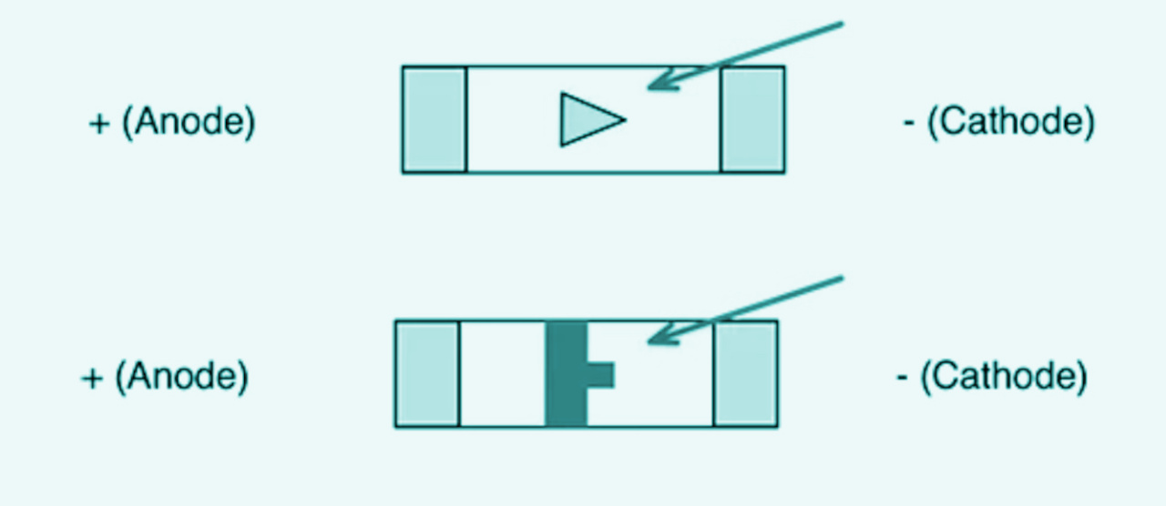
For the LED i could just search for LED SMD and that brought me to a very interesting website with some basic electronics information. The LED i choose had a green vertical line with a small dot on one side, like in the image below.
The orientation from the button was explained by Henk, there are some higher ridges underneath the switch which point to the same connections, so there is a 50% change you put it right without looking. Tempting but i looked and made a drawing to help me to solder them all the right way on.
Soldering this Hello board was compared to 2 weeks ago not very hard to do, the components were bigger and i made my life not to complicated by keeping my traces nice and big.
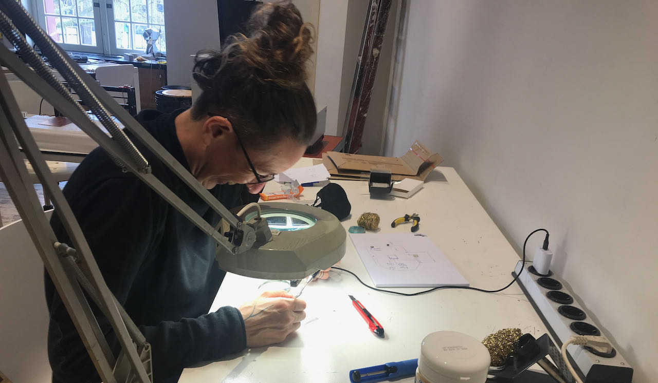
The end result, not so pretty but should be functional, tested the continuity with the multimeter so in 2 weeks time ready to program it.
- this was a crazy week for me since i was also working full time so honestly very happy i got this far as was able to understand so much already.
 - find a bit more time to work calmly and focused
- dive more into understanding the different components and electric flow with this tiny parts.