Week 07
Computer Controlled Machining
Group assignmentTest runout, alignment, speeds, feeds, and toolpaths for your machine
Individual assignment Make (design+mill+assemble) something big
Group assignment
 - Test runout, alignment, speeds, feeds, and toolpaths for your machine
 - understand the shop bot and Vcarve
 - get comfortable with the machine
Basic info
Speeds Chipload: how much the mill bites in (0.001 - 0.010 inches per minute) Cutdepth: roughly the diameter of the tool Step over : 1/2 the diameter of the mill (when you want finer then less)
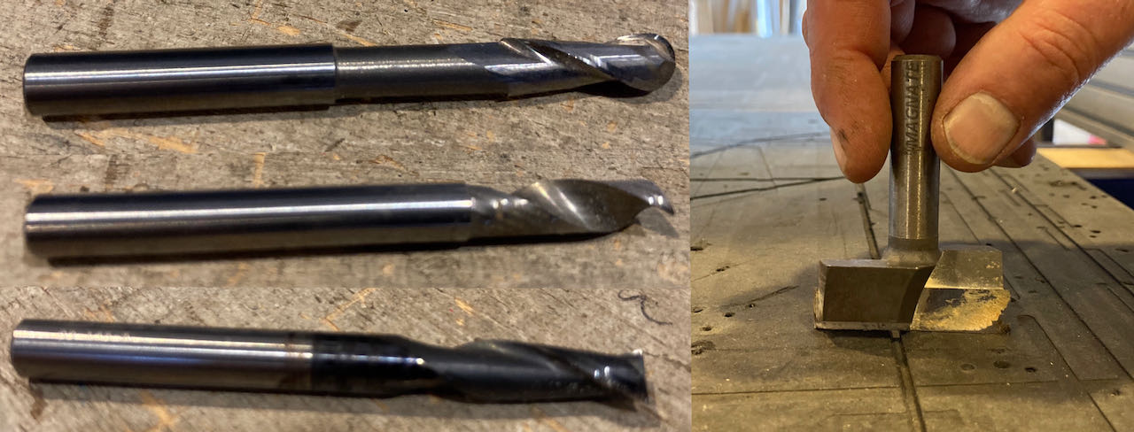
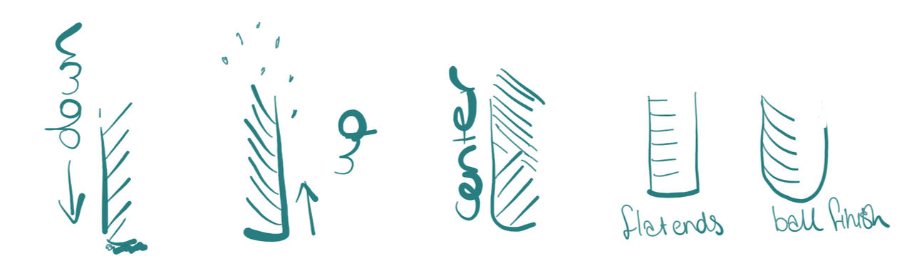
Flat end mills are smoother when using 3D, xyz milling Ball end mills can’t create smooth bottom surfaces.
Curving: means the mill only cuts partly through the stock (base material)
Curve can be bigger or smaller then the label on the tool, always measure the mill yourself.
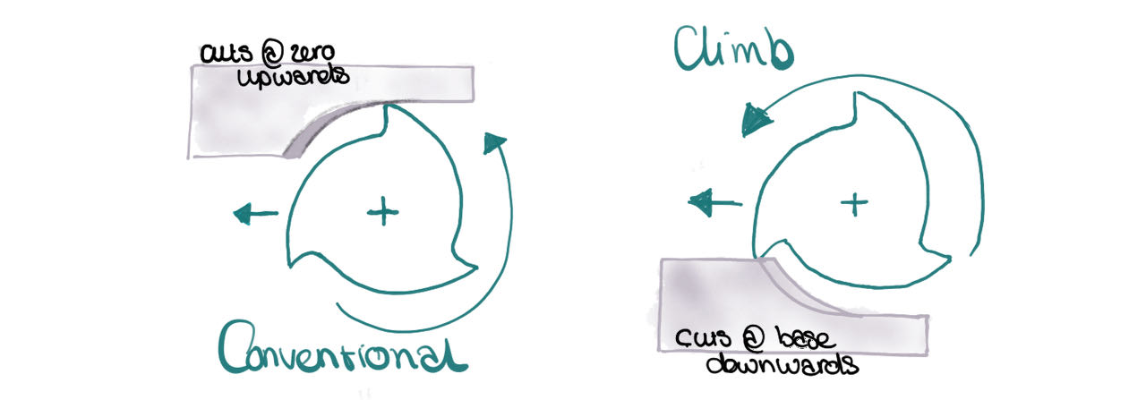
Conventional & climb as I found out in the milling week.
Trochodial milling which makes the mill go in a spiral form gives a more consistent cut.
Placement of milling line can be on the outside of your vectors, on the vectorline and inside the line.
Tabs are little pieces of wood (can be only a section of the thinckness) that you leave in the cut to prevent the cut out piece to move or even worse fly around.
Unioncut is another to prevent flying pieces, then you keep the bottom a bit attached - seems harder to remove then tabs
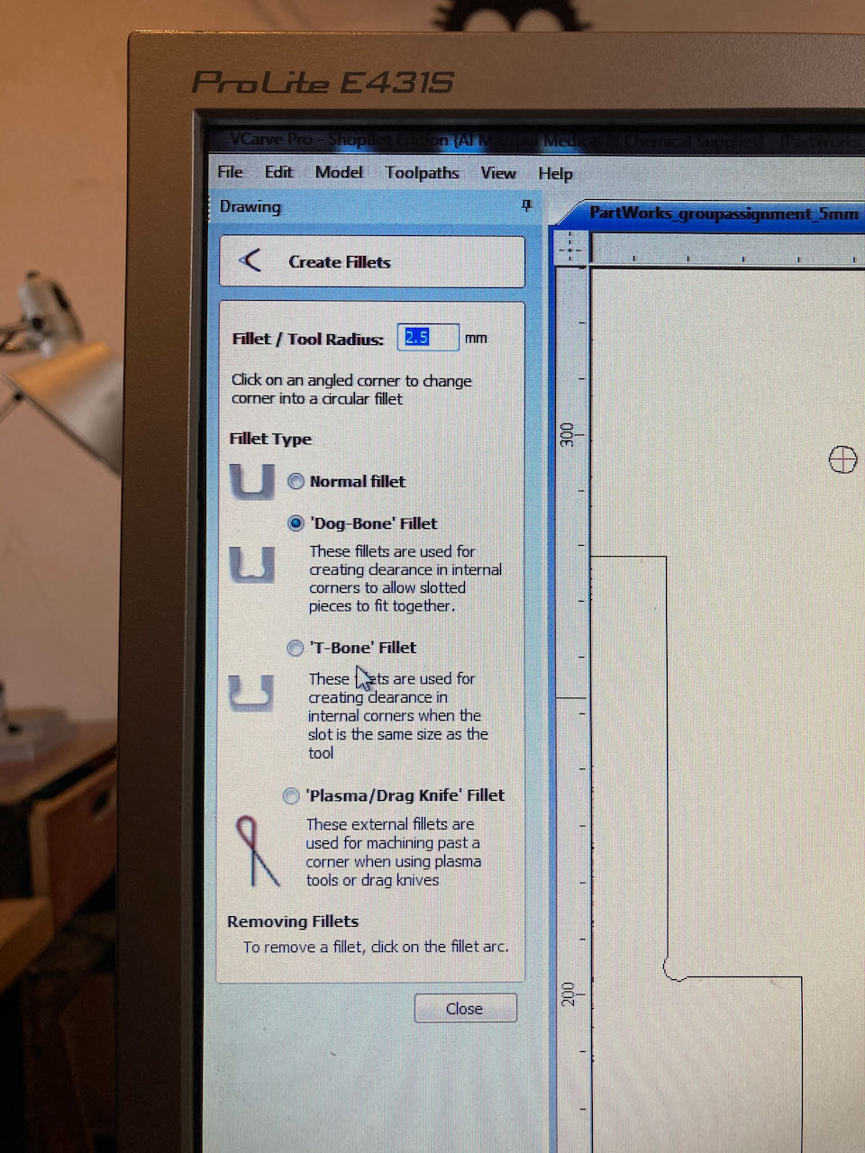
Dog & T-bones are ways to make sure you can cut out the corners since the mill is round and will not fit into the corner completly.
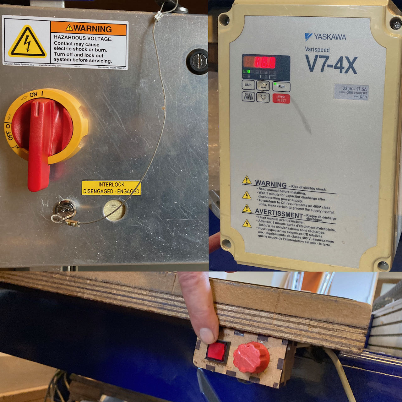
Safety rules
- make sure you know your environment, check exits, safety stops (below the groundplan of the room in the Waag)
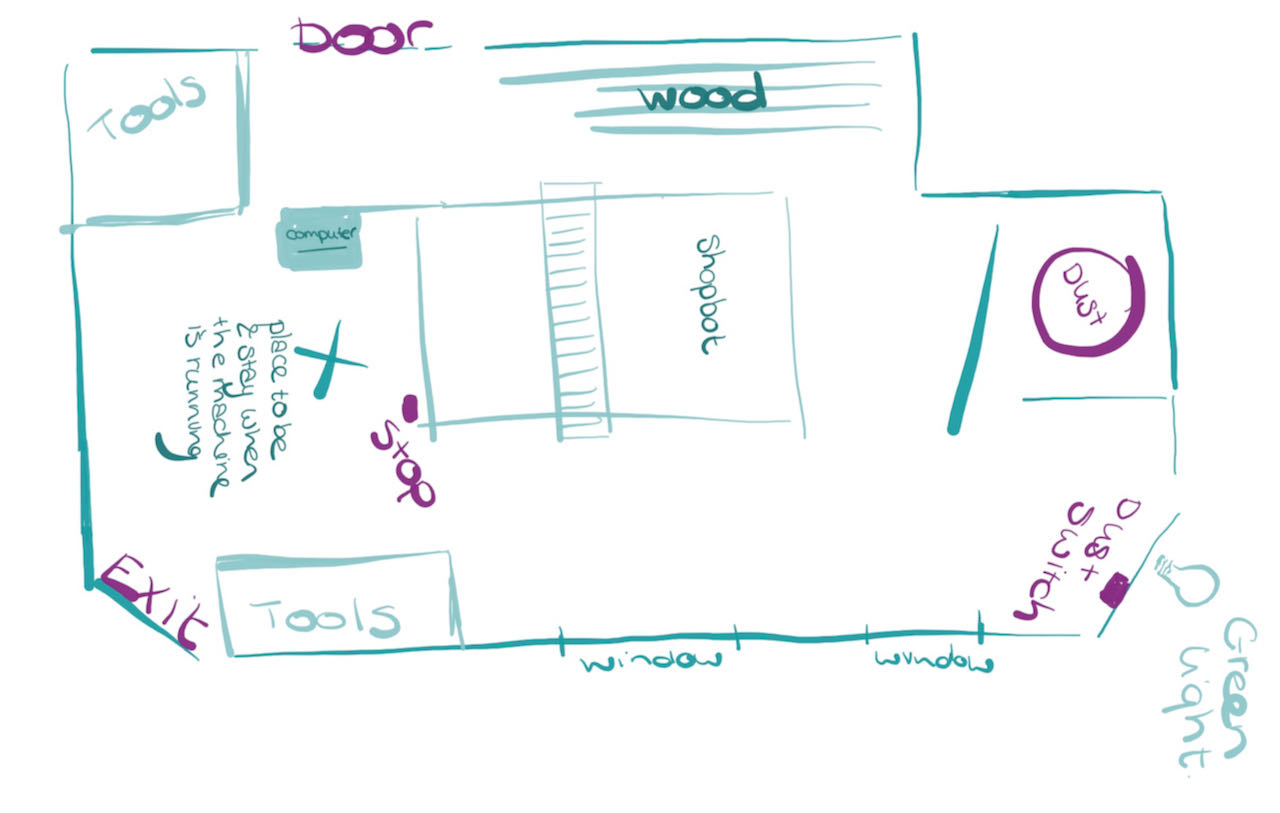
- no loose clothing or hair, no clutter around the machine.
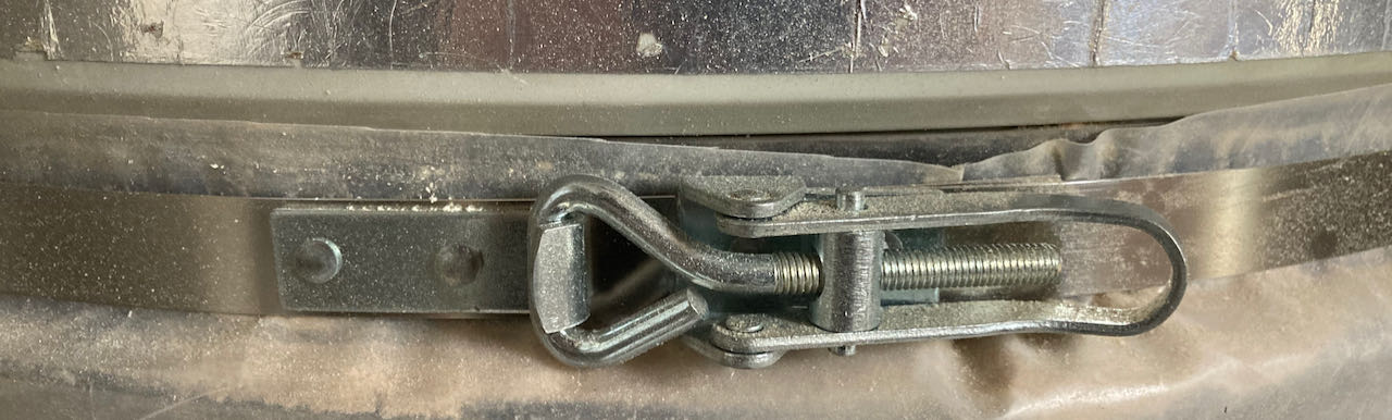
- check the dust collector bin, make sure you understand how to open it to be ble to throw it out when needed. (below the one in the Waag)
- measure your stock (plate)
Open Vcarve software
- Open your file, vCarve seems to prefer eps, dxf has some scaling issues sometimes.
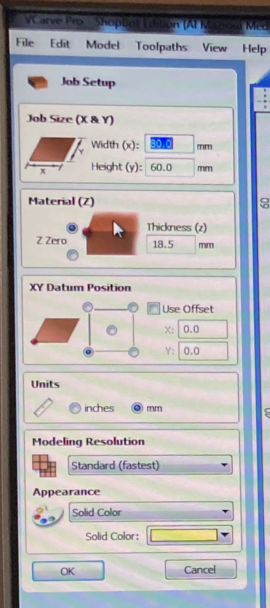
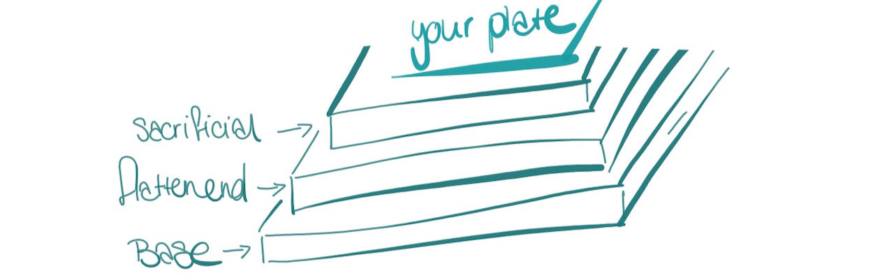
- Fill in stock measurements, don’t forget the placement of the origin. The thickness of the material should be the thickest one you measured but only that to prevent cutting to much in the sacrificial layer but still cutting through your design.
- Go to edit/move and check if there is really one vector not several on top of eachother as what happened to many of my fellow students.
- Adjust your file with dogbones and potential other adjustments that you need.
-
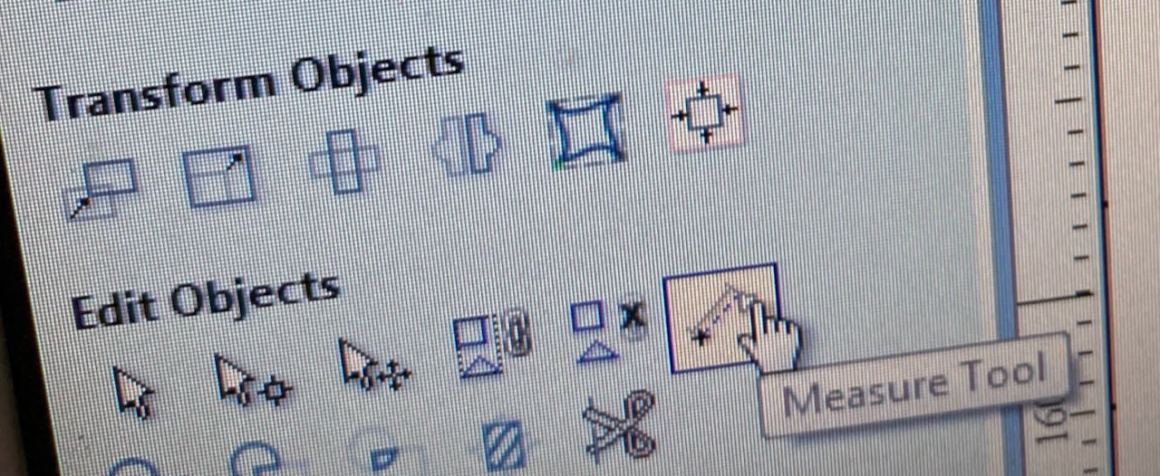
i would suggest to measure one of your paths to make sure nothing has gone wrong with importing
-
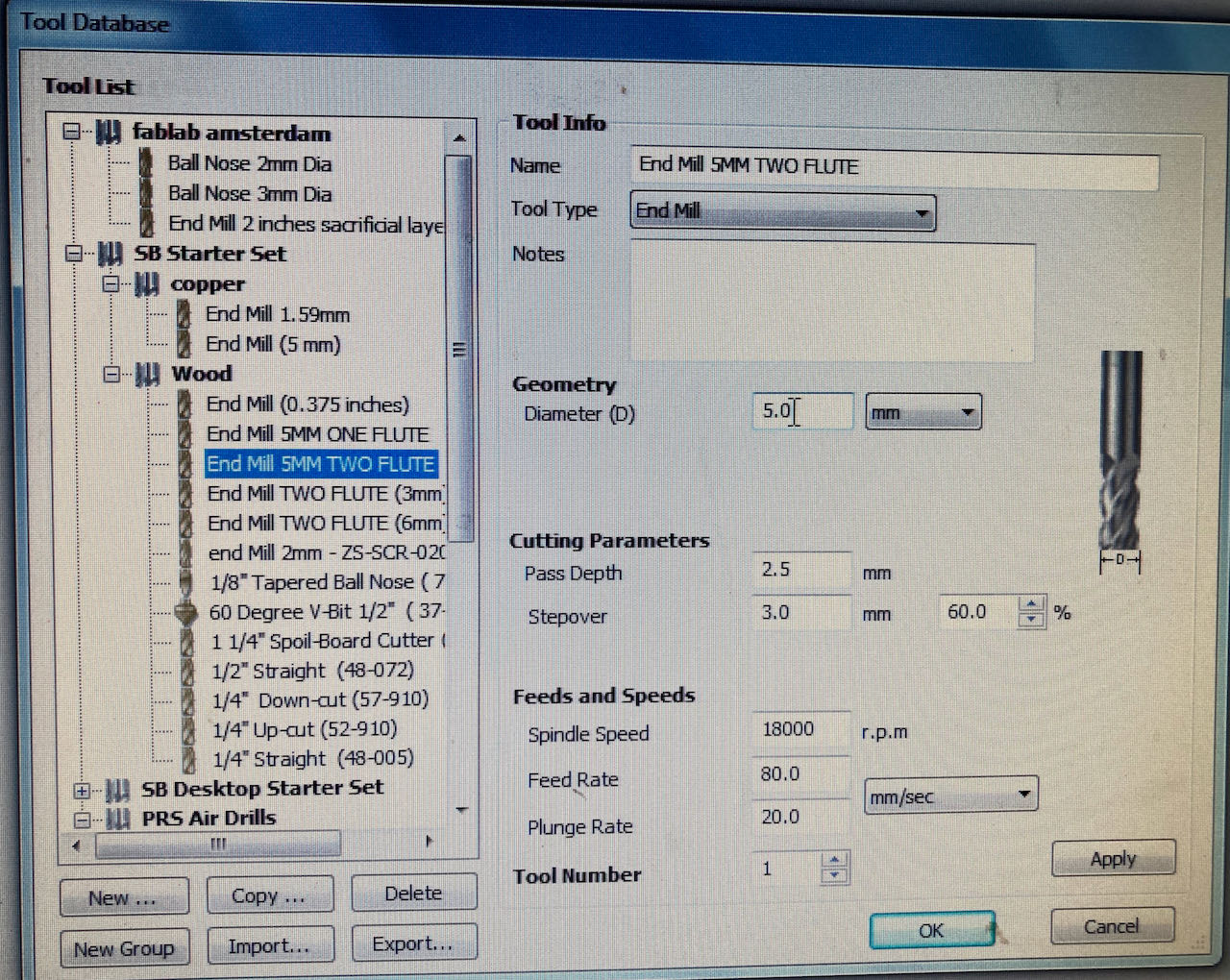
Fill in your milling bit specifications - in the Waag this is set for us using the 5mm - 2 flute.
-
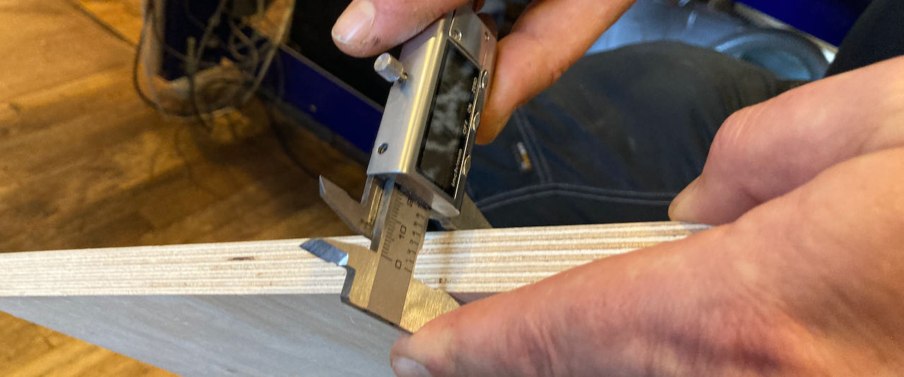
Measure the milling bit width to check (in our case the 5mm ended up being 4.9mm)
-
After some experimenting we ending up having an offset of -0.3mm in the paths to counter this missing 0.1 mm
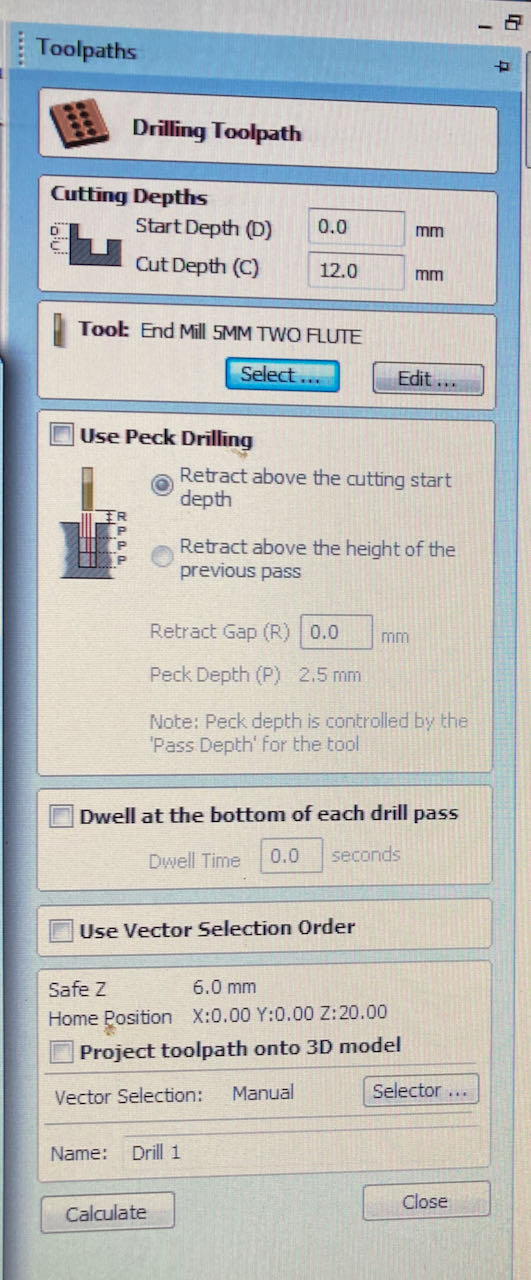
- First create your drilling toolpath.
- Click on the side at the toolpath tab, pin it to avoid annoying in and out popping
- Select all your drilling holes in the drawing
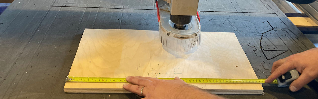
- Cut 3/4 of you material to keep some wood for the screw to hold on to (this picture was with the group assignment with 18mm plate)
-
Do this for all the paths you will have to create pockets and profiles
-
The profiles will have to cut through the material thus need tabs to avoid the flying around of wood.
-
Think about if you want the mill to cut on the in or outside, profiles are logicly outside.
-
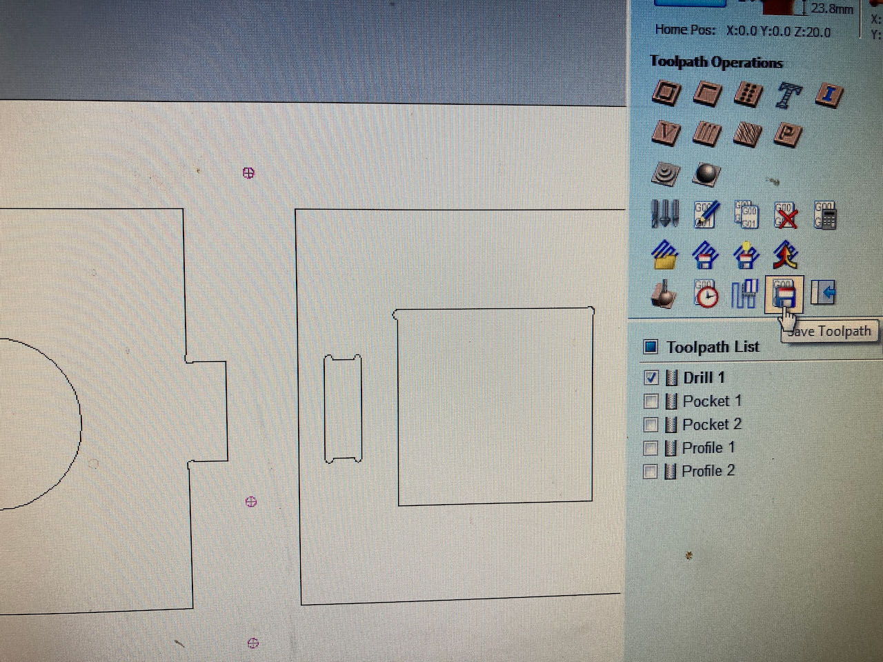
Gather all the same toolpath operations in a layer together so you can arranged them in order.
-
Right clicking on the toolpaths will give you the option to edit, don’t forget to recalculate them.
-
Make sure the paths are in the right order, (first drilling, then all the other thinks and last the outside profiles) if not then adjust them with the blue arrows.
-
Select by ticking the box in front of it, the toolpath you wanna save (first only the drilling) and save to file
-
Deselect the drilling toolpath, select all the others and save to another file.
prepare the machine
- check the sacrificial layer for bumbs and screws left by the ones before you, sand if needed (only the bumbs) otherwise you will create a wavy surface.
- place your stock on the sacrificial layer
- Measure the milling bit width to check (in our case the 5mm ended up being 4.9mm)
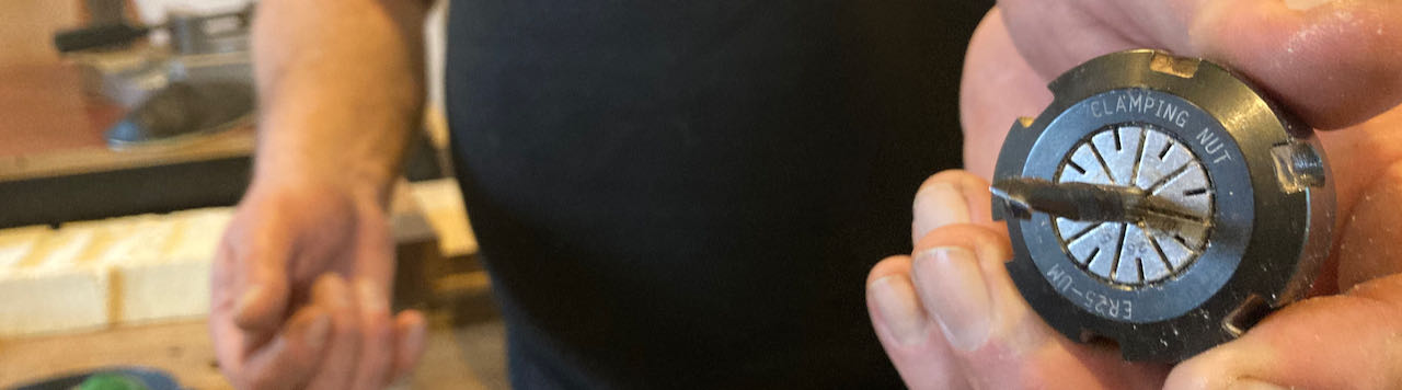
- Put the collid in the nut
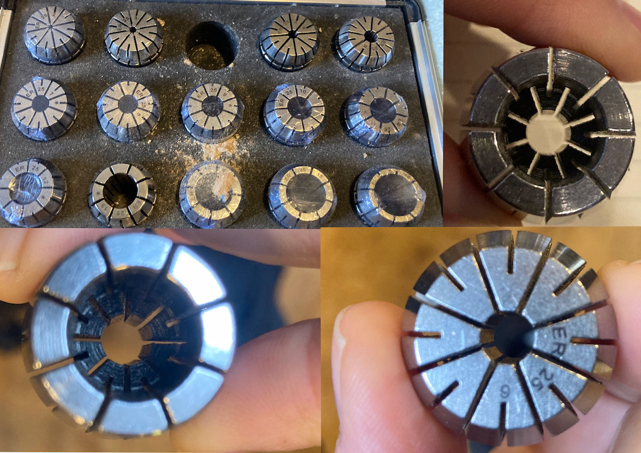
- Insert the mill in the nut - measure it, minimum 2 cm should stick out, check if it touches the edge in the collid.
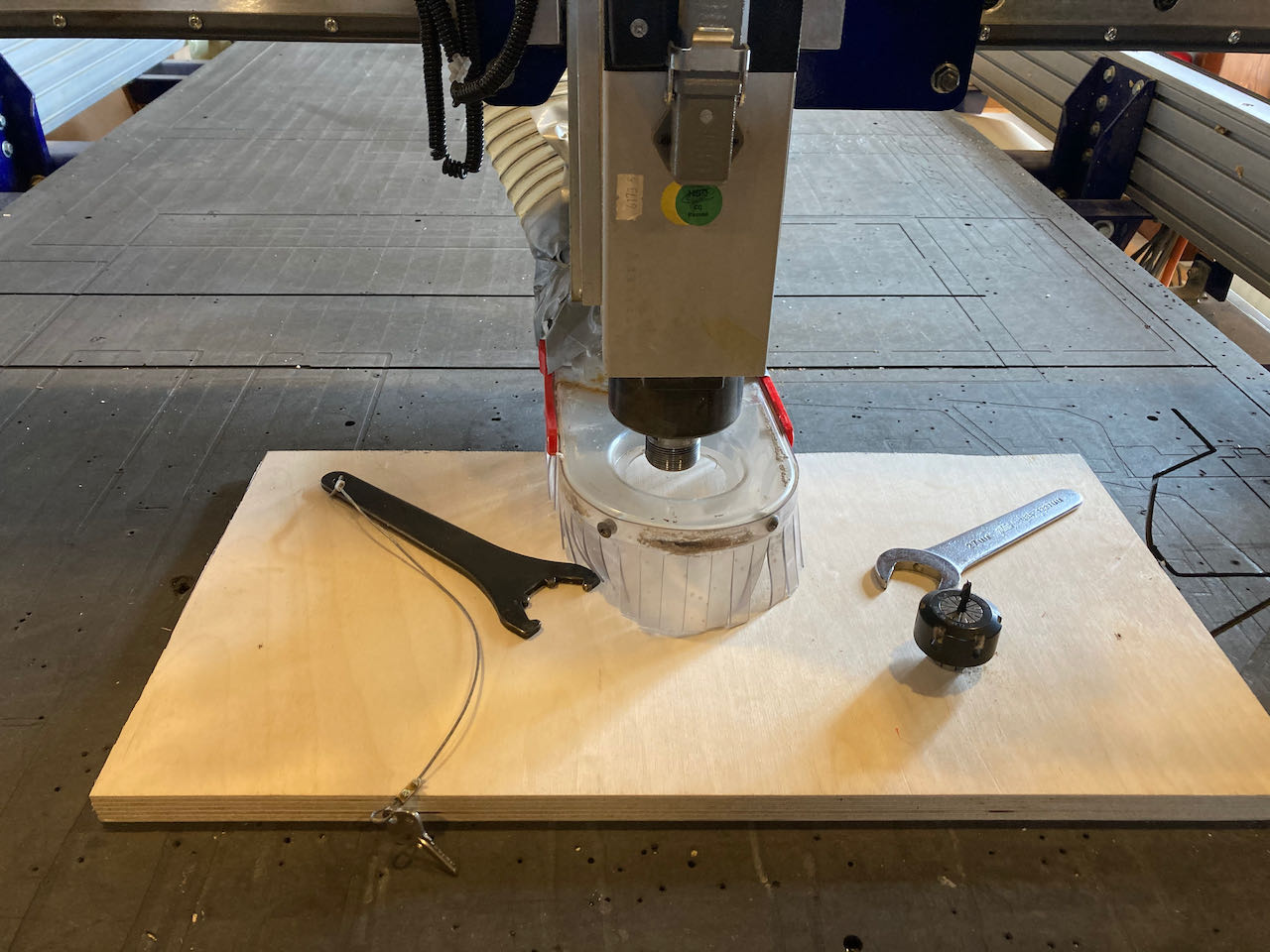
- Lower the skirt by undoing the wingbit
- Put the nut in the spindle with 2 english key & wrench (one has the key from the machine attached to it)
- Tight but you should still be able to undo it later
- Clean the working space, make sure you know the exits and nothing is in the way of the machine.
- Switch on the dust collectors power in the corner
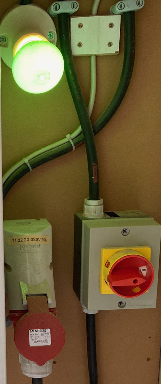
- Switch the machine on (only the red knob on the side of the shopbot the rest is for when you are ready to mill)
Open shopbot software
-
Check the direction off your wooden plate on the machine (think about the direction of your design)
-
XY home- the machine will make an alarm sound and moves to the origin of the machine -
Adjust it with
→ ↑ ↓ ←to the exact corner of you plate. -
If needed you can move Z down
pg up - pg downto make it easier visually -
Take a picture of the values just in case because the numbers got to zero after the next step.
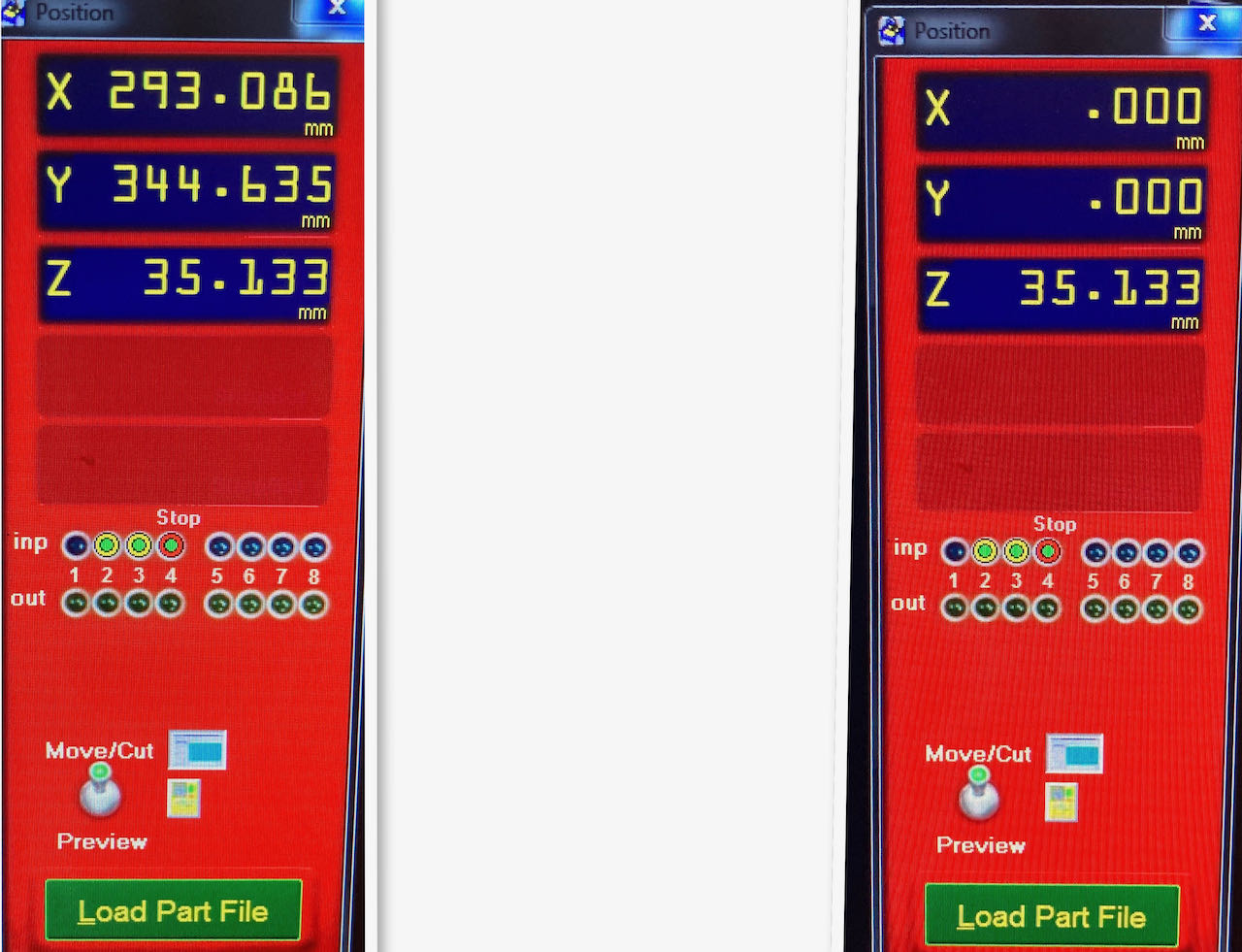
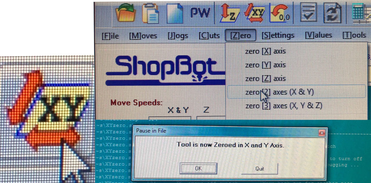
- Go in the top menu to
zero-zero-XY-azis - Popup screen with the message ‘tool is now Zeroed in X and Y axis will appear
- Press K for keyboard
- Move the arm with
→ ↑ ↓ ←to a position where you think the plate will be the flattest, for sure not the corners, probably somewhere towards center.
In case of an airrun: Put an extra thick plate in between your plate and the mill so that you can set up for an air test run.
-
→ ↑ ↓ ←andpg down - pg upare the single ones, the one from the numeric triggers something else in Keyboard which i quickly clicked away (forgot to take a picture but easy to redo this) -
Put the metal small plate underneath the mill exactly in center of the mill, make sure there is no dust, tap it against the mill to check if the green dots reacts (otherwise it will keep on going down because it will not create a closed circuit)
-
Z axis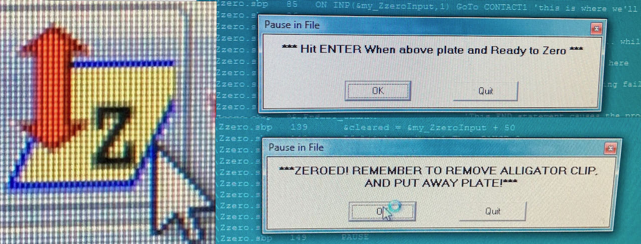
-
When confirming the first pop up screen the machine will sound an alarm and move the mill down to the metal plate, keep your hand on the space bar to pause in case it goes wrong.
-
Confirm the second pop up and remove the alligator clip which is apparently how they call the little metal plate.
-
Press K for keyboard - with
pg upmove the mill a bit higher so you can remove the alligator.
In case of an airrun: after the run make sure you set the real Z axis again.
- Put the milling on with the key on the side, also the dust collector on the frontside of the shopbot
-
adjust the speed to what you’ve put in Vcarve.
-
No more moving from your place
-
open
Pfilefind the drilling file first -
Pop up
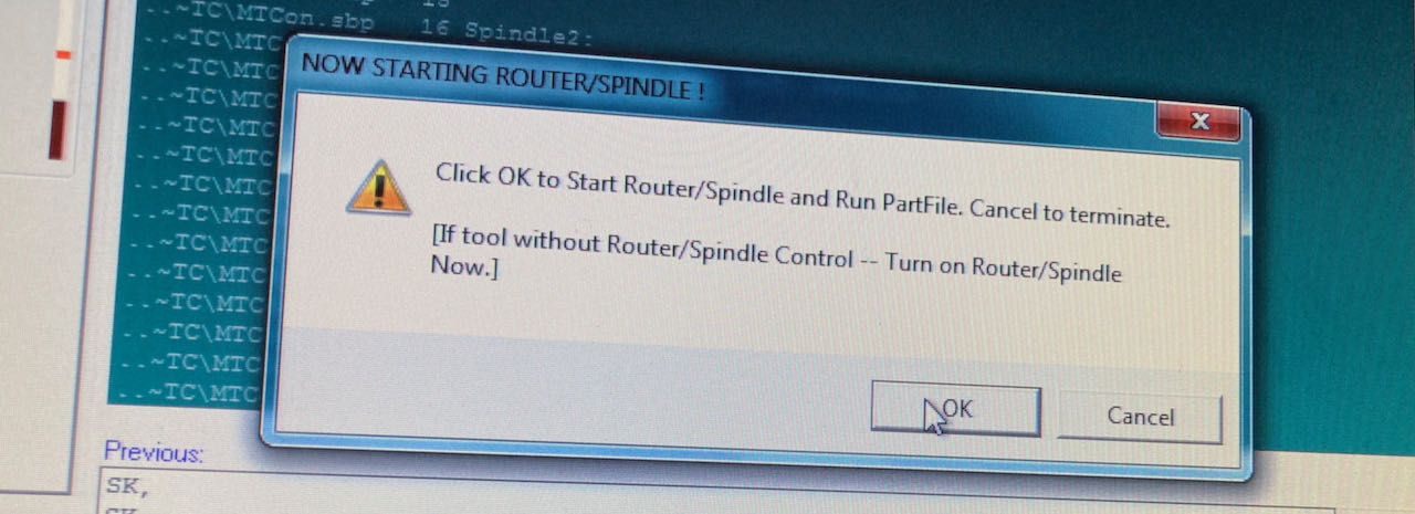
-
Okand hands on the spacebar - the machine will sound a alarm and start milling the drilling holes -
When finished switch the mill and dustcollector on the machine off (keep the big red knob on)
-
Screw the plate down into the sacrificial layer, nice and tight.
-
Set the Zaxis again, since it may have moved down a fraction
-
when finished run the ‘real’ file same procedure as the drilling file with your hands on the spacebar
Safety
If your mill hits a screw or anything else metal it can create a little spark which will be sucked into the dust collector bag being fed with fresh air potentially creating a fire sea. So if you see a spark, press spacebar to pause, go to the dust collector switch it off, removed the bag, keep it airtight and if needed throw it out of the window. If it only smoulders then you can go down the stairs with it.
Finding group assignment
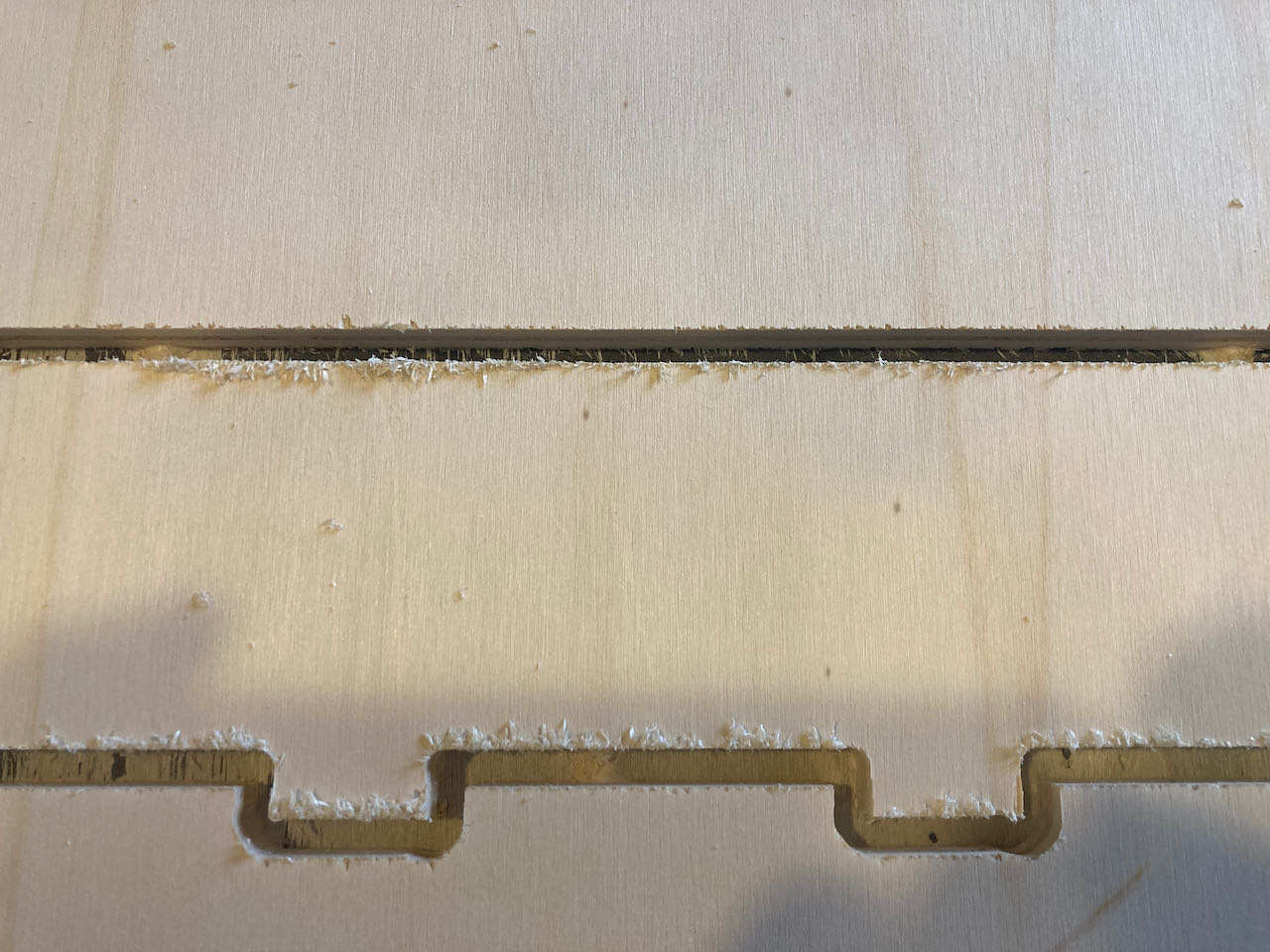
Our design came out a bit rough, apparently the mill was old, but not only that the design was not the same size as what the traces were that we gave the machine. The cutouts were less then what we expected and the profiles seemed to big. We measured the mill again and realized it’s not 5mm but only 4.9 thus not cutting away the 5mm that we expected. So thats when Henk told us we could us offset to avoid this or if we want to we could also tell the machine the mill is only 4.9 instead of 5mm which i maybe the road i will travel next time.
individual assignment
- Make (design+mill+assemble) something big
- make a desktop stand or something else?
- understand the machine
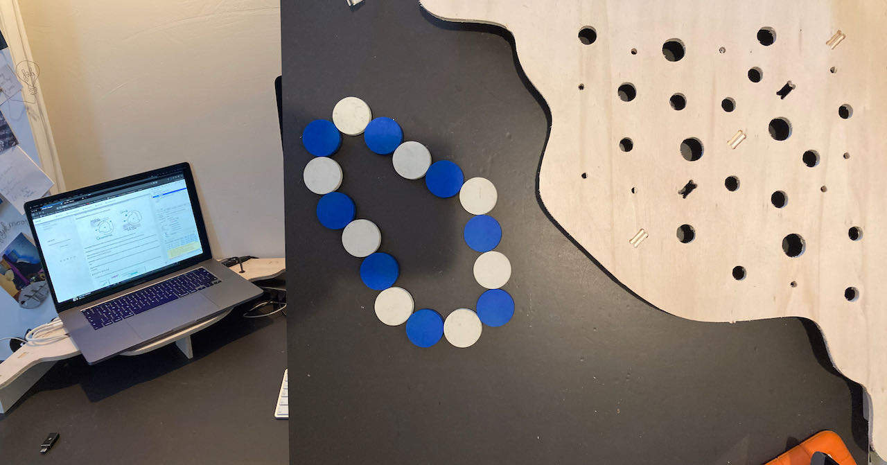
Something big sounds exiting if you take the time to figure out what you want.. in retrospectief i would have made different choices although having my laptop on an elevation on my desk is a nice bonus. It was a real learning from your mistakes week.
File prep
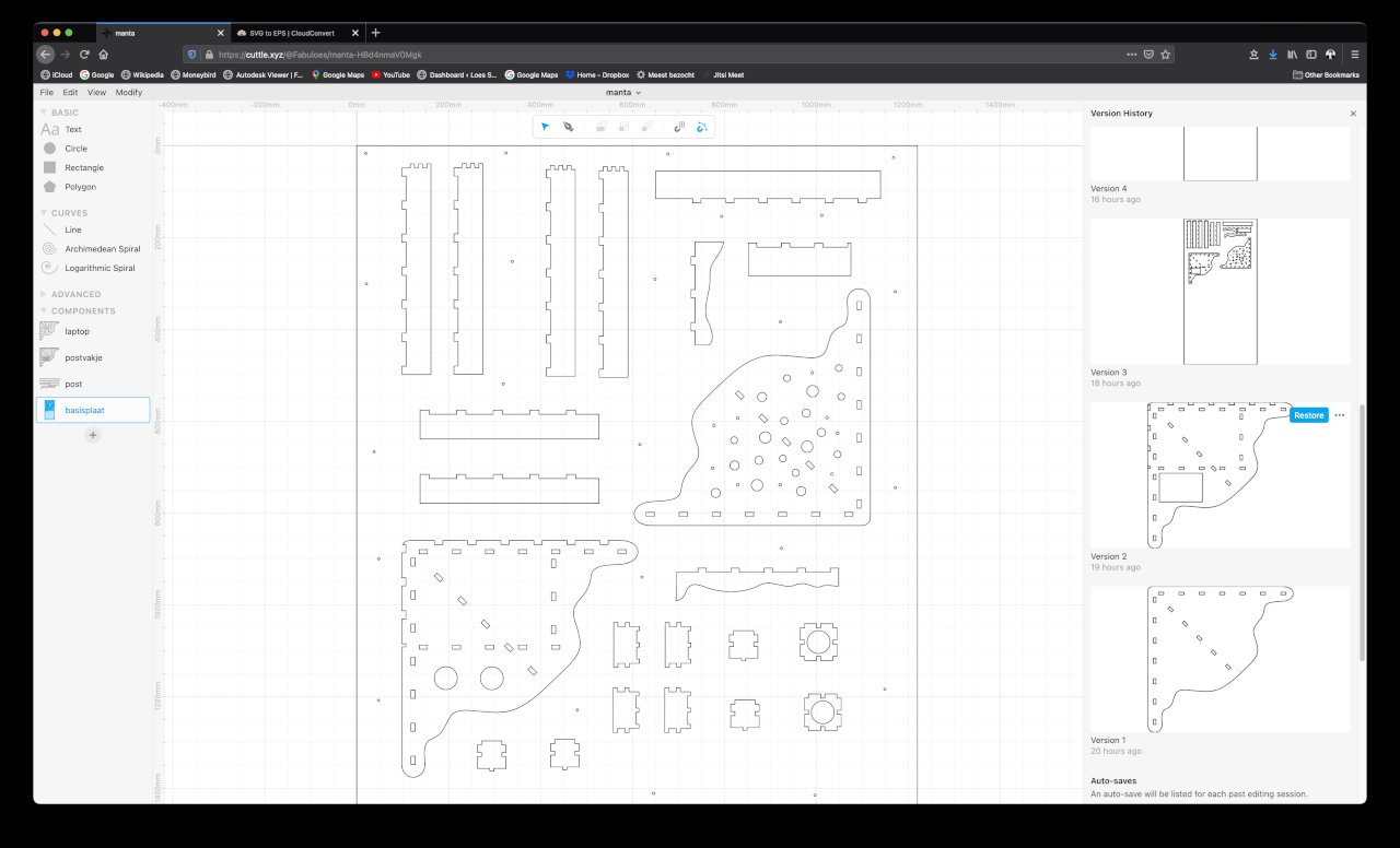
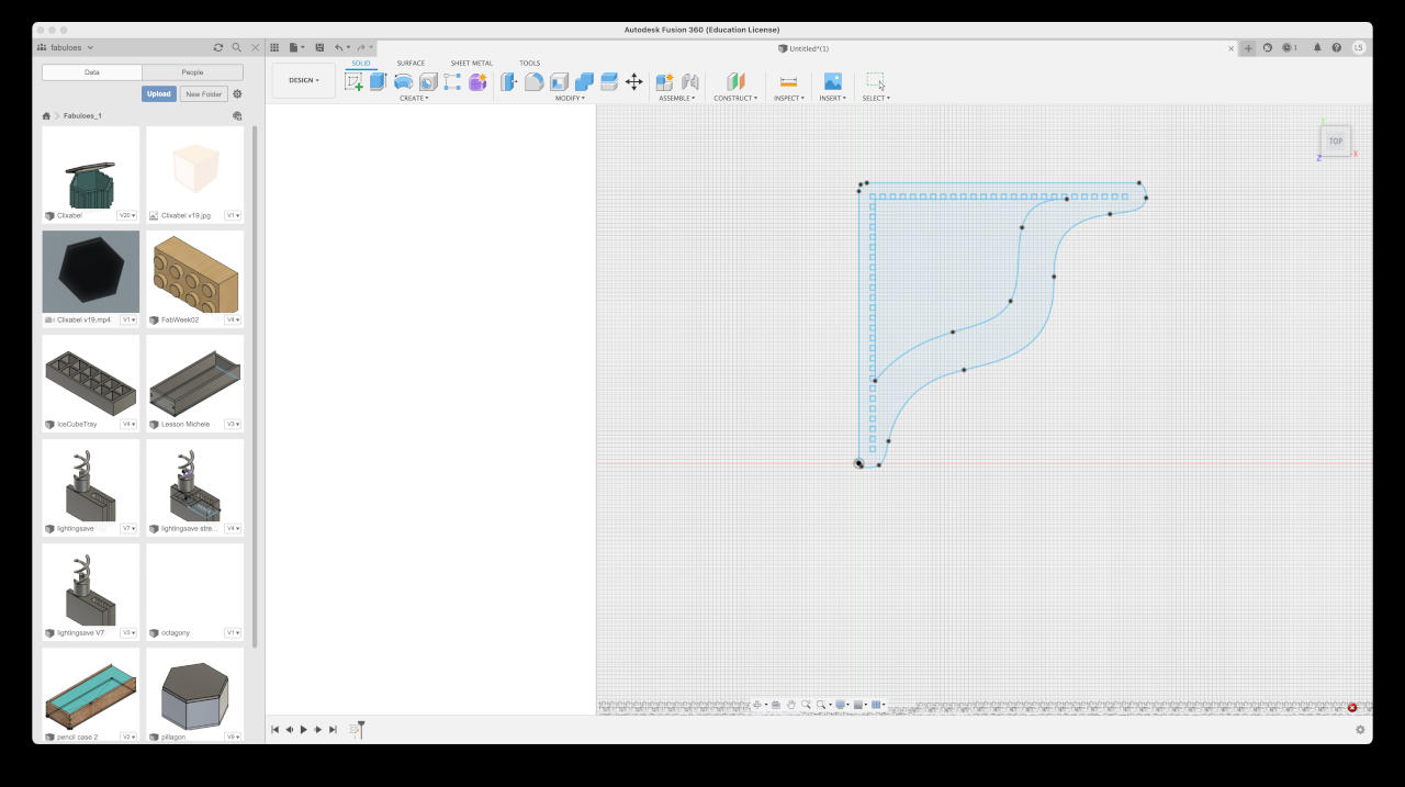
At first i really wanted to make my design in Fushion but after getting stuck with the simplest things and the software crashing 2 times i was doubting my choice. Then all the feedback came dripping in from fellow students working with Fushion and getting strange lines or missing vectors thus having to import it into illustrator before being able to use it in VCarve. Since i was again (hopefully the last week work interfered so much with the fun) under time pressure i decided to play save and work with Cuttle again since i knew from the laser cutting week the files were stable and doing what they should do although they are SVG so i do need to convert them into EPS which seems easy. I even used an online convertor for converting the SVG into EPS.
My cuttle design:
The start in Fushion before i gave up:
With the files in all kinds of formats (PDF,EPS, PNG & SVG) on the stick i went to the Waag. Also made a little drawing to remind myself of what to do.
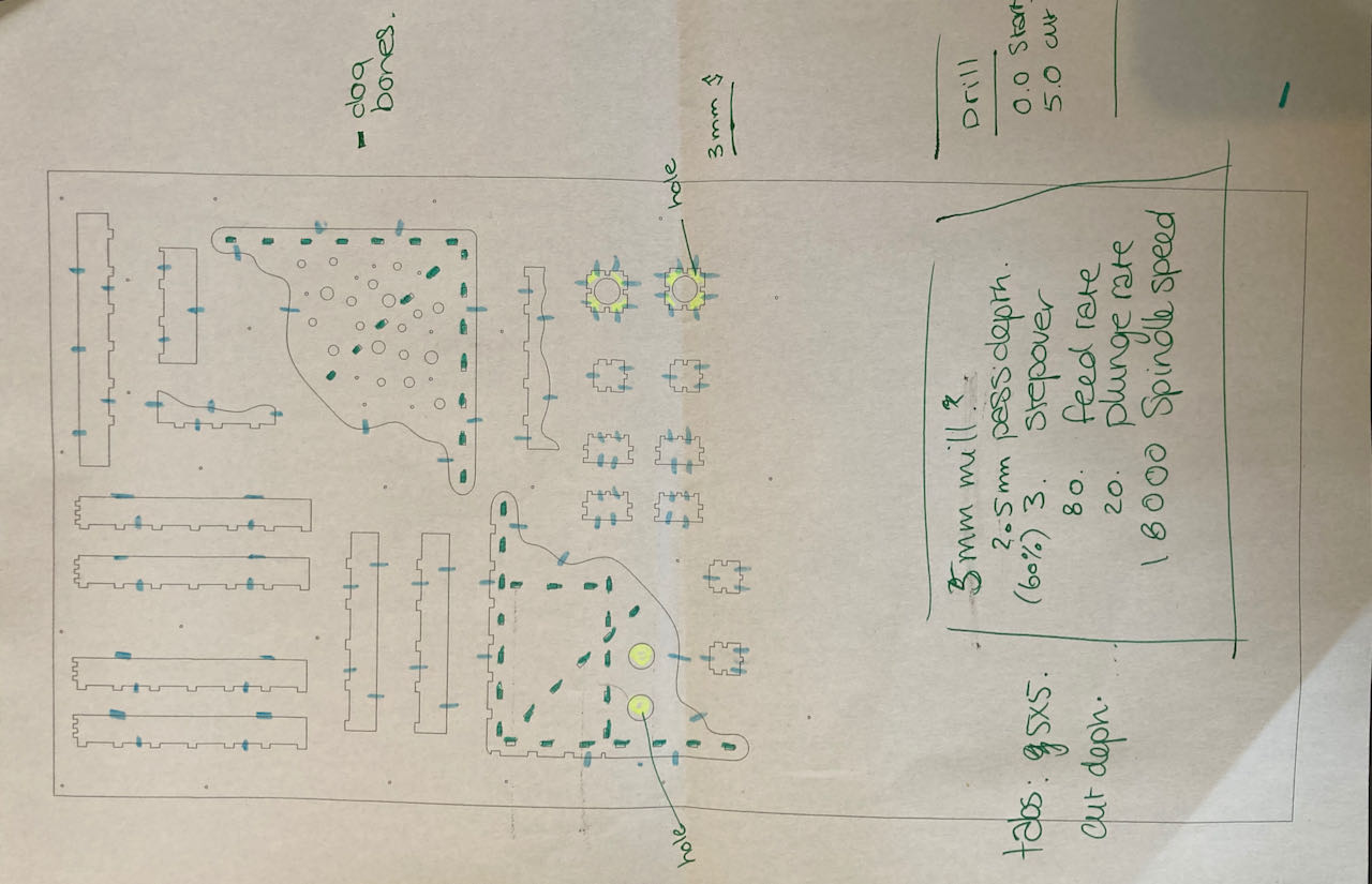
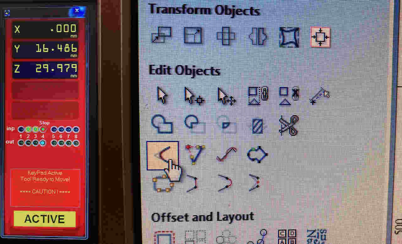
Of course i followed all the steps mentioned above in VCarve and realize i didn’t archive the placement of the fillet (dog bones) tool, so here it is below for future reference.
used settings in Vcarve: in detail mentioned in the group assignment above.
-
drilling path:
- cut depth: 6 mm
-
other paths:
- end mill 5mm 2flute
- pass depth 2.5
- step over 60%
- spindle speed 18000
- feet rate 80 mm/sec
- plunge rate 20 mm/sec
- OFFSET of 0.3mm
A small video of my toolpaths
When Michelle and myself tried to put the plate on we realized it was very curved, so decided to put it on with the pointing up corner to the bottom. When putting the drill holes in this went dramatically wrong. the mill went through the part of the plate that was rounded, maybe next time stick it down?
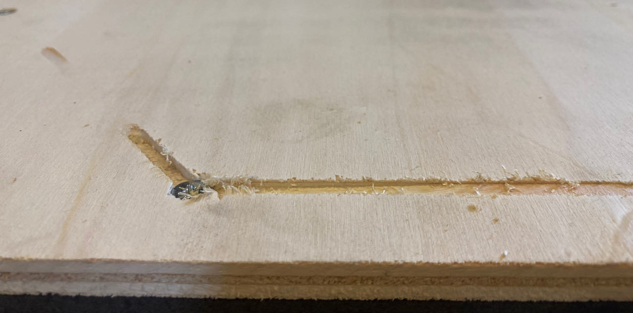
Luckily enough it was not so much in my design and it seems like by the looks of the sacrificial plate that we didn’t go through the plate to much. I choose 9.25 thickness for my material which was the thickest part i measured on my plate.
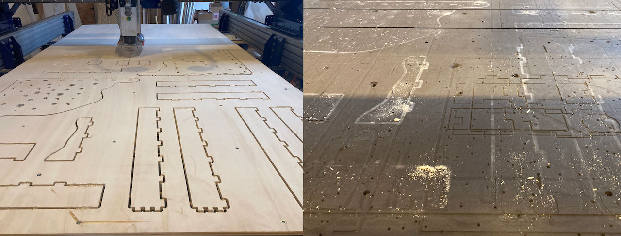
But there were still parts it didn’t go all the way through, Henk thinks this is because of a wavy sacrificial layer due to sanding to clean out screw bumbs.
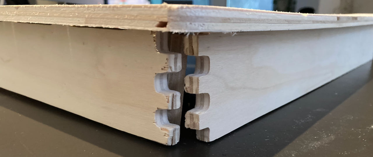
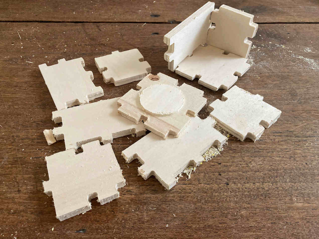
This is the part of my design that i could actually use. So many things were just off, mainly because of bad design but also trying to make things on a machine thats not made for this, like my little boxes, they are so rounded, i’ve should have made them with thinner wood on the lasercutter.
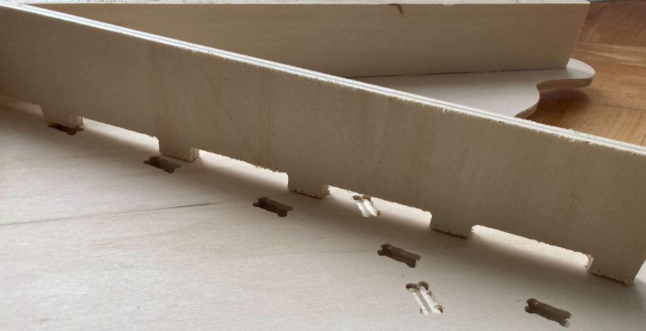
I should have continued in Fushion because most of my failures in my final result are from bad design.. only working in 2D to create a 3D shape needs a better trained brain then mine. I ended up making stupid mistakes like forgetting about the thickness of the material and by the looks of it moving finger joints on a vertical base.
What i did wrong was not having a fitted 3D design and make it flat but thought i would go directly from the 2D version and do the transfer from 3D in my brain and on paper.. but made to many mistakes with placement of fingerjoints and size of holes.. but i still use it as a computerstand, it works fine just not fitting as smooth as it could have if my design was better.
- fun week, although the Shopbot is very intimidating but happy i got to understand the machine better and able to make it do what i want it to do, if only my design skills would get better fast :)
 - use 3D software when making something in 3D - understand the limitation of the machine better before designing. In dutch we say : meten is weten.. measuring is knowledge..
 - Figure put how to work with Fushion, watch another tutorial and take the time.