the Tasks for this week is to
- Test more than one software for cad design
- Demonstrate and describe processes used in modelling with 2D and 3D software
- Modell experimental objects/part of a possible project in 2D and 3D software Model (raster, vector, 2D, 3D, render, animate, simulate, …) a possible final project, compress your images and videos, and post it on your class page
in this week assignment first we need to evaluate CAD design software, to do that i chosed two software wisch is freeCAD and Onshape
FreeCAD

FreeCAD is designed to fit a wide range of uses including product design, mechanical engineering and architecture. Whether you are a hobbyist, a programmer, an experienced CAD user, a student or a teacher, you will feel right at home with FreeCAD.
Download
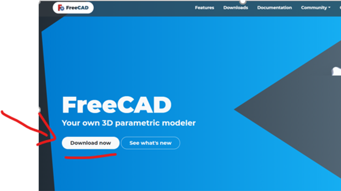
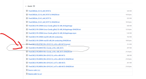
to download the software click here, then click download and choose the version according to your operation system, for me iam using windows 64-bit
Home screen
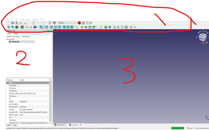
FreeCAD home screen can be divided into 3 sections.
- Tool bar
In the tool bar , you can create planes, transform into 3D, use bevel processing to create models.
- Combo view task
In the compo view, you can check the hierarchy for the objects and effects you created in the tool bar.
- Work area
In the work area, you can check how the model looks in 3D and 2D
Workbench
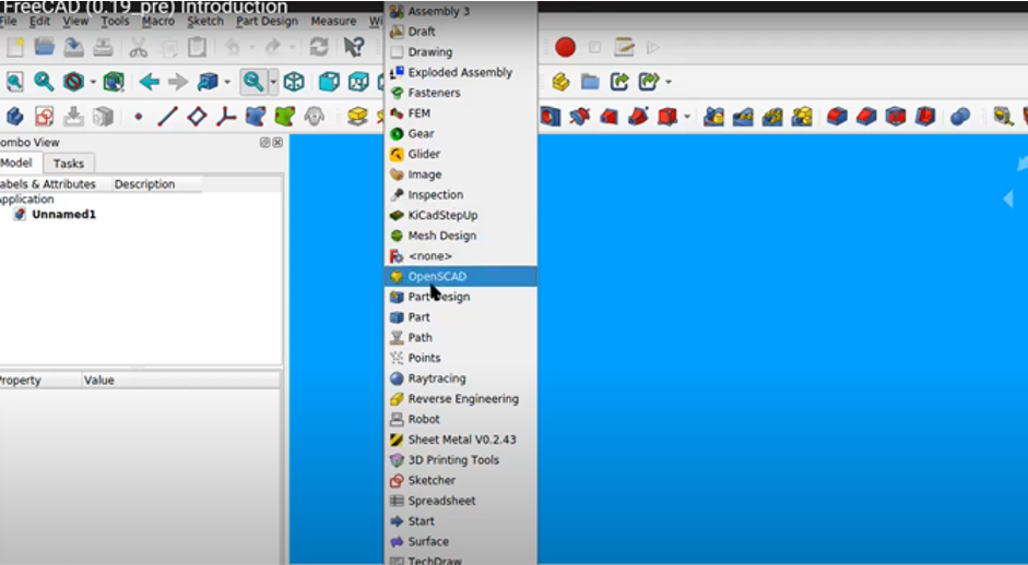
FreeCAD is based on workbench or workspace, i will not go through them all i will explain the one to use them
- Sketcher Workbench
is used to create 2D geometries intended for use in the PartDesign Workbench, Arch Workbench, and other workbenches.
- Part Design
is working with a constraint based system. This means that we have to first create our shapes and then restrict them. First we want to constraint the position of our rectangle. We select the two outer points and then the center.
- Spreadsheet Workbench.
This workbench allows you to create spreadsheets such as those made with Excel or LibreOffice directly in FreeCAD. These spreadsheets can then be populated with data extracted from your model, and can also perform a series of calculations between values.
- TechDraw Workbench
is used to produce basic technical drawings from 3D models created with another workbench such as Part, PartDesign, or Arch, or imported from other applications.
Getting Started
when you start a new project you will see this combo view task that tell you what you can do at the moment
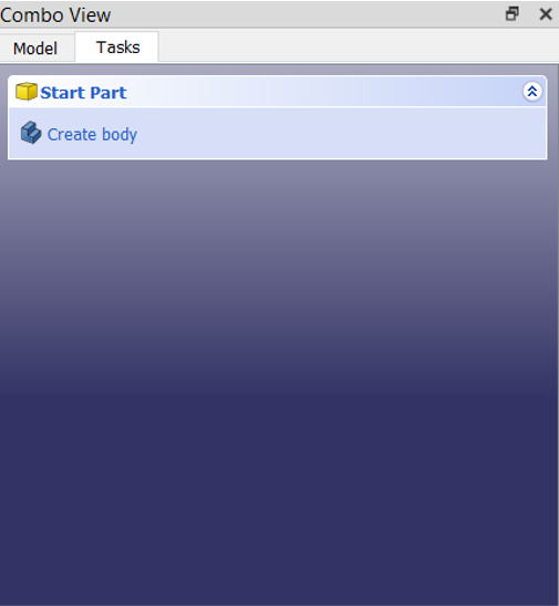
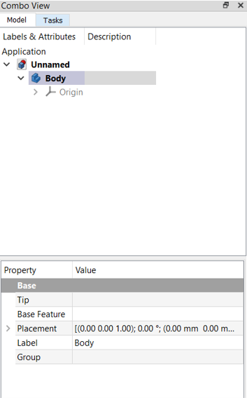
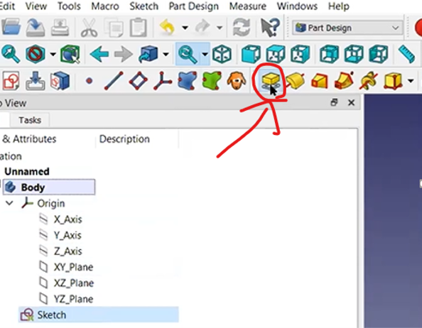
Create body Started
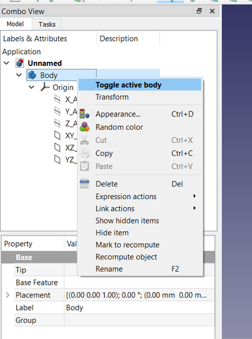
Lets start with creating a body, When you create a body you will see in the model , each body in free cad has origin , its set of basic object it usually 3 axix xyz and planes xy-xz-yz
Hit space to show it and its also on all other objects when you hit space it will hide it
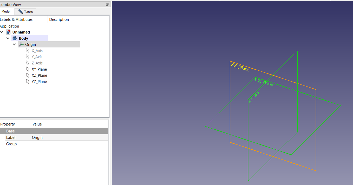
- its important to toggle the object to activate it
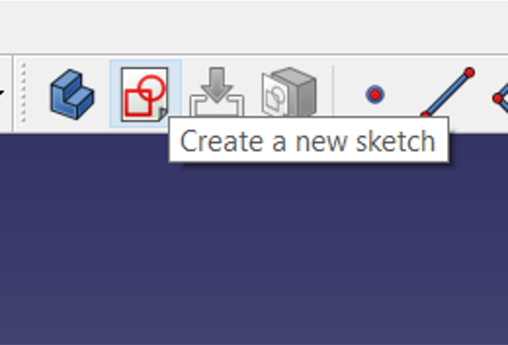
- Then first thing to do is to create sketch , it’s a way of modeling , its like from the beginning to design as engineer to start by drawing a sketch
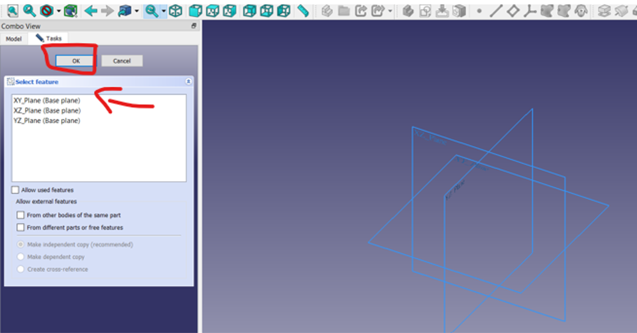
- Then you have to select the plane that you want to work on
- Once you start the plane, the view will change to top view to this plane, then you can draw objects with sketch tools.
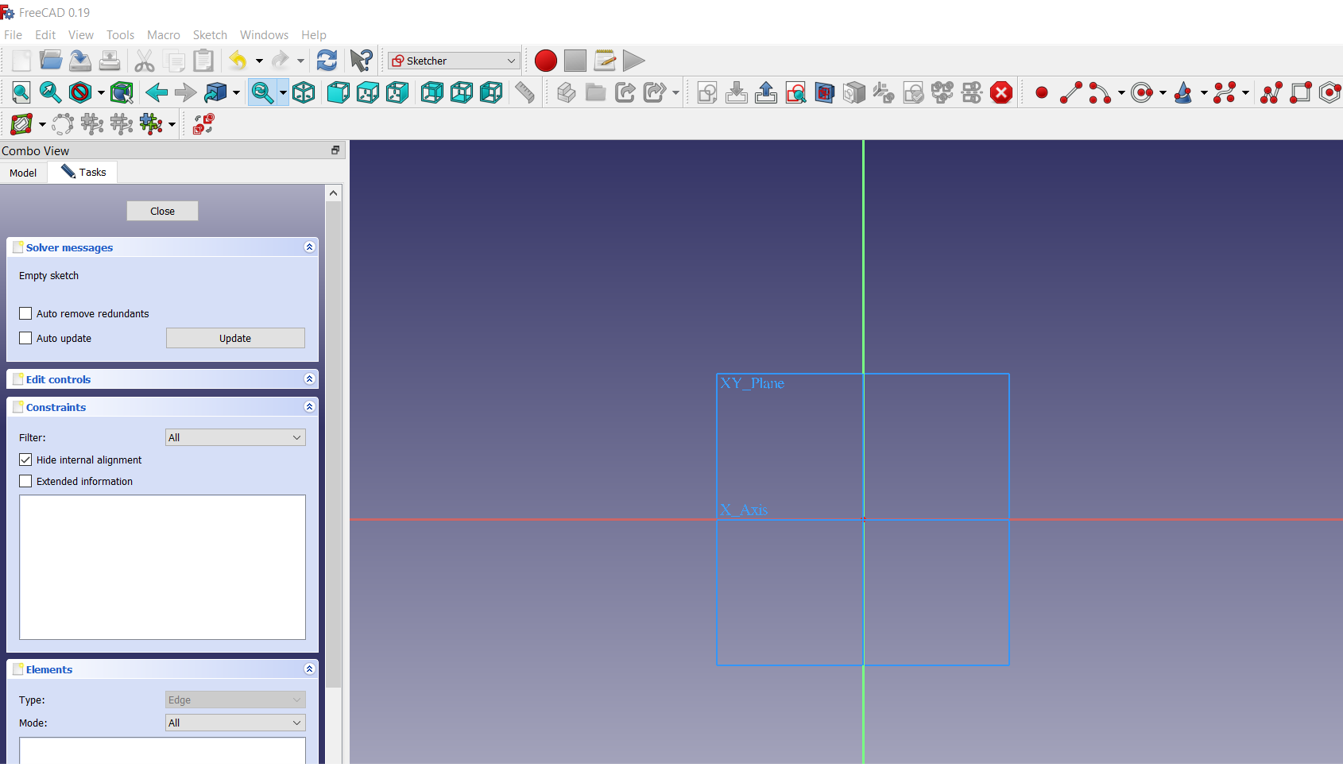
Sketch
- Test the sketches tools by draw some lines square ,circle , angle , etc
 sketch test
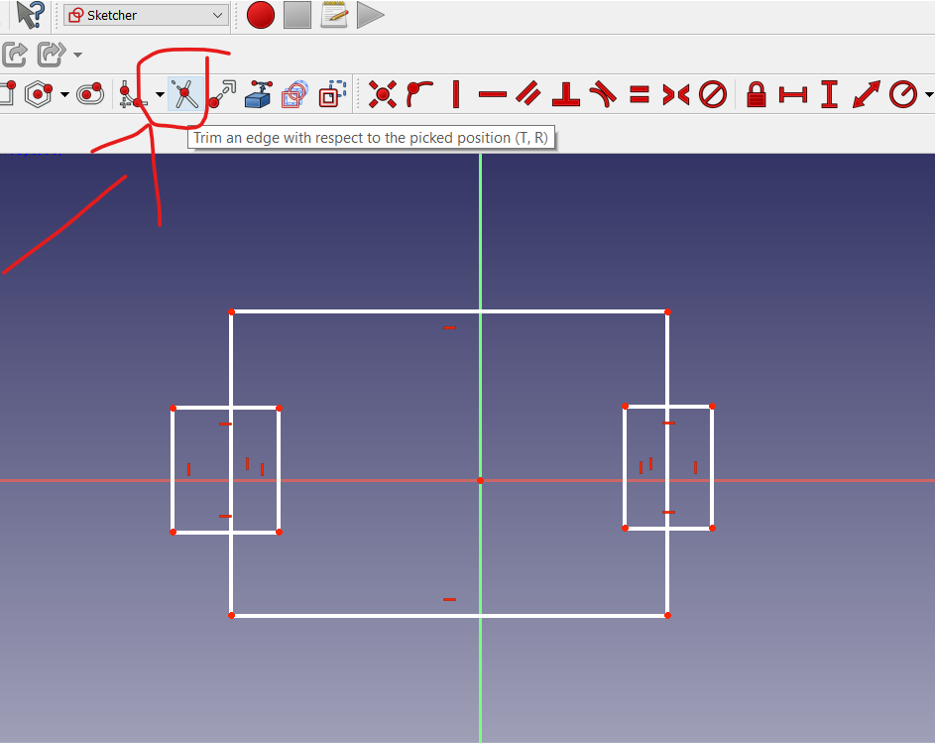
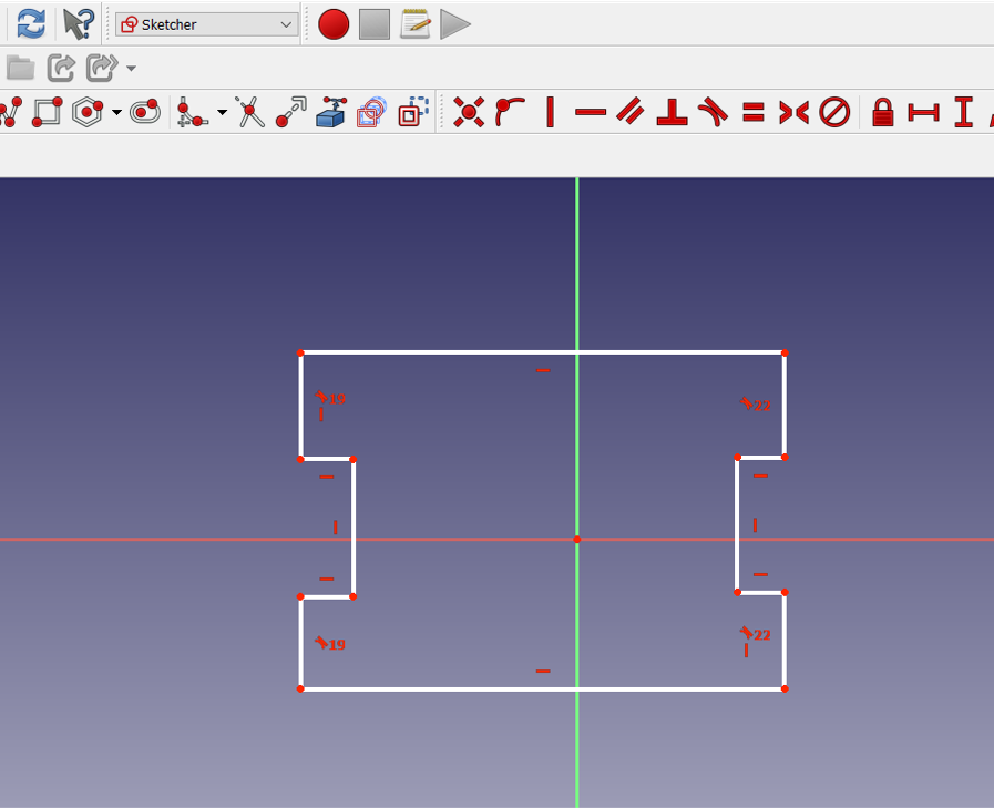
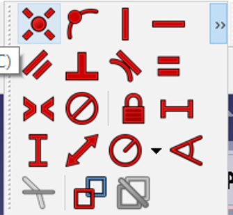
Trim
Trim means cut little part from the object. When two objects or lines are crossing each other and we want to delete any part of them then we can use the trim command to delete that part.
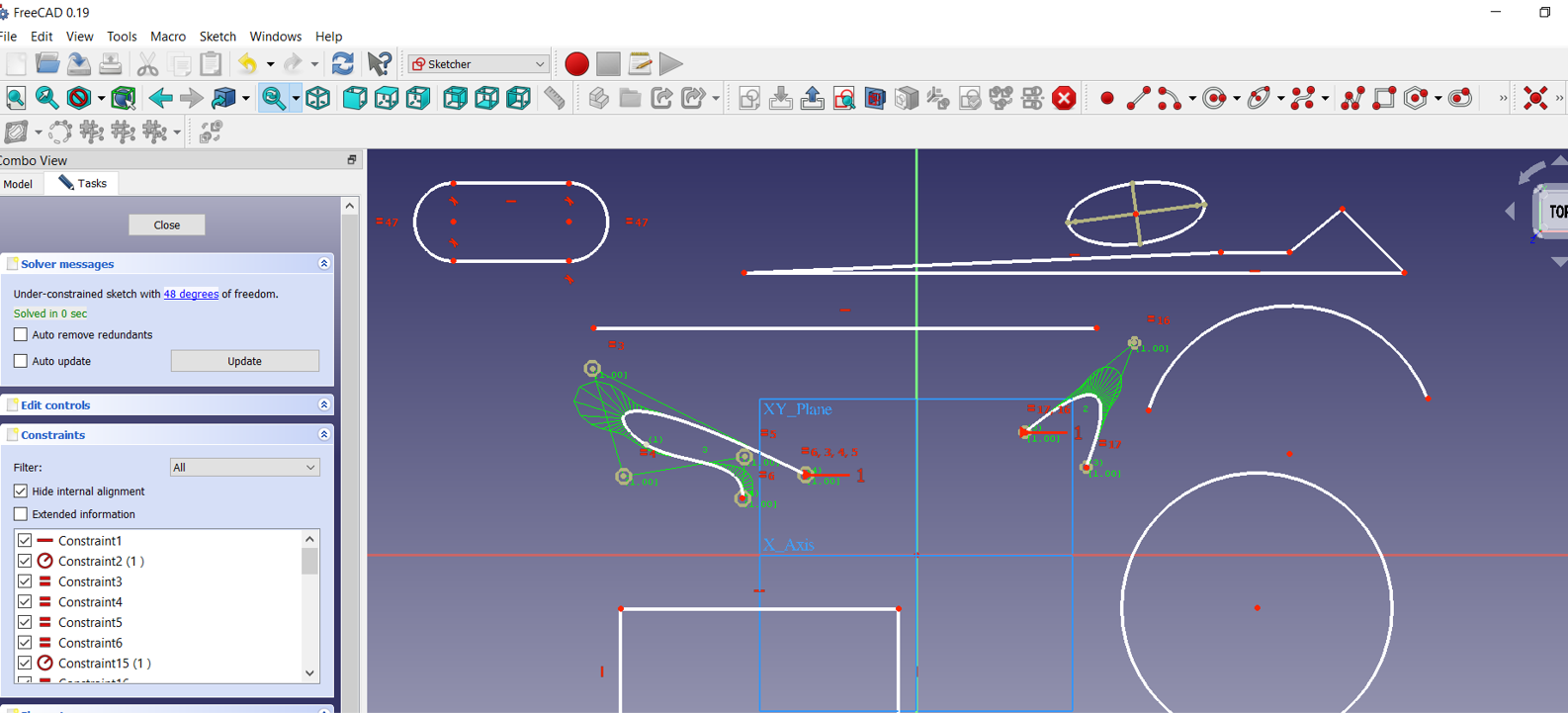
constraints?
In the design phase of a project, constraints provide a way to enforce requirements when experimenting with different designs or when making changes. Changes made to objects can adjust other objects automatically, and restrict changes to distance and angle values. With constraints, you can.
There are two types of constraints: geometric and dimensional.
- Geometric constraints are used to control the relationships of objects in respect to each other.
- Dimensional constraints are used to control the distance, angle, radius, and length values of objects.
Equality constraints
Equality constraints are constraints that always have to be enforced. That is, they are always “binding”.
Fix a Point onto object constraints
The order you select the line and point does not matter. The point will always move to line. In other words, the line remains fixed.
Vertical and horizontal constraints
Horizontal and vertical geometric constraints force two points, a line or a polyline segment to be parallel to the X-axis (horizontal) or the Y-axis (vertical) of the current coordinate system.
The vertical and Horizontal constrain can be applied in the lines only
Parallel constraints
The parallel constraint is used to make two lines of our sketch parallel. First, we click on the parallel constraint in the sketch palette then we click on the two lines that we wish to be parallel with each other on our sketch.
this use of geometry make you wonder that what you study in high school actually has benefit
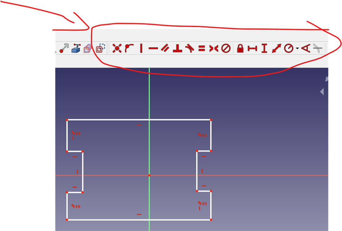
Dimensional constraints
constraints are used to control the distance, angle, radius, and length values of objects.
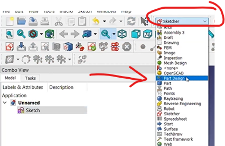
Transform sketch to 3D
To transform sketch to 3d you need first to Change the workbench from Sketcher to part design, and then select your sketch you want to extrude and then click pad a Selected sketch
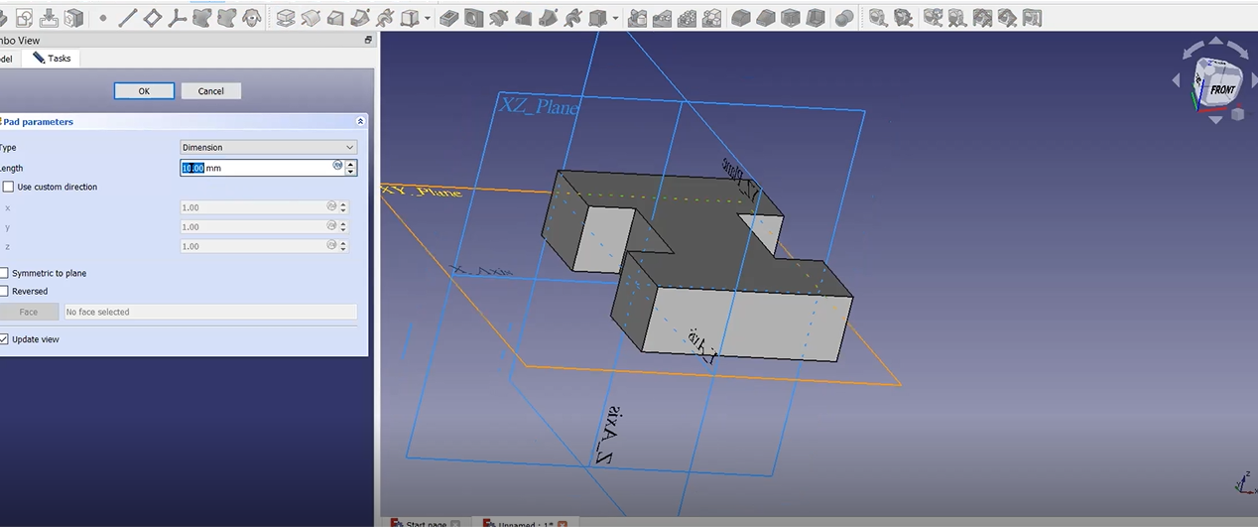
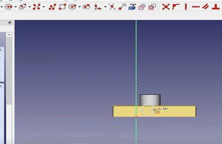
Pad
in other CAD software they call this function extrude, after click pad the selected sketch now you need to specify the type of dimension and length for the pad
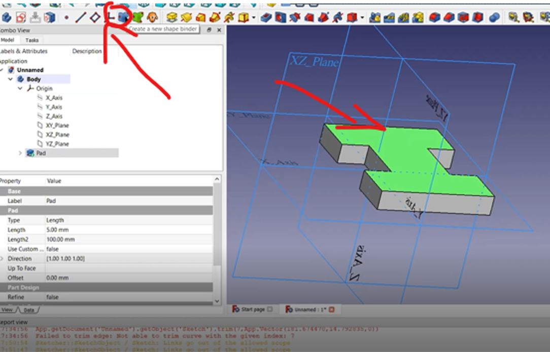
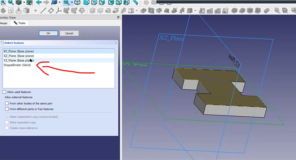
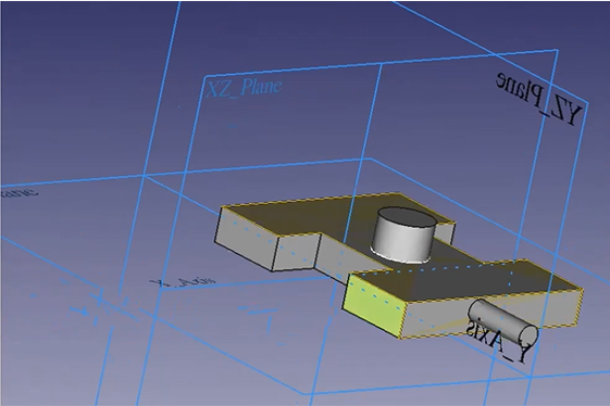
Drawing on top of a 3D shape ( Shape binder )
####### ShapeBinder is a proxy inside a body which serves as a placeholder for its source object. You can select everything for external references, which you can in its source body.
- To Draw on top of any face of 3d body you need first to create a shpe binder, that will enable you to create a sketch on top of that face
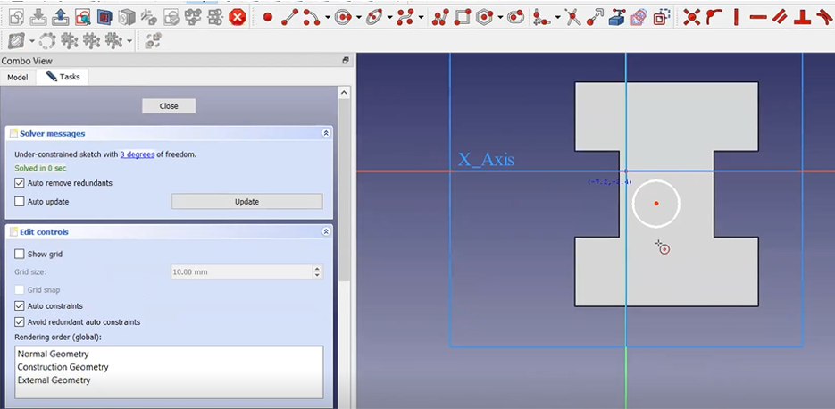
- then you can create a skech and start drawing
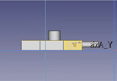
####### draw a circle on top a face
- after you created shape binder you can start a sketch and draw anything on top of it for example lets draw a circle
- then pad this circle
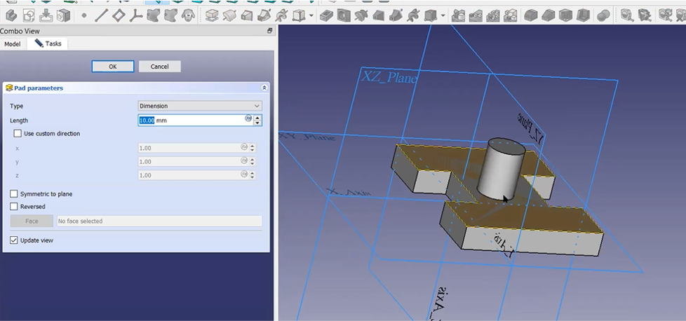
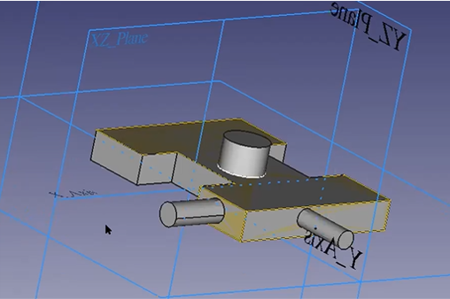
with the same function you can create on every face of an object
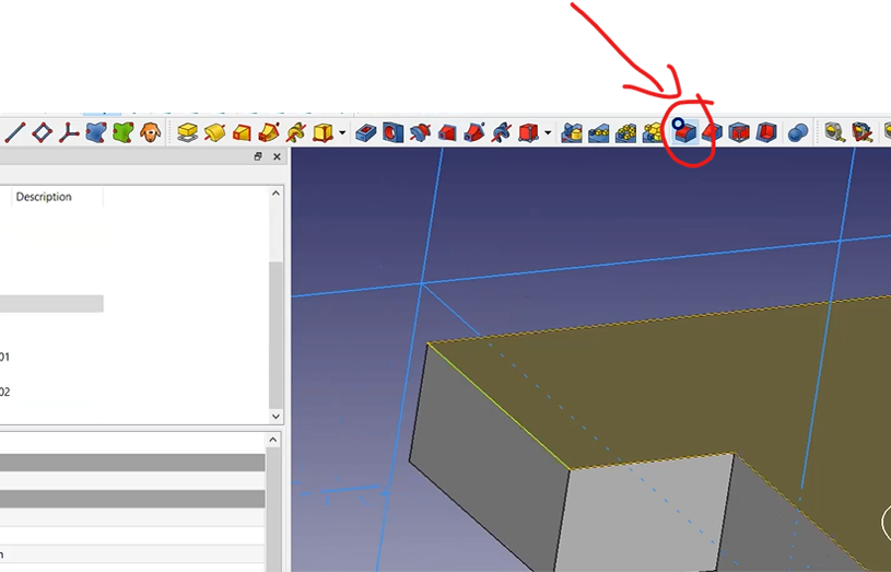
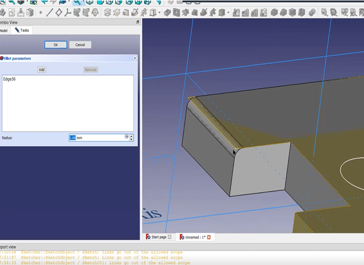
Fillet
Select an edge line first on a 3D Shape then click Fillet
OneShape

Onshape is a computer-aided design (CAD) software system, delivered over the Internet via a Software as a Service (SAAS) model. It makes extensive use of cloud computing, with compute-intensive processing and rendering performed on Internet-based servers, and users are able to interact with the system via a web browser or the iOS and Android apps.
Create account
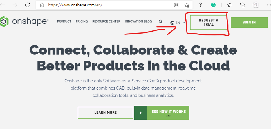
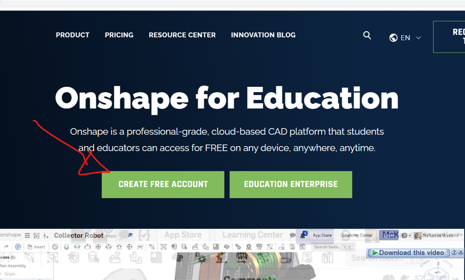
first thing to do is to go to the website and create account, what good about OnShape that it gives a free accounts for student, you can create free account by clicking request a trial, then Get the free student account
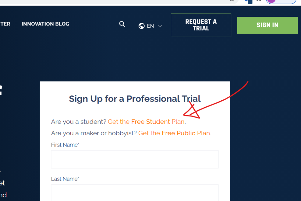
Create free account
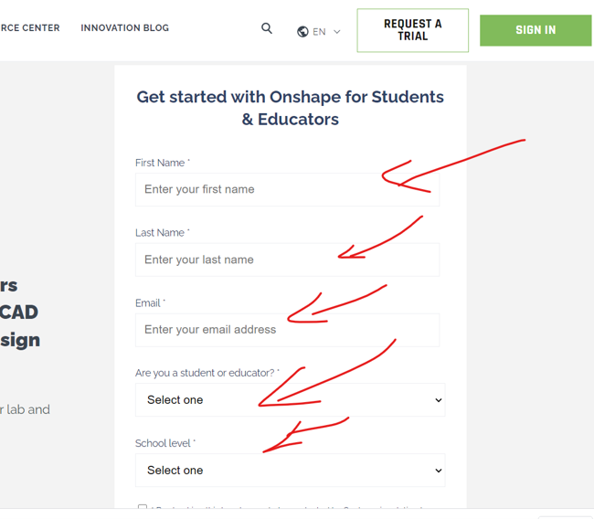
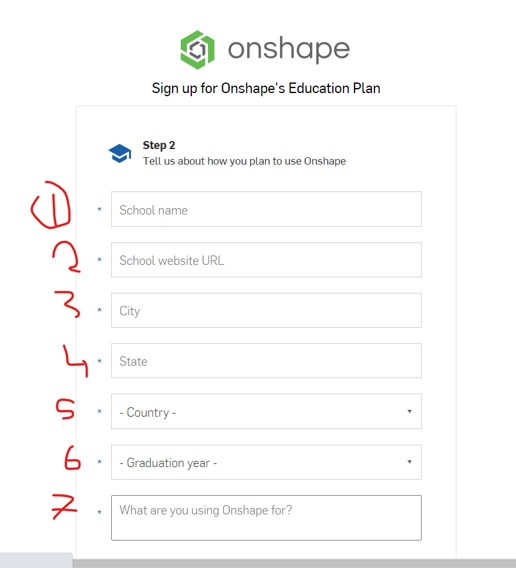
then click Free account and fill the information needed.
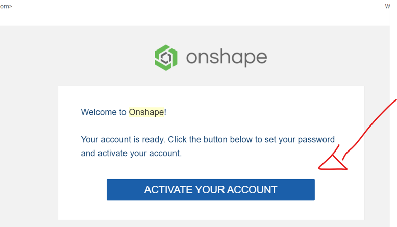
Activate account
once you submit the request an activation link will be sent to your email, you need to activate your account by clicking the activation link in your email
Getting Started Setting
Few more steps and your good to go, the first time you log in after activating your account, onshape will ask you to fix some setting.
- Set your default unit of measure, this unit is the one you are going to use as default in your designs.
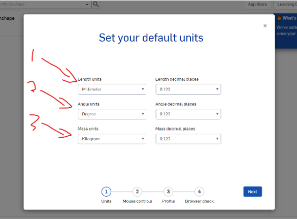
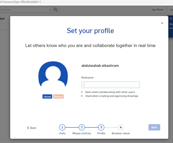
- set a profile image and name, onshape is a cloud base and you can create a profile in the cloud and share your designs with others and they can follow you too.
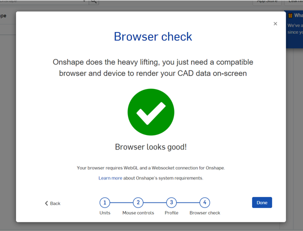
- last thing onshape will do is to check the browser that you are using
Create a project
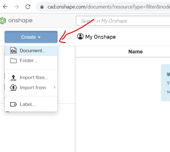
now everything is settled and your are ready to create a project.
-
from the main menu click create , then document
-
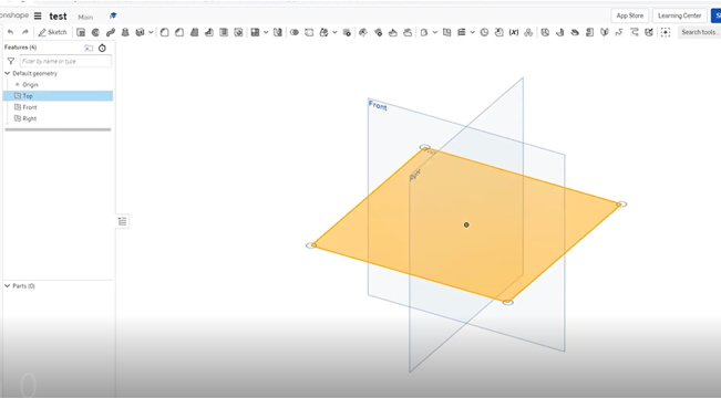
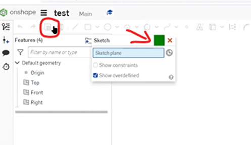
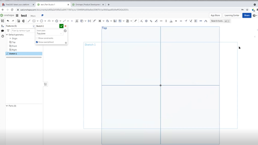
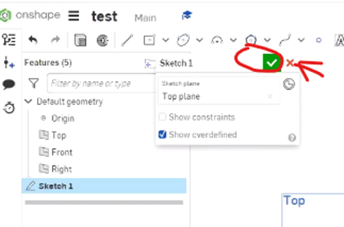
to start drawing you need to create a sketch first, start by choosing the face that you want to start with, then click create sketch
Single line VS Polyline
there is tow type of lines
- single line : you can drow it by holding the left button of the mouse,
- polyline : by click the left button of the mouse one click
Corner rectangle Vs Center Rectangle
for the corner you have tow option to choose from
- corner rectangle : this will draw a rectangle starting from the point you will click first and endup to the write top corner
- center rectangle : this option will draw a rectangle from the center point andexpand as you move the mouse curser away
Circles
therer is three type of circles
- center point : is the normal way cad will draw a cricle starting from the center and expand as you move the mouse away
- tow point circle : this option will draw a circle depending on tow points as you see in the video below
- ellipse : its type of circle that have the shape of eggs
Trim
to use trim function here you need to click to scissor icon and then apply it to you shape, as you see in the video below
constrains
because we already explained most of the constrain here using free cad software i will just go around them and use some of them, you can see the video below to see the examples
- equal constrain
- vertical and horizontal constrain
- fix point to line constrain
- parallel constrain
- Dimensional constrain
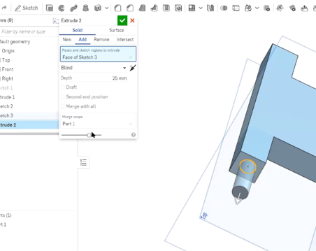
transfor sketch to 3D ( Extrude )
to transform the sketch to 3D shaoe do as follow
- first close the sketch window
- then select the sketch you want to extrude, and click the extrude i cone
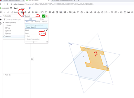
- you can specify the length of the extrude
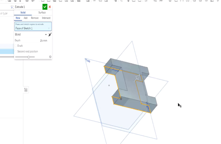
- Or just pull the arrow till you reach your desired length
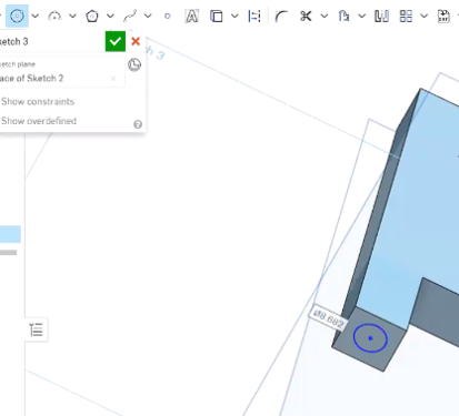
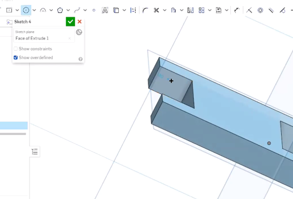
Draw on top of the body
to draw on top of other body or objects you need to
- select the face you want to draw on
- click create sketch
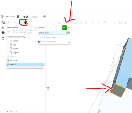
- then you can draw on that face
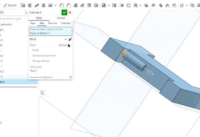
-
and you can even extrude it
-
by following this steps you can draw on any face of an object
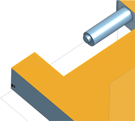
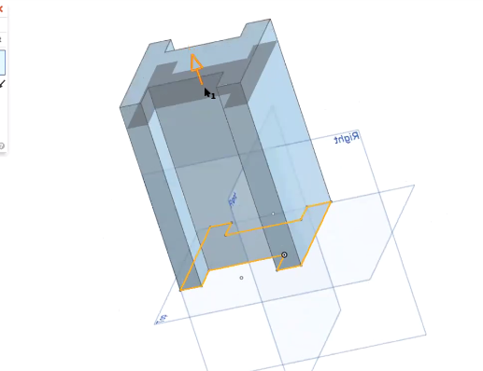
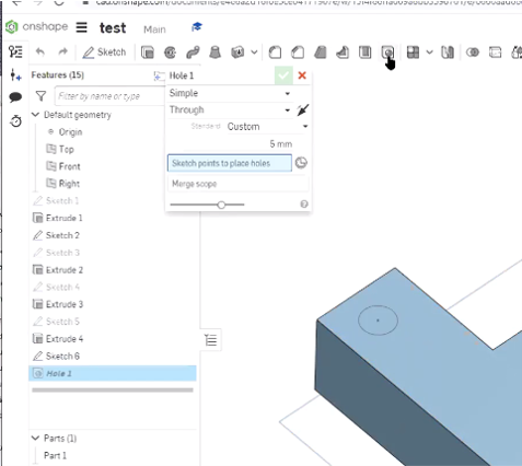
Make hall on body
to use the hall function is like extrude but it substract a sketch from a body instate of adding on it
-
start by select the face and create a sketch on it
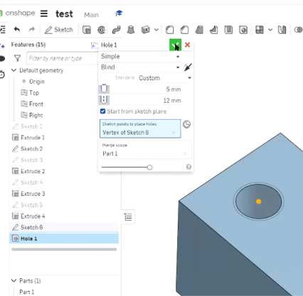
-
then draw a the shape of the hall

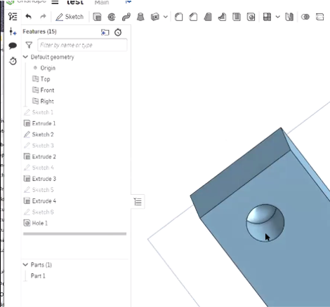
-
then click hall button from the top bar
Design a joint for the final project
- my final project structure is a Hexagon Shape, and in order to make the shape be easily assembled and de assembled i decided to design a 120' joint on each angle
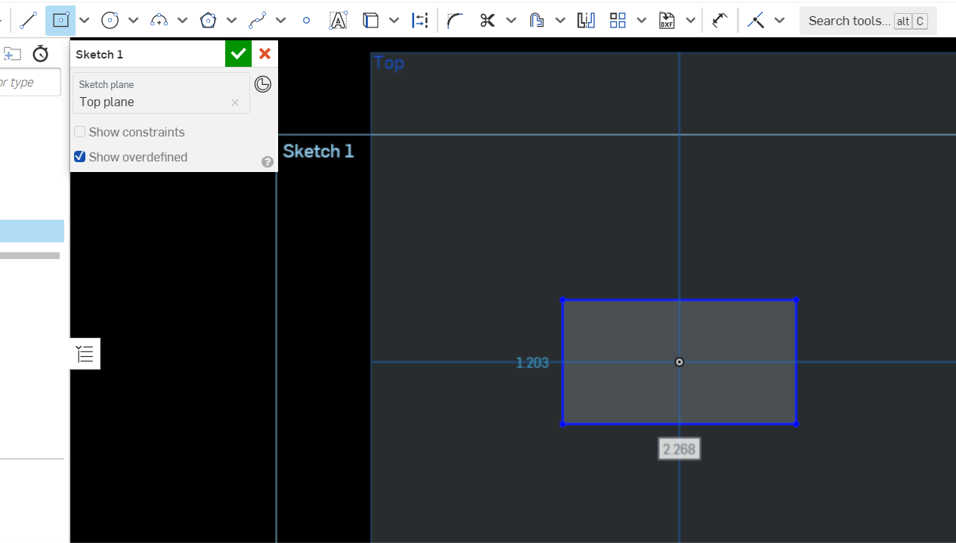
- First i have Created a sketch on the top view and used rectangle with center point, and i made the center point of the origin as my centered point for the rectangle.
-
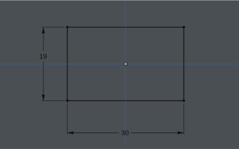
the i Used the dimensional constrain to adjust the dimention according to my design
-
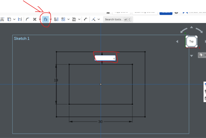
then i added an offset with 4 mm length around the rectangle
-
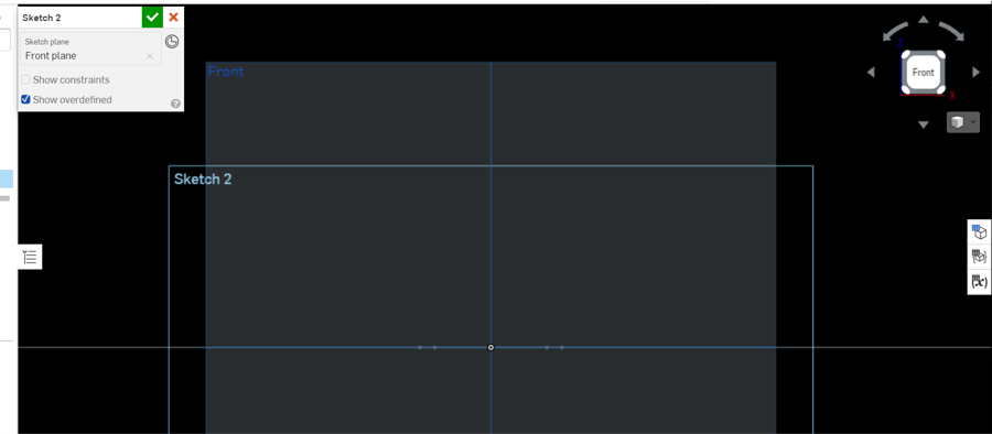
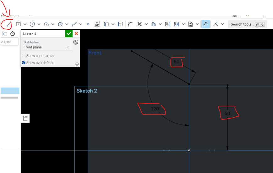
Then created a sketch on the front view
-
Then created a line and adjusted it with dimensional constrain , the angle will be 120 as it will to make a hexagon shape
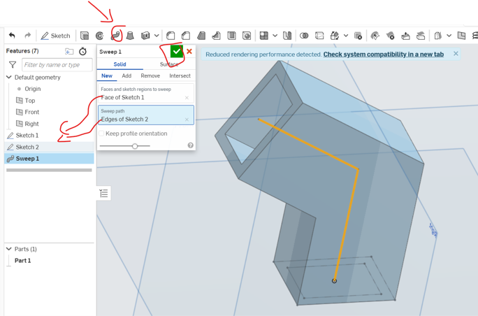
- Then I used sweep function, I choose sketch 1 as my face and sketch 2 as the path