
WEEK 10
Input devices
Group assignment: probe an input device's analog levels and digital signals.
Individual assignment: measure something: add a sensor to a microcontroller board that you have designed and read it
1. Group assignment
Go to the Sedicupct website
2. Individual Assignment
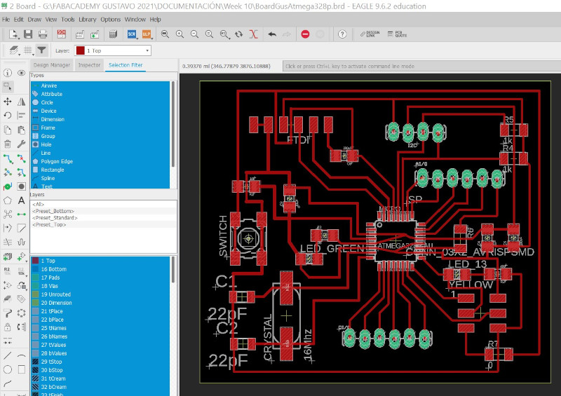
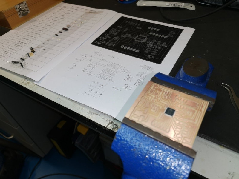
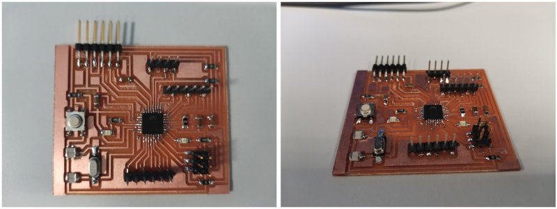
2.1 ATMega328p board design
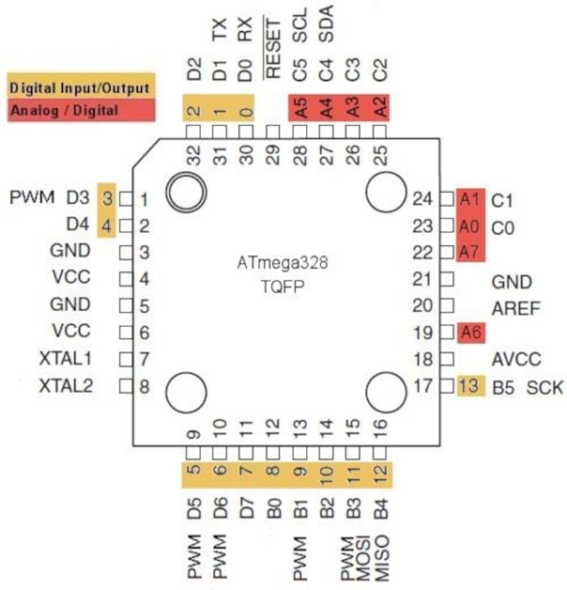
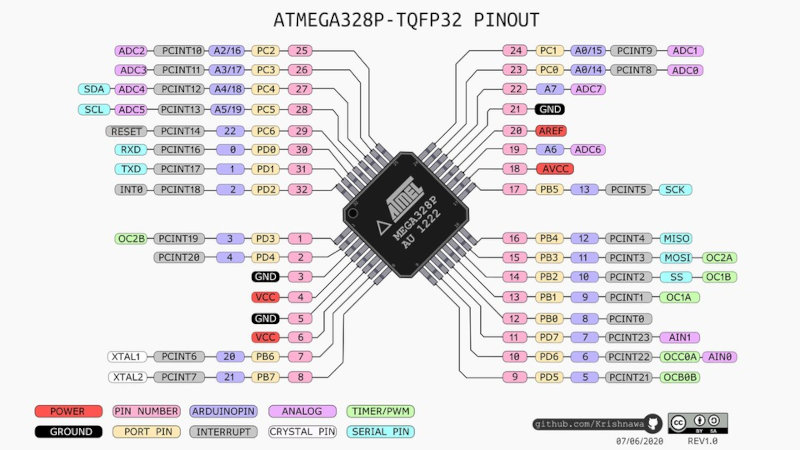
I have used the Atmega328p to configure all its pins. Classifying the I2C, FTDI, ISP ports and the pins of 6 digital I / O and 6 analog I / O. Use two sensors (gyroscope / accelerometer and a GPS). The datashhet of the Atmega328p.
I have followed the tutorial of Satshakit. and Lola Ojados (Final Project) that used the ATMega328p microcontroller.
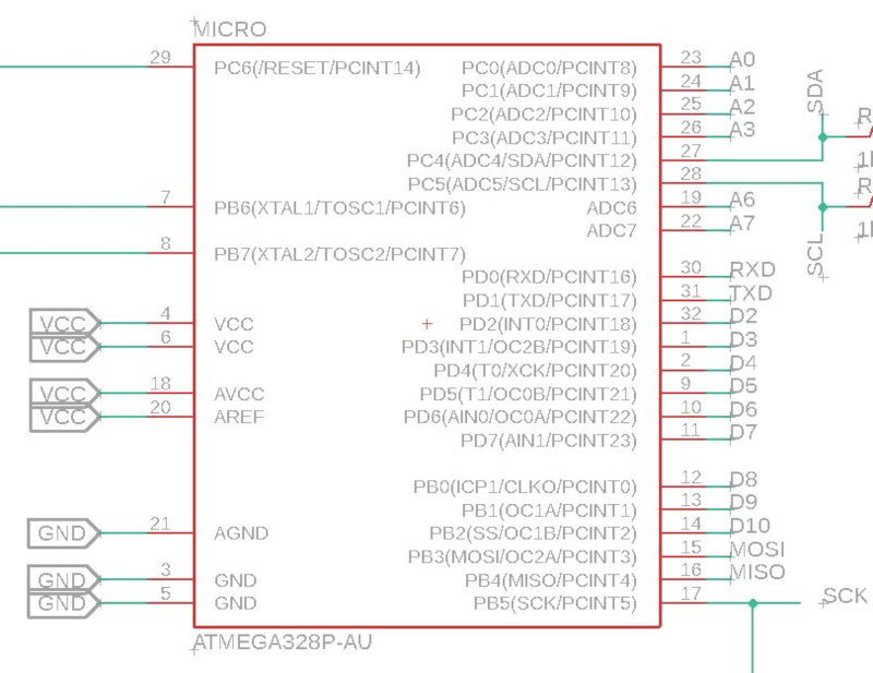
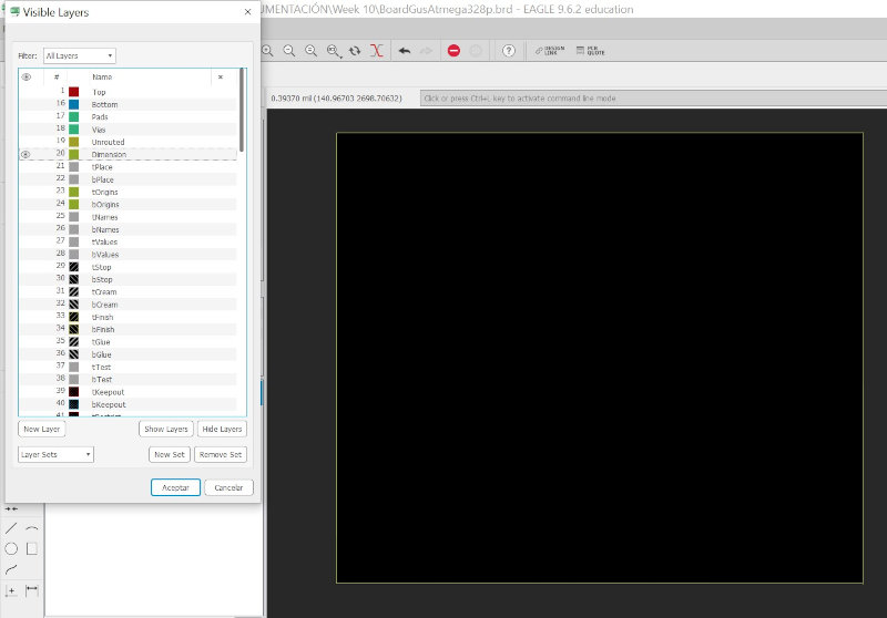
Configure the pins of the Atmega328p microcontroller in the Eagle Schematic.
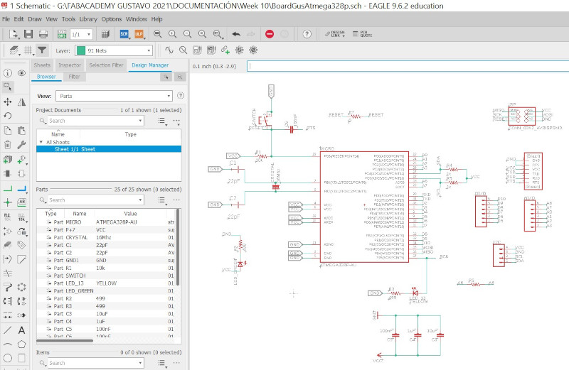
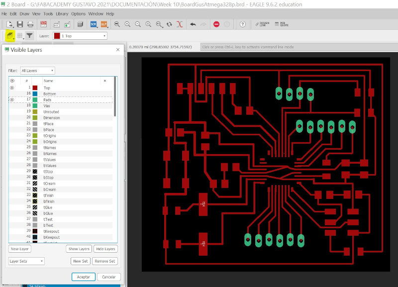
Select layers (Top / Pads).
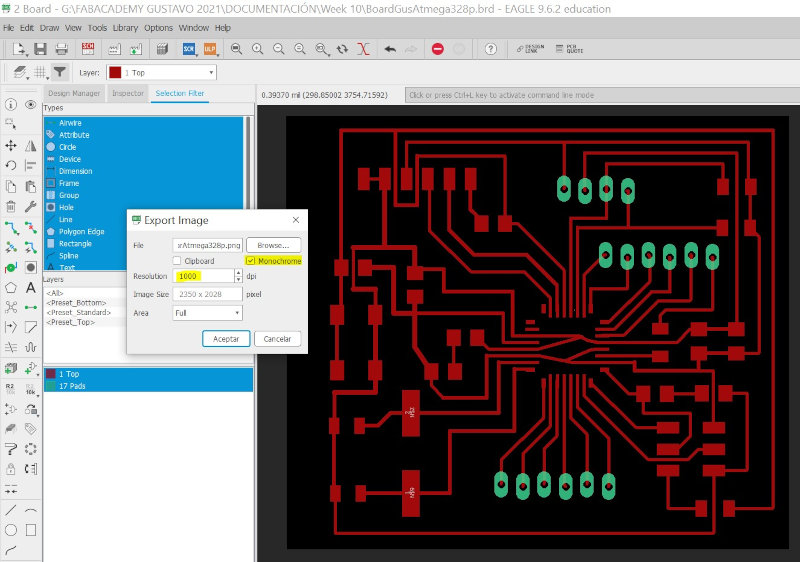
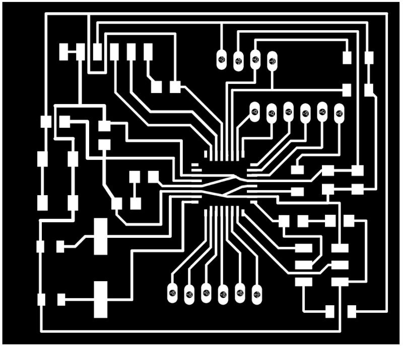
Export Image (Monochrome / Resolution:1000pdi / format:.png).
Generate the outline (layer: Dimension).
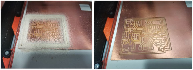
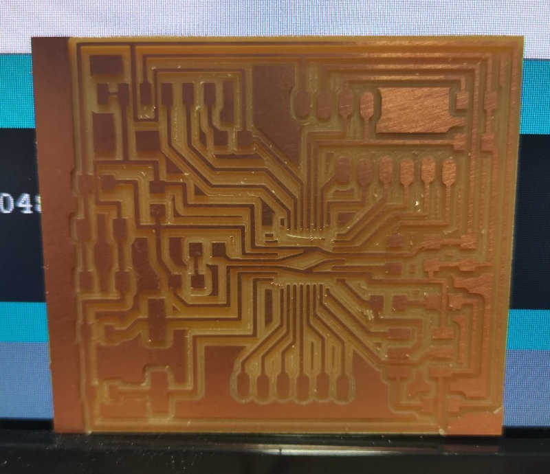
2.2 Board Milling
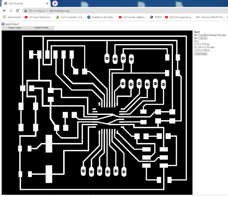
I use fabmodules.org to generate the milling file.
- input format = image (.png).
- output format = Rolland thousand (.rml).
- Process = PCB traces (1/64) for the interior.
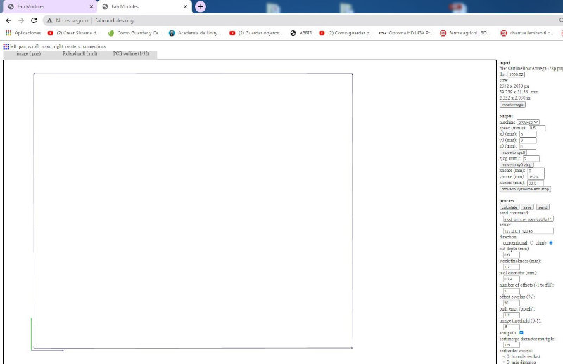
I set the milling parameters for the SRM-20 Milling Machine

For the outline cut I carry out the same procedure, only I modify the following parameters: Process=PCB traces(1/32) for outline and reduce speed mm/s)=0.5.
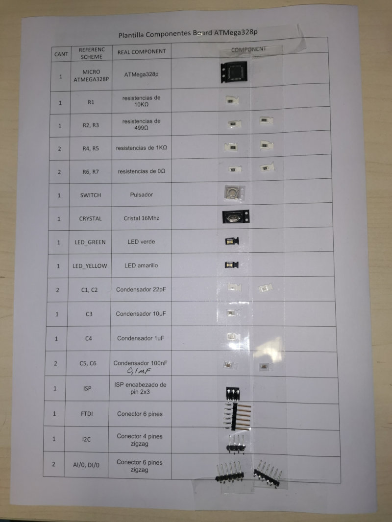
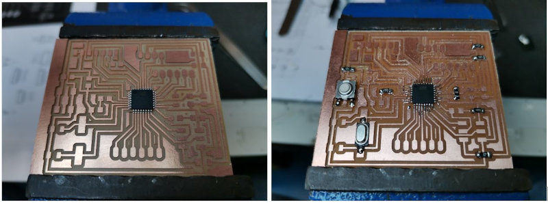
2.3 Solder electronic board
Use a template to classify electronic components.
3 MPU 6050 SENSOR
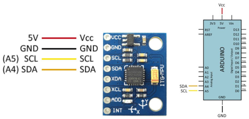
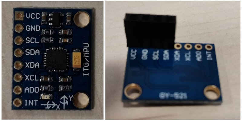
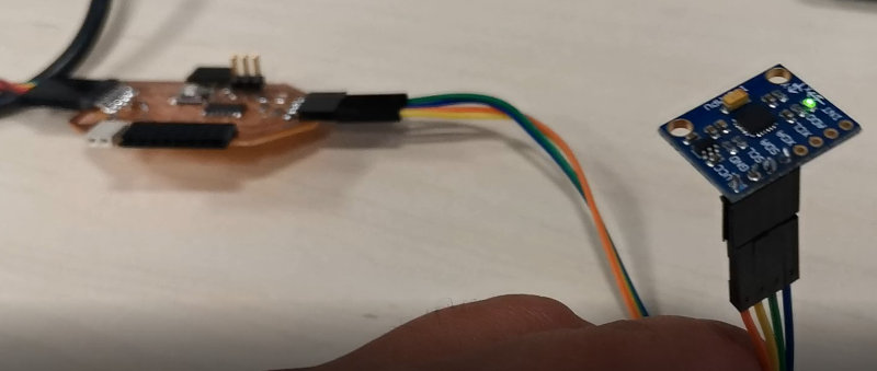
The MPU-6050 is a six degrees of freedom (6DOF) Inertial Measurement Unit (IMU) manufactured by Invensense, combining a 3-axis accelerometer and a 3-axis gyroscope. Communication can be done both by SPI and by I2C bus. They are integrated into modules such as the GY-521 that incorporate the electronics necessary to connect it easily to an Arduino. On most modules, this includes a voltage regulator that allows direct 5V power supply.
3 Assembly scheme
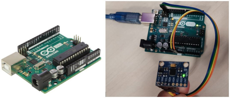
Power the module from Arduino through GND and 5V and connect the SDA and SCL pin of Arduino with the corresponding pins of the sensor. The connection on the Arduino is as follows.
I have followed two tutorials
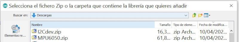
To read the MPU-6050 we will use the library developed by Jeff Rowberg available at this link. .
We will also use the I2Cdev library developed by the same author, which improves I2C communication. Open Arduino IDE and add the libraries I2Cdev and MPU6050.zip.
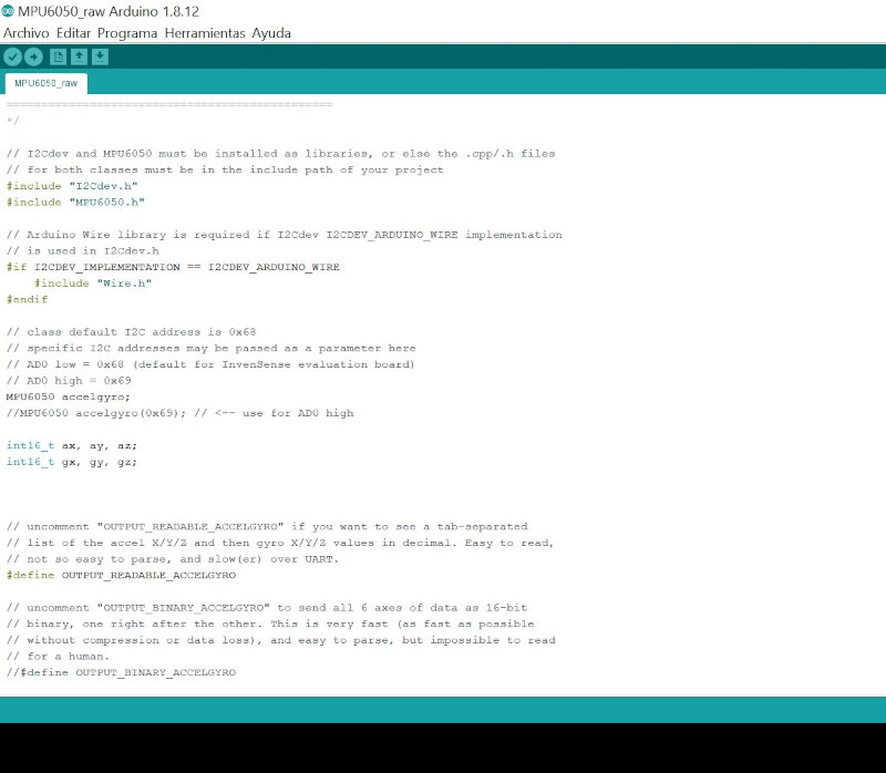
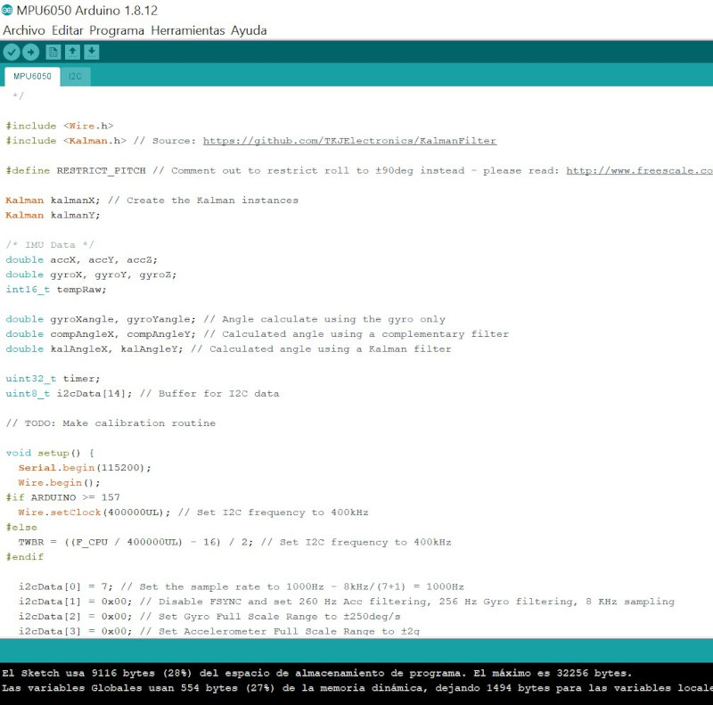
Open the example in “File / examples / MPU6025 / MPU6025_raw.
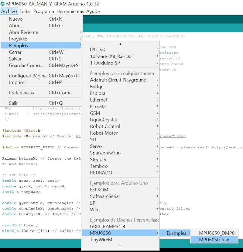
This program is very simple, and what it does is read and print the raw values that the accelerometers and gyroscopes send to the arduino, that is, without processing at all. Build the simple.
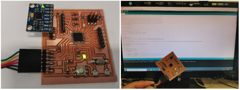
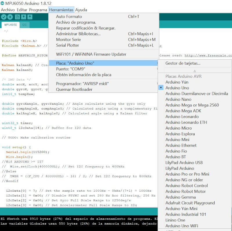
I'm going to do initial tests with the arduino UNO that uses the same Atmega328p microcontroller. I connect the MPU6020 sensor board to the arduino Uno.
Open the serial port (38400 baudios).
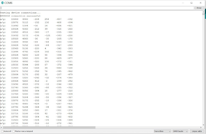
The serial console is at 38400 baud, to ensure that the IMUs receive sufficient speed because otherwise the information will be lost on the serial port.
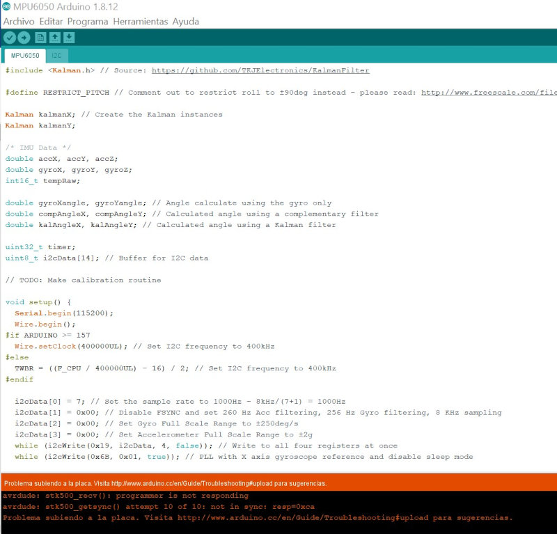
I have tried another library that includes a kalman filter to remove noise from signals. Download the file and add the library in arduino ide. Open (Examples / Kalman Filter Library / MPU6050).
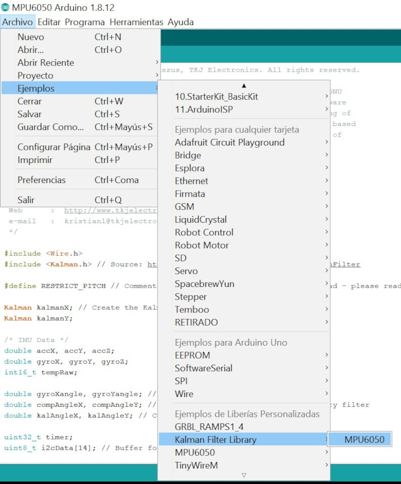
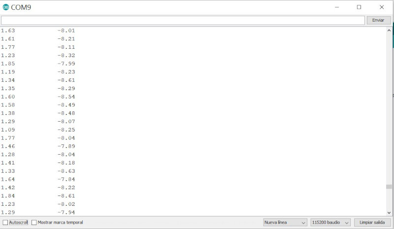
Open the serial port. The sensor data will appear in the first 4 columns and the values with the kalman filter in the right columns.
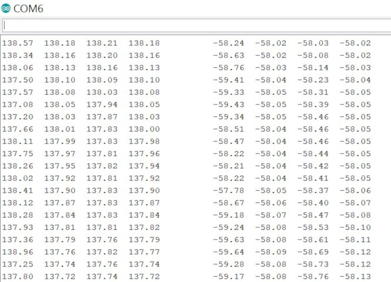
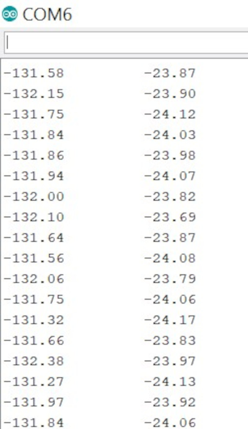
I have commented on the print lines in the serial port and I have only left the pitch and roll enabled.
4 GPS SENSOR (IES-SHIELD-GPS)
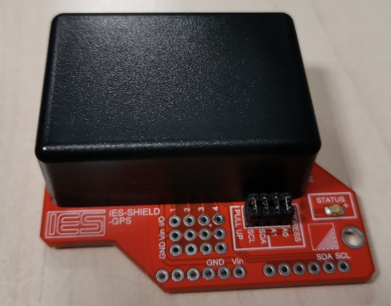
The IES-SHIELD-GPS is a highly integrated Global Positioning System allowing your robotic application to determine its location on the earth’s surface. Specifically targeted at the Arduino Duemilanove / UNO board user, [MEGA and NANO boards also supported] the GPM.S features I2 C communication to leave the serial [TX/RX] port free for other functions eg. wireless communication. GPS data received by the IES-SHIELD-GPS is stored within internal registers which are updated once per second and include:
- Latitude (i.e. vertical).
- Longitude (i.e. horizontal) .
- Altitude (metres).
- Time & date (UTC).
- Heading (True & Magnetic).
- Speed (kilometres per hour).
- Satellites detected.
In addition, the IES-SHIELD-GPS features an on-board fully configurable four line programmable IO and analogue input port with automatic measurement.
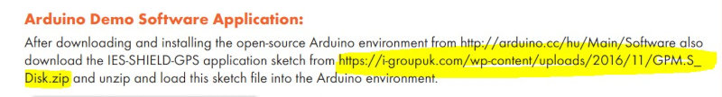
Sensor web , Datasheet and IES-SHIELD-GPS Quick Start Guide
Download the library .
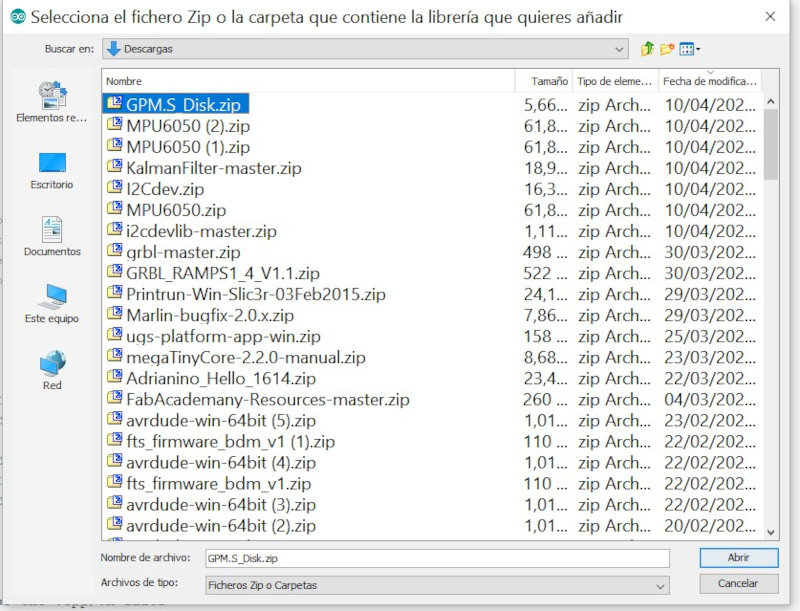
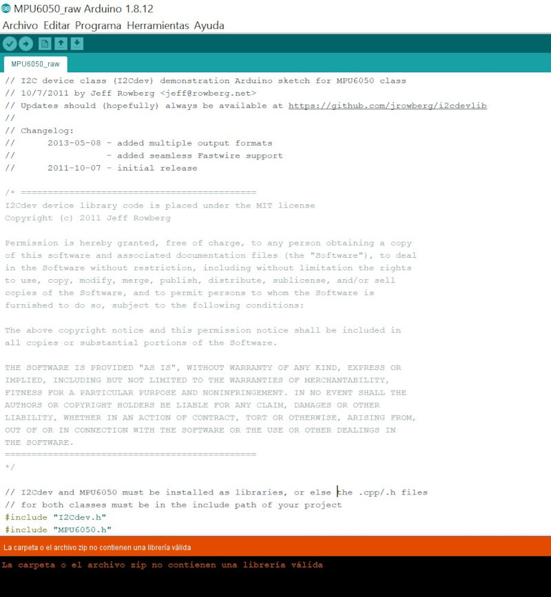
This manufacturer's library when compiled in arduino sends an error.
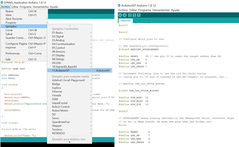
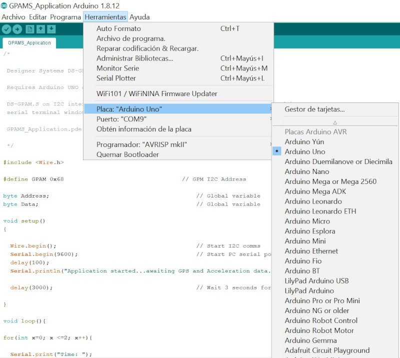
I have used an example "GPAM_Application" to read the GPS data.
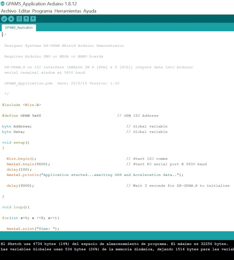
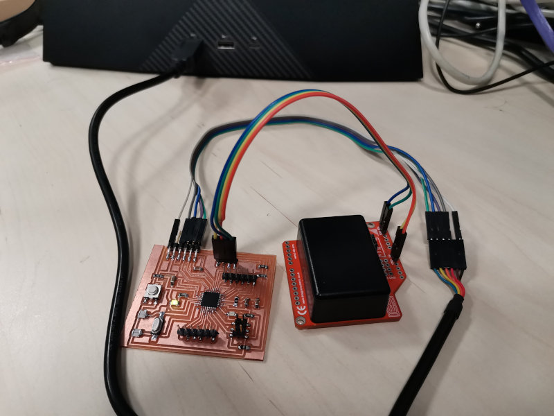
Connection: The IES-SHIELD-GPS should be connected to the Arduino or Raspberry-Pi boards using the supplied wires or plugged into the Arduino board after soldering pin headers into the IES-SHIELD-GPS board [not supplied]. The wiring diagram below shows the connections that need to be made:
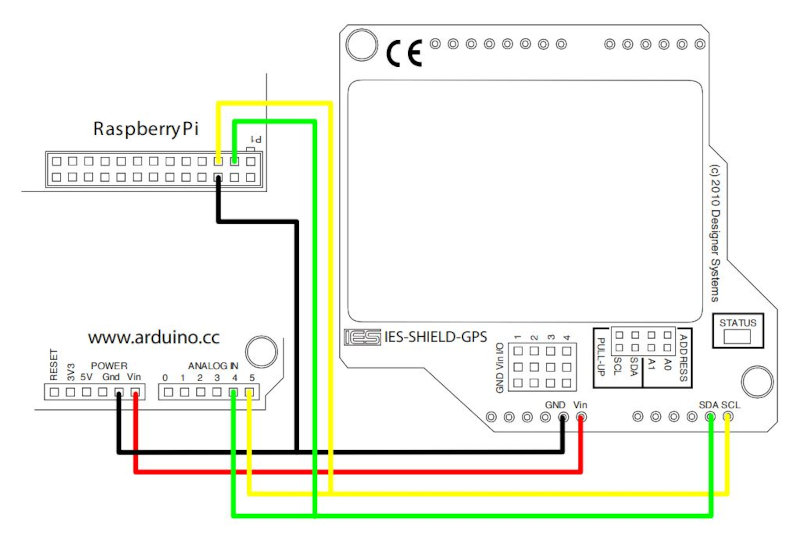
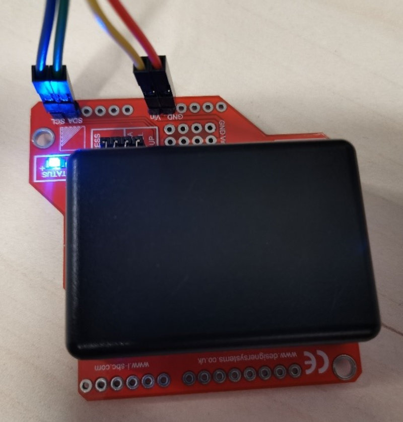
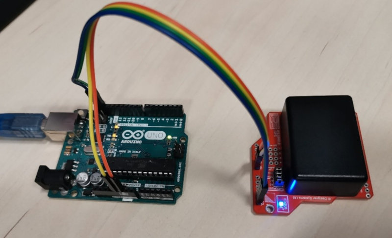
For the initial tests I have also used the Ardunio Uno. I use I2C to make the connection of the Gps and the arduino (Vin, Gnd, SDA and SCL).
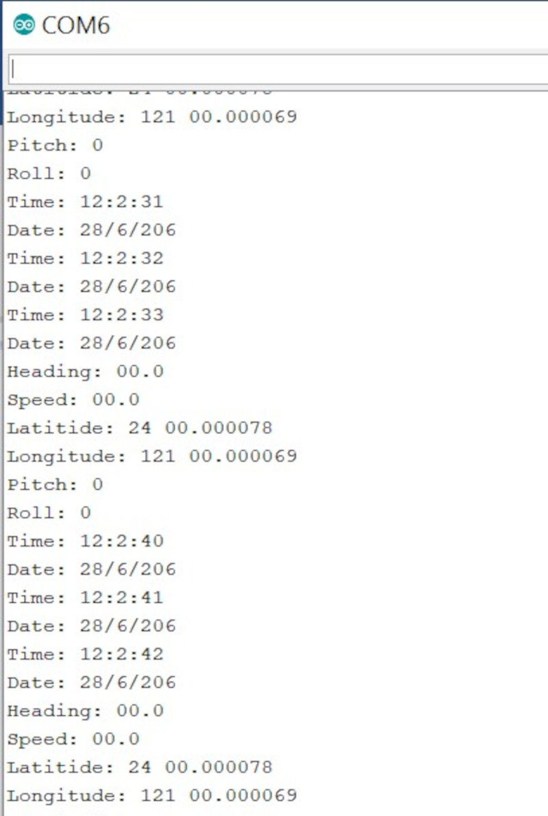
Open the serial port. I connect the SDA: 4 and SCL: 5. In the serial port it does not update the Time and remains without advancing.
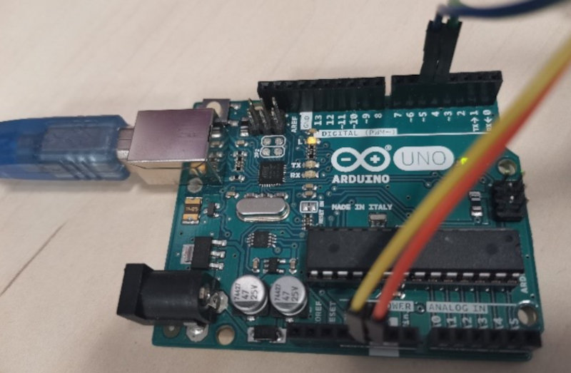
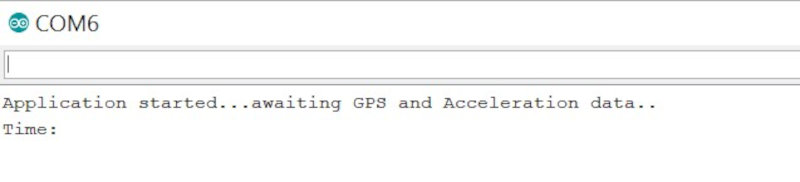
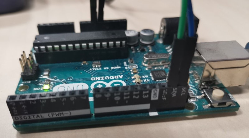
I connect the SDA: SDA of the arduino and SCL: SCL of the arduino and if it works.
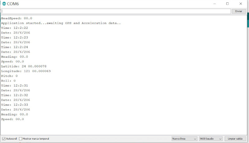
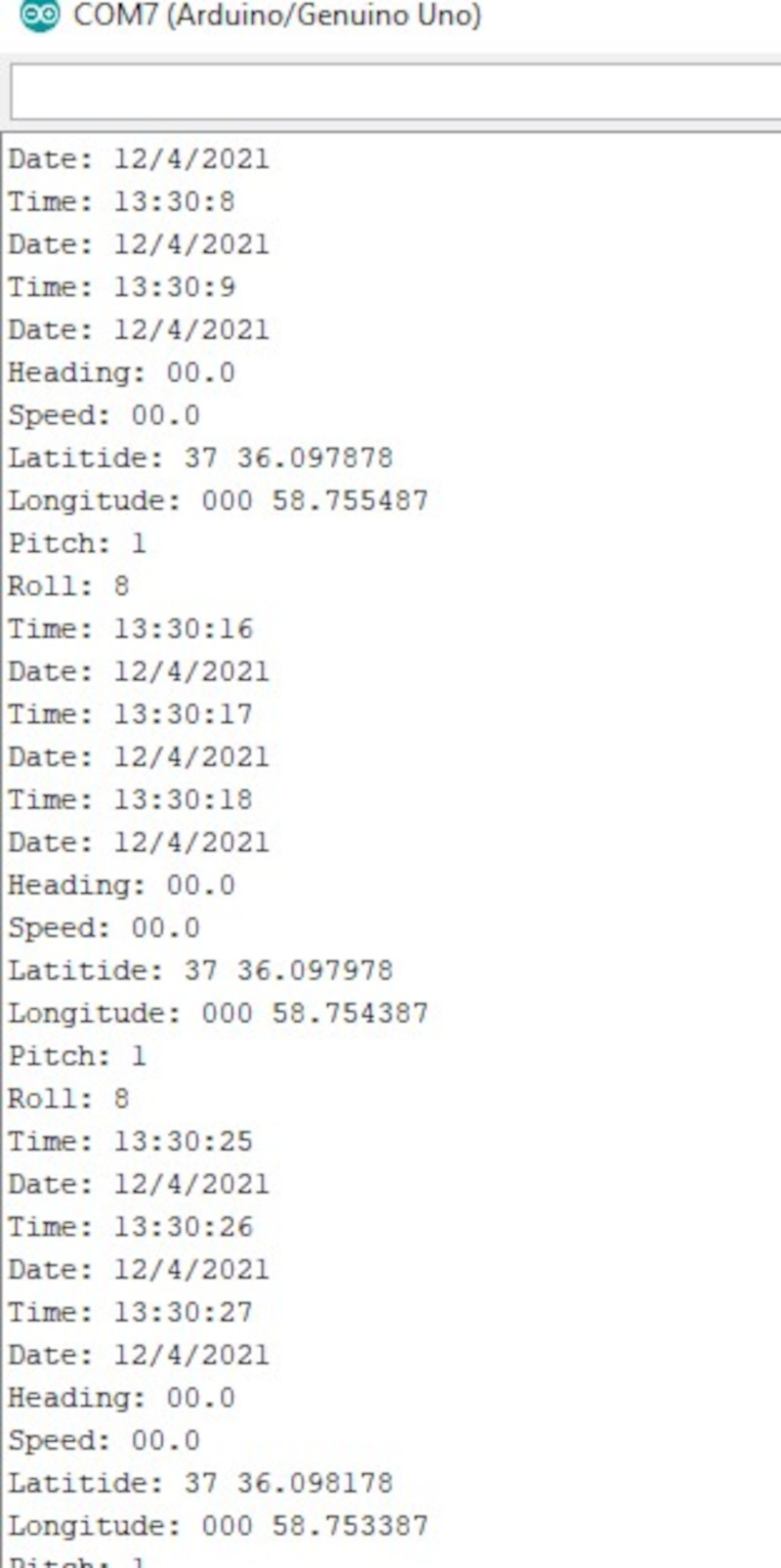
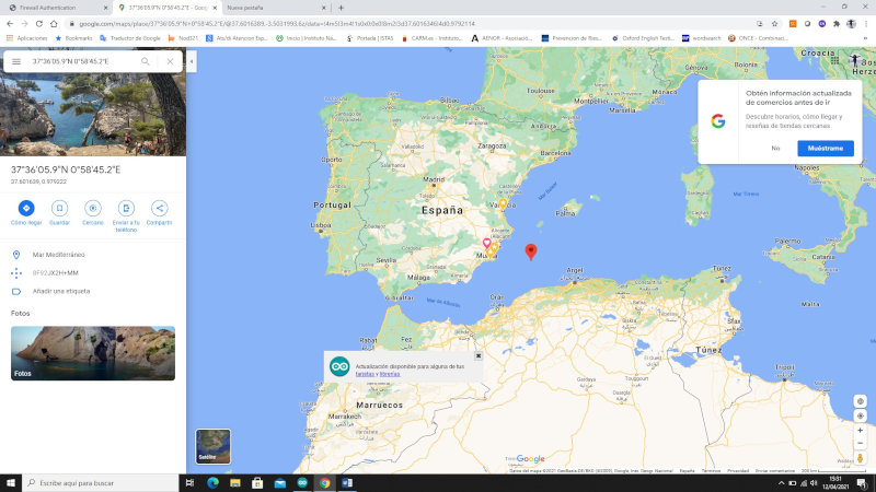
Testing with the GPS should be done outdoors to find the GPS signal. You have to wait several minutes for the Gps shield to update the date, time, altitude and longitude data.
5 Testing the sensors with the ATMega328p board
5.1 Testing the sensors MPU6050
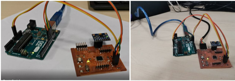
First perform a test with the MPU6050 sensor by connecting the ATMega328p board to the computer via the FTDI connector.
Load the program directly with the FTDI but the programmer is not responding.
Then make the connection through ISP with the arduino Uno. Use the ArduinoISP example to program my ATMega328p.
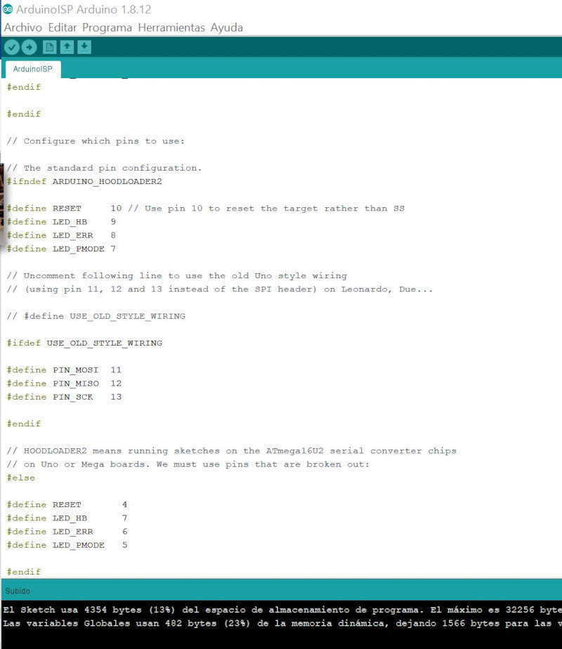
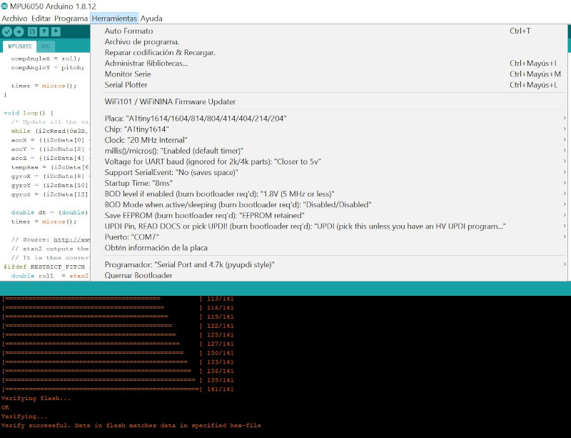
I open the MPU605 program on arduino and compile.
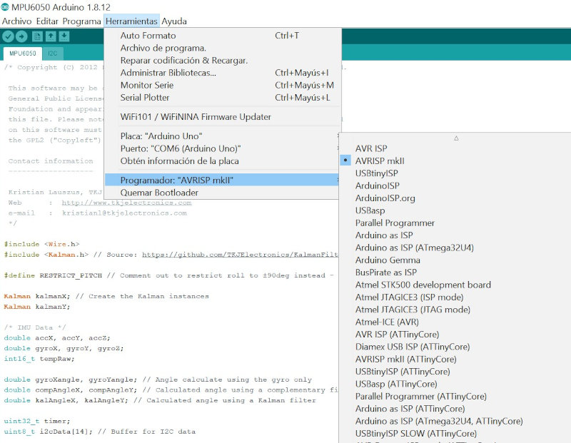
Compile successfully, I open the serial port but there is a write failure with the I2C port.
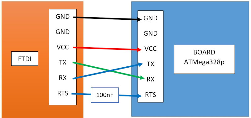
My colleague Alvaro Macian found the communication failure using the FTDI connector, you have to connect the RX of the FTDI to the TX of the board and the TX of the FTDI to the RX of the board, so if you compile the program correctly with the configuration of the arduino Uno make the changes to the RX and TX wiring between the FTDI connector and the board. I also connect the MPU6050 sensor to the board through the I2C port.
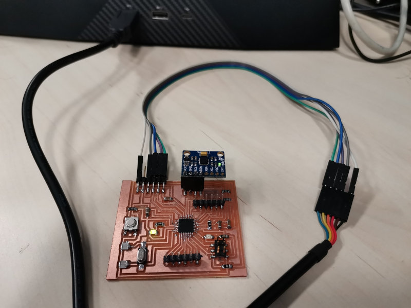
I open the serial port and the data of the pitch and roll of the MPU6050 sensor is correctly seen.
5.2 Testing the sensors GPS
I do the same procedure to load the GPS program and compile the program. I connect the GPS shield to the board through the I2C port.
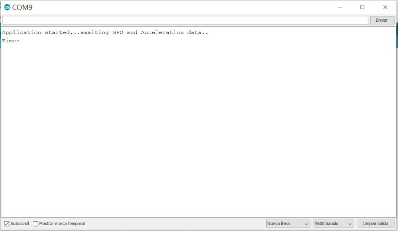
The program data is displayed correctly on the serial port, the GPS data is not updated because the tests are done inside a building. I do other outdoor tests to see the GPS data update.
In the regional review, Nuria advised me to use the fabusb to program my board.
Adrian Torres recommended that I program with the Adrianino that I did in week 8 Embedded programming 2.4 PROGRAMMING ADRIANINO (ATTINY1614) WITH ARDUINO.
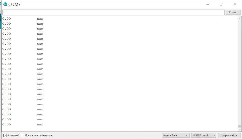
When I open the serial port I verify that the program has loaded correctly, but the sensor values are not correct.
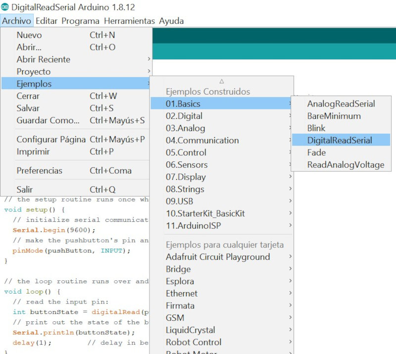
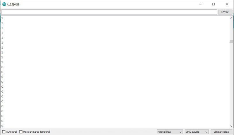
5.2 Testing the sensors EndStop Digital
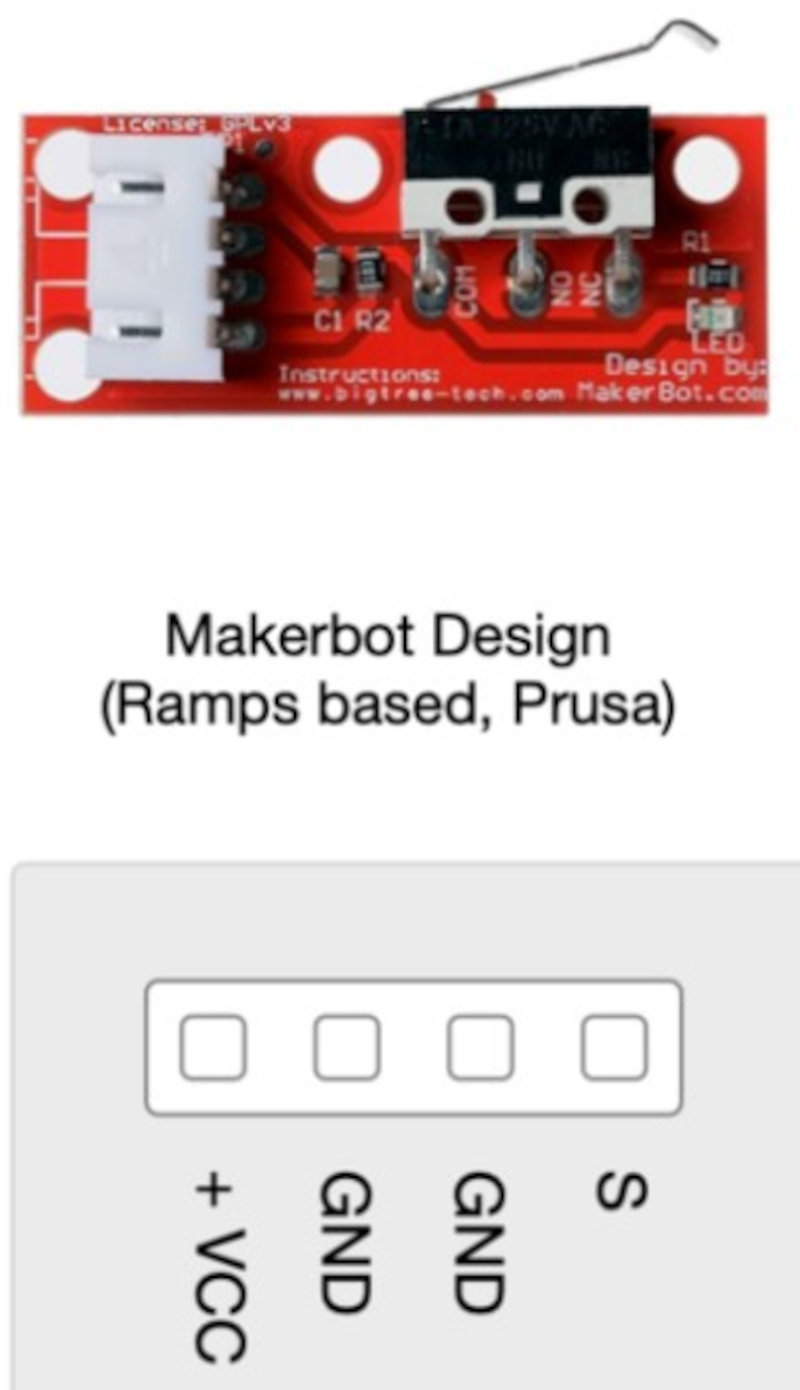
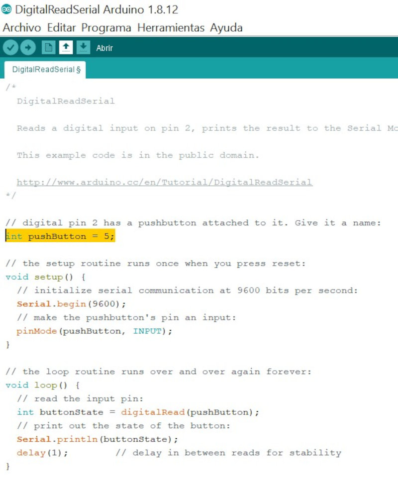
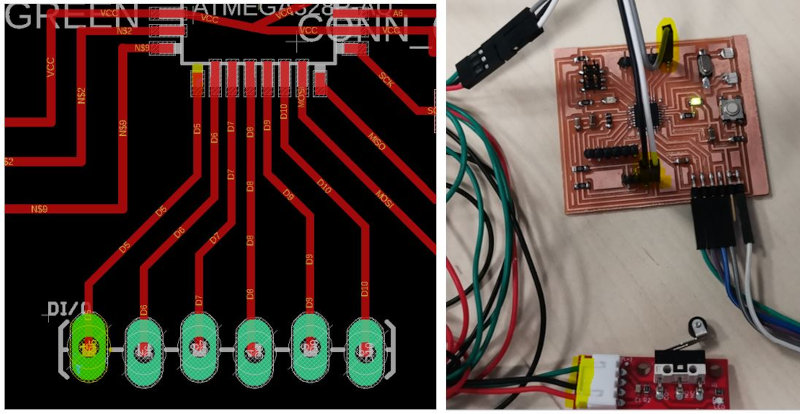
I use the arduino example (Examples / Basic / DigitalReadSerial). I modify the (int pushButton = 5) because I am going to use the Digital I / O 5 of the ATMega328p.
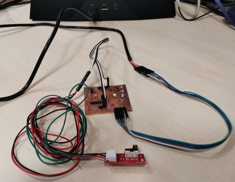
I connect the endstop signal to Digital 5 of the ATMega328p, Vcc and Gnd.
4. Conclusions of the week
How was the week?
This week I liked it a lot, I have designed and built my own arduino uno board, well actually I wanted to have an electronic board that takes advantage of all the pins of the ATmega328 microcontroller. Use the MPU6050 sensor that I am going to include in my final project.
What went wrong ?
- The library that appears on the IES-SHIELD-GPS website does not work and when compiling your example in arduino it gives an error so I used a library that I had used in a geolocation project a few years ago with the same GPS, this one did work. Testing with the GPS should be done outdoors to find the GPS signal. You have to wait several minutes for the Gps shield to update the date, time, altitude and longitude data.
- When I compiled the arduino program of the MPU sensors it did not work with my boar ATmega328, it was a communication failure using the FTDI connector, to solve it you have to connect the RX of the FTDI to the TX of the board and the TX of the FTDI to the RX of the board , so if you compile the program correctly with the Arduino Uno configuration it makes the changes to the RX and TX wiring between the FTDI connector and the board.
What went well?
The MPU6050 and GPS sensor tests work fine with the arduino Uno. With the digital EndStop sensor connected to my ATmega328 boar it worked flawlessly..
3. My files
project in eagle of my board ATmega328