VR SCOOTER
PROJECT DEVELOPMENT
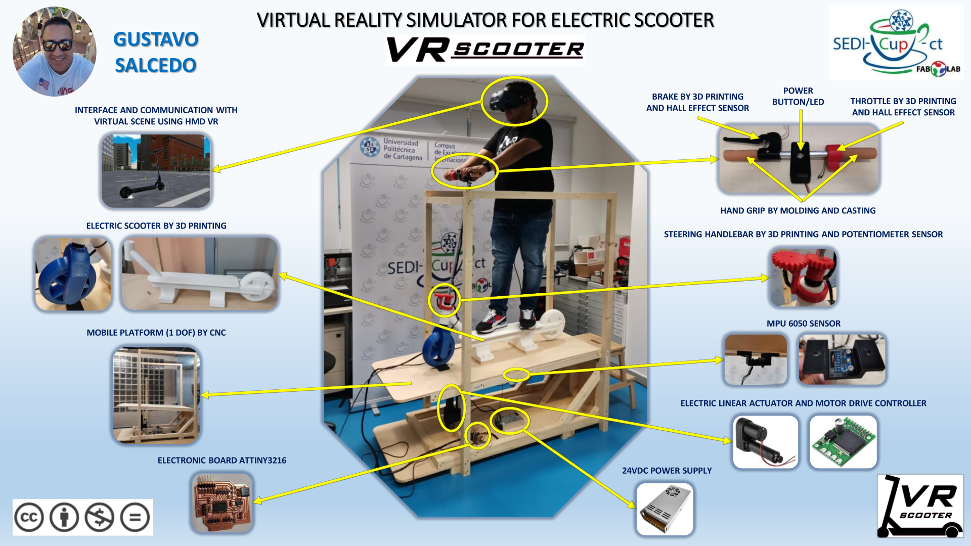
MY IDEA FOR THE FINAL PROJECT IS TO BUILD A VIRTUAL REALITY SIMULATOR FOR ELECTRIC SCOOTER. "VR SCOOTER".
I design and build an electric scooter on a simulation platform that will integrate the movements made by the user in a virtual scenario created in Unity software, and it can also be viewed using Vive Cosmos HMD. This project is composed in 3 parts:
- Desing and construction of an electric scooter (not funcional). Replicate the structure and inputs.
- Design and development of a 1 degree of freedom platform.
- Creation scenario VR in Unity software and communicate with platform.
The user’s brake, throttle and steering handlebar actions are transferred to the virtual scene and their road slope are replicated on the platform.
1. PLATFORM
Design + mil + assemble (movement platform)
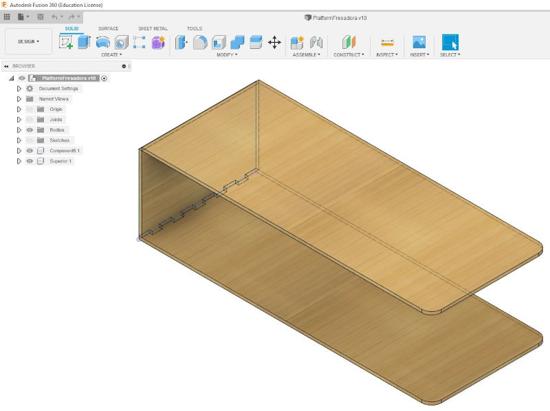
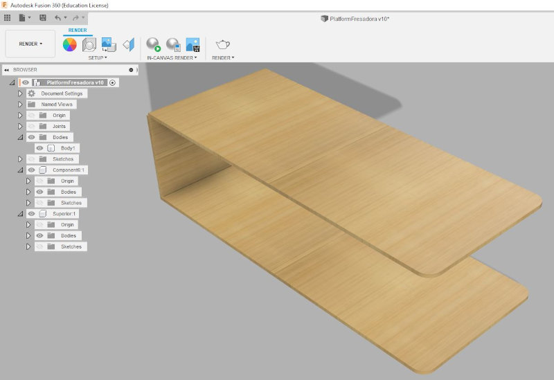
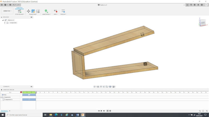
I have designed a wooden motion platform to generate pitch motion. Design in fusion360 the three parts (bottom, side and top).
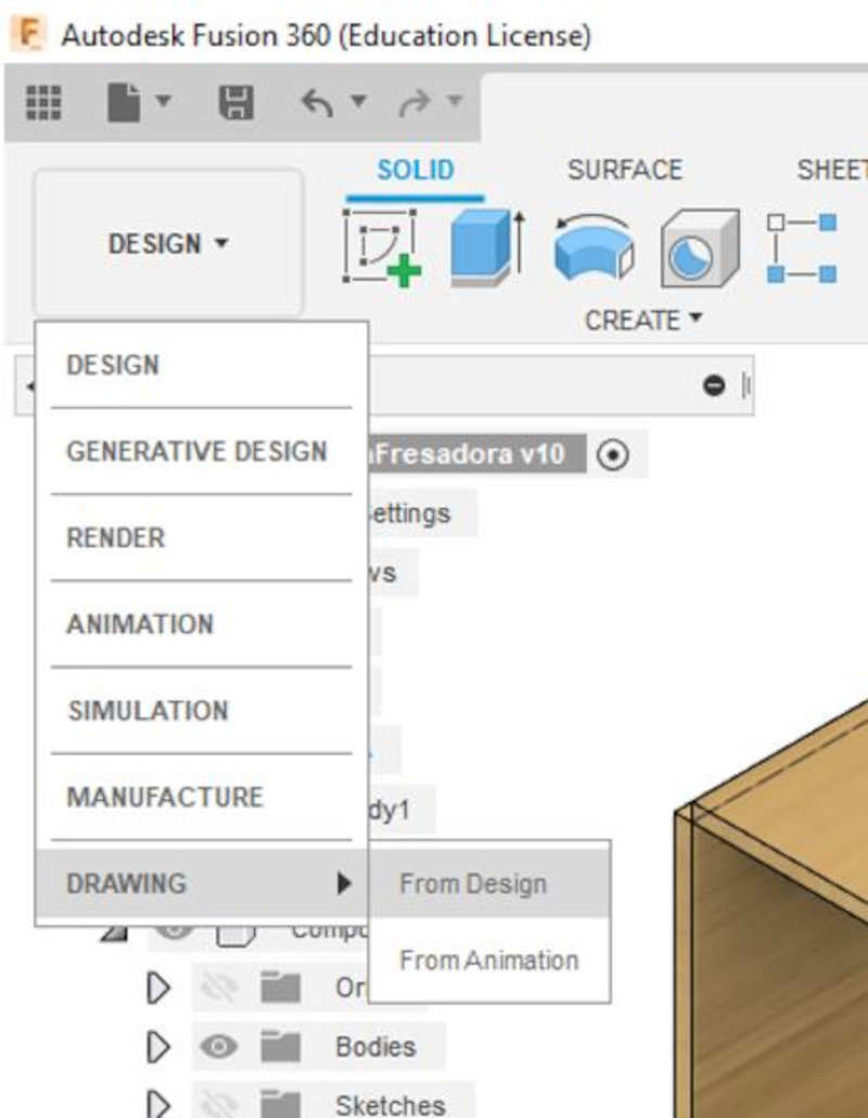
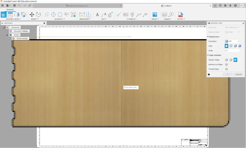
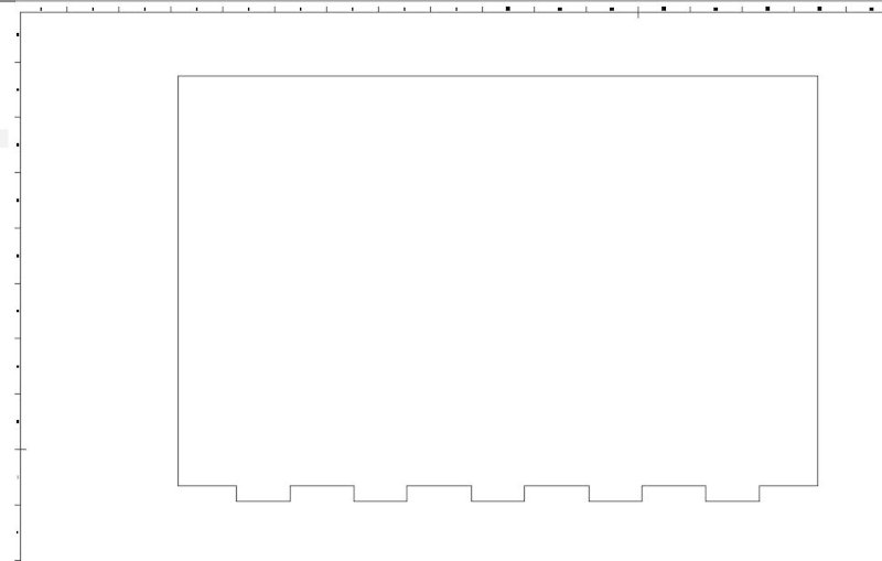
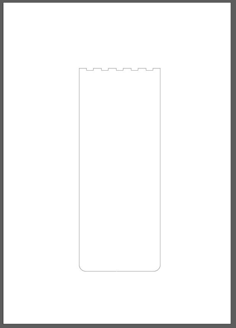
Open Drawing (from Design) to display the image of each element in a template.Fusion360 only has the formats (A4 to A0). Select units in mm.
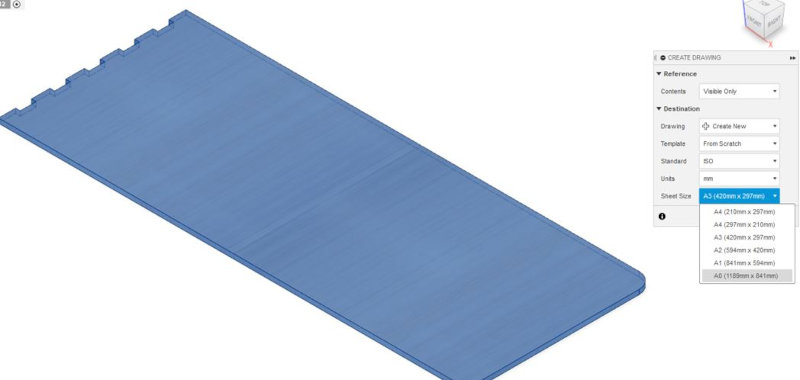
When selecting 1: 1 scale, the model is too large and falls outside the template frame.
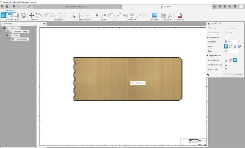
Change to scale 1: 2 so that the piece enters the template.
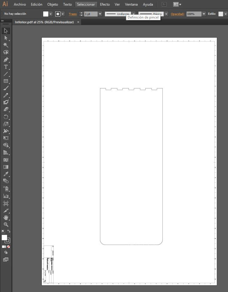
Then the file (OUTPUT - Output DDF or Output Dwg) is exported.
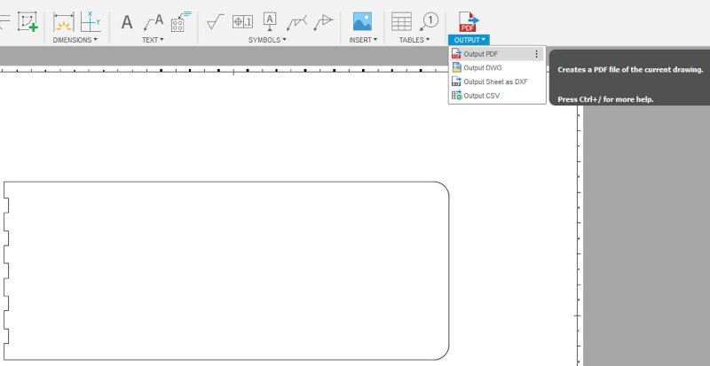
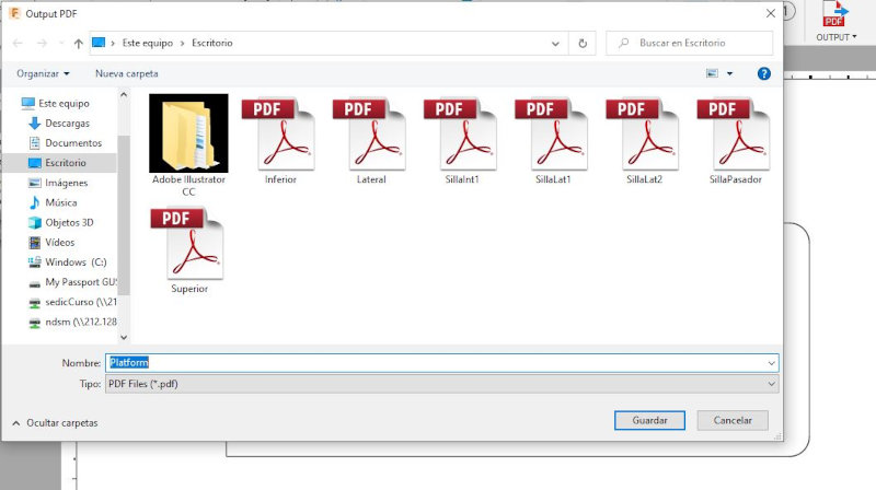
I recommend doing it in .pdf to open it in Adobe Illustrator.
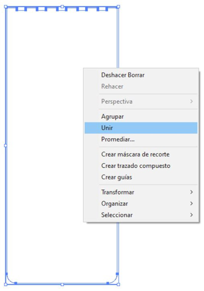
Open Adobe Illustrator and load the .pdf file to generate the vectorized image. Then right click on the entire model and click on (drop clipping mask).
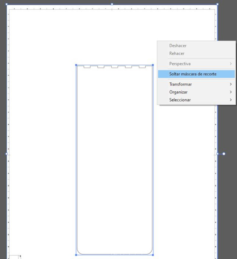
Delete the model from the template and leave only the part model. Select (Join) to join all the lines in the image.
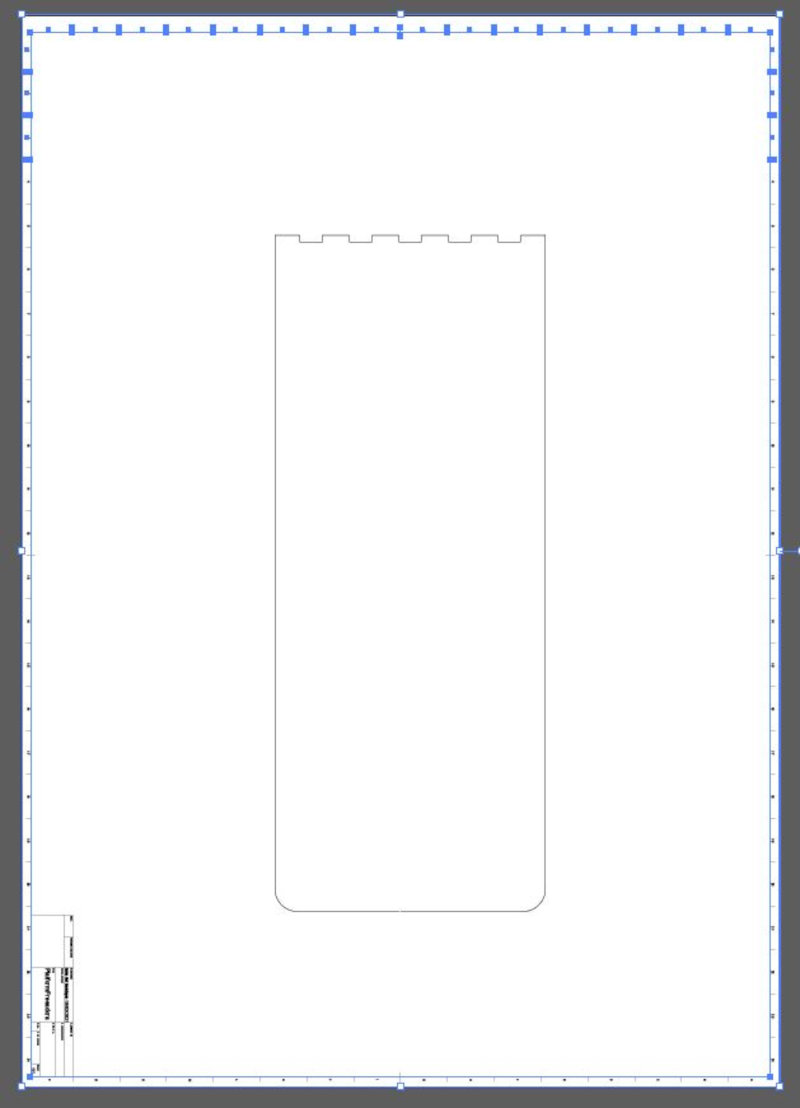
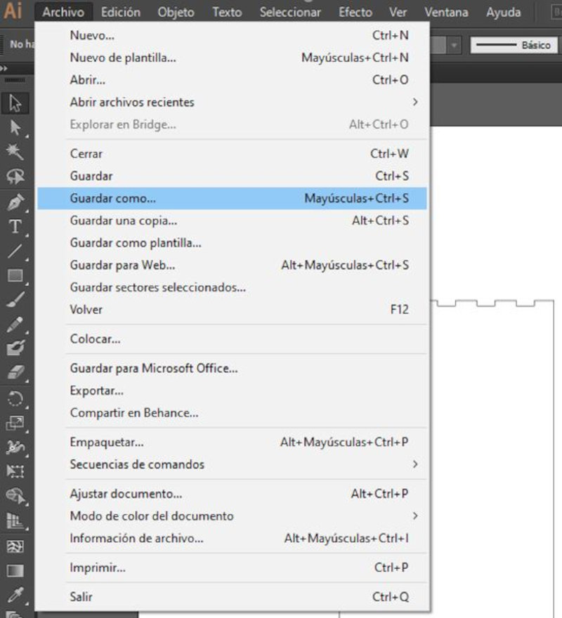
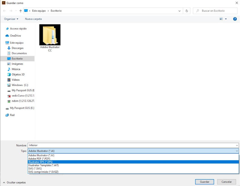
Save the file (Save As…) in Encapsulated PostScript (.eps) format.
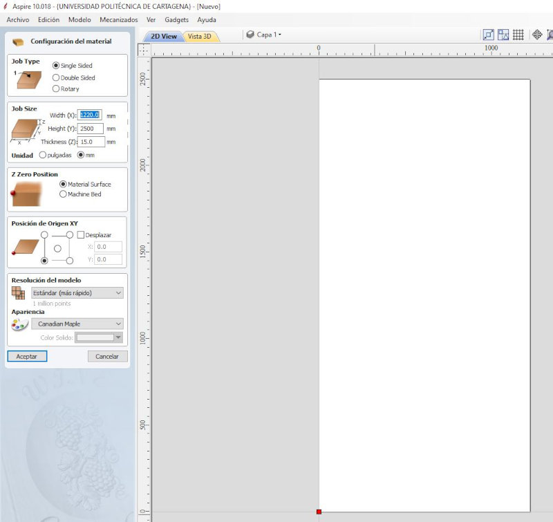
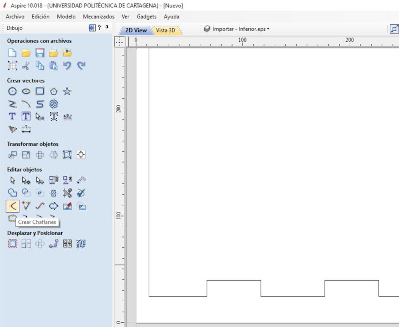
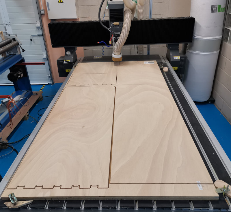
Open the milling machine program (Aspire 10.018).

Edit the "Material Settings" values according to the dimensions of the wood you are going to use. In my case it is a DFM wood (1200 x 2500 x 15 mm). Click OK.
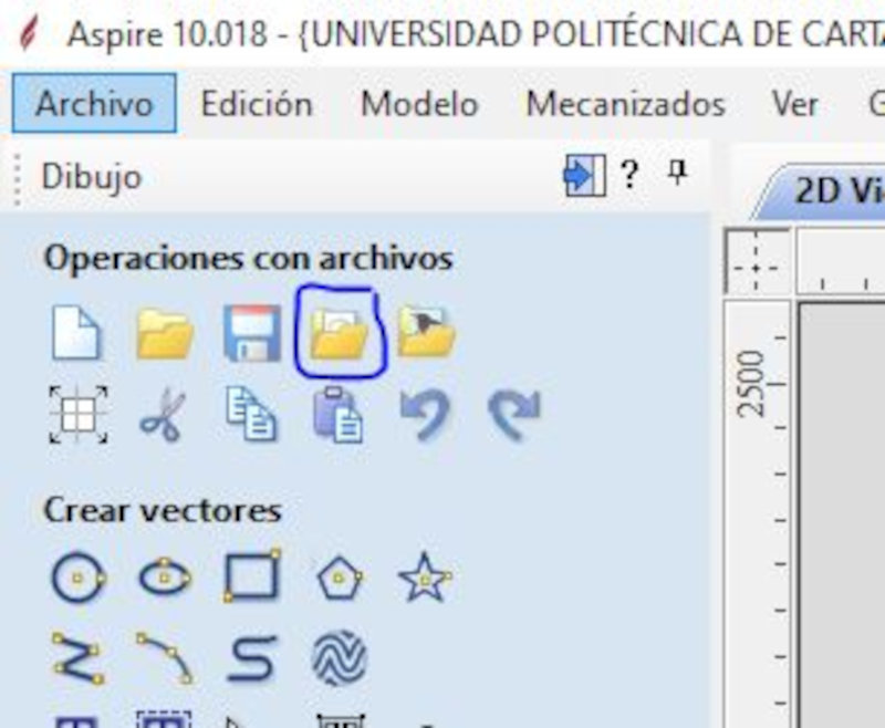
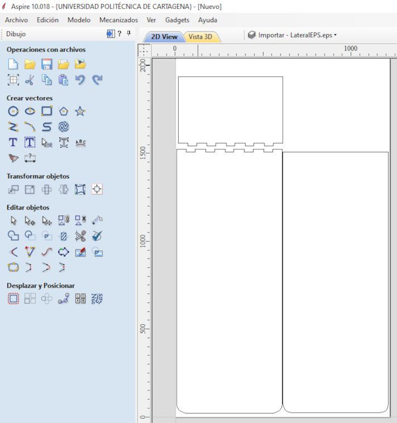
Select the icon (Import vectors from a file) and select the files (.eps).
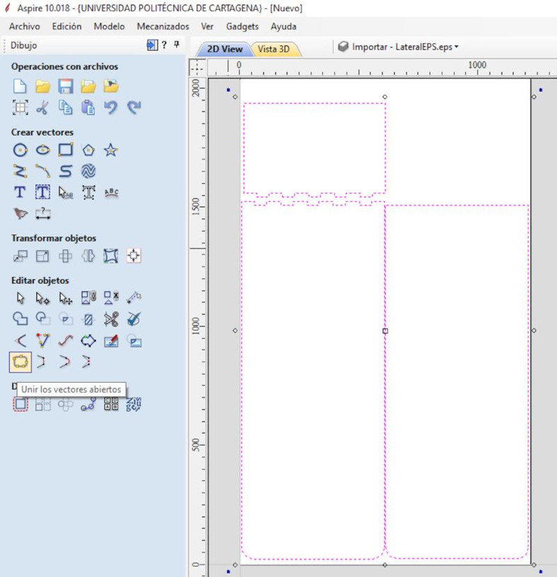
Join the open vectors.
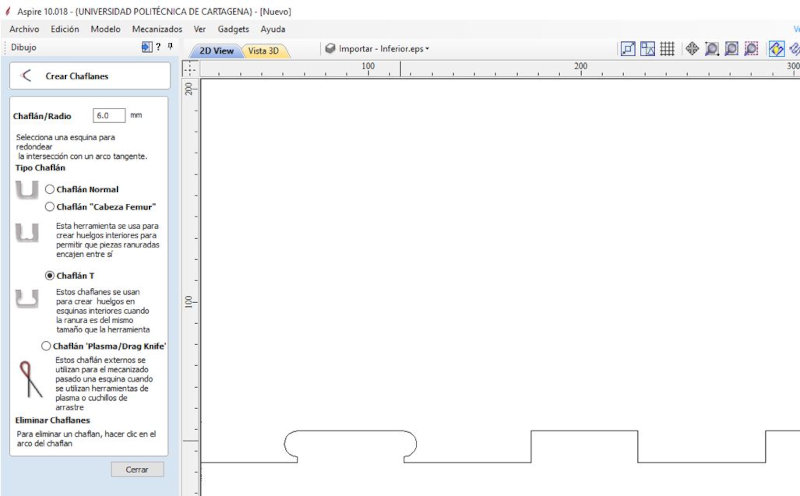
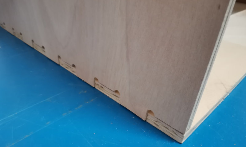
Select the (Create Chamfer) icon.
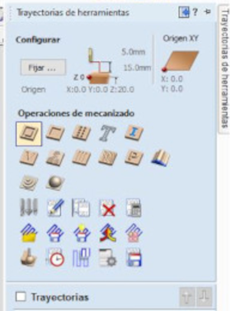
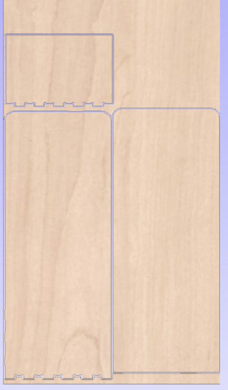
In Toolpath, select from the Machining operations the option (2D Profiling Strategy). The thickness of the wood is 15mm (I select 18mm to go through the wood until it reaches the sacrificial material) and the milling tool is 6mm for wood.
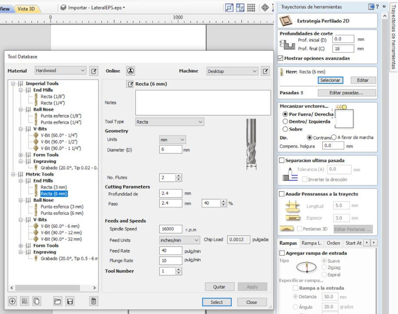
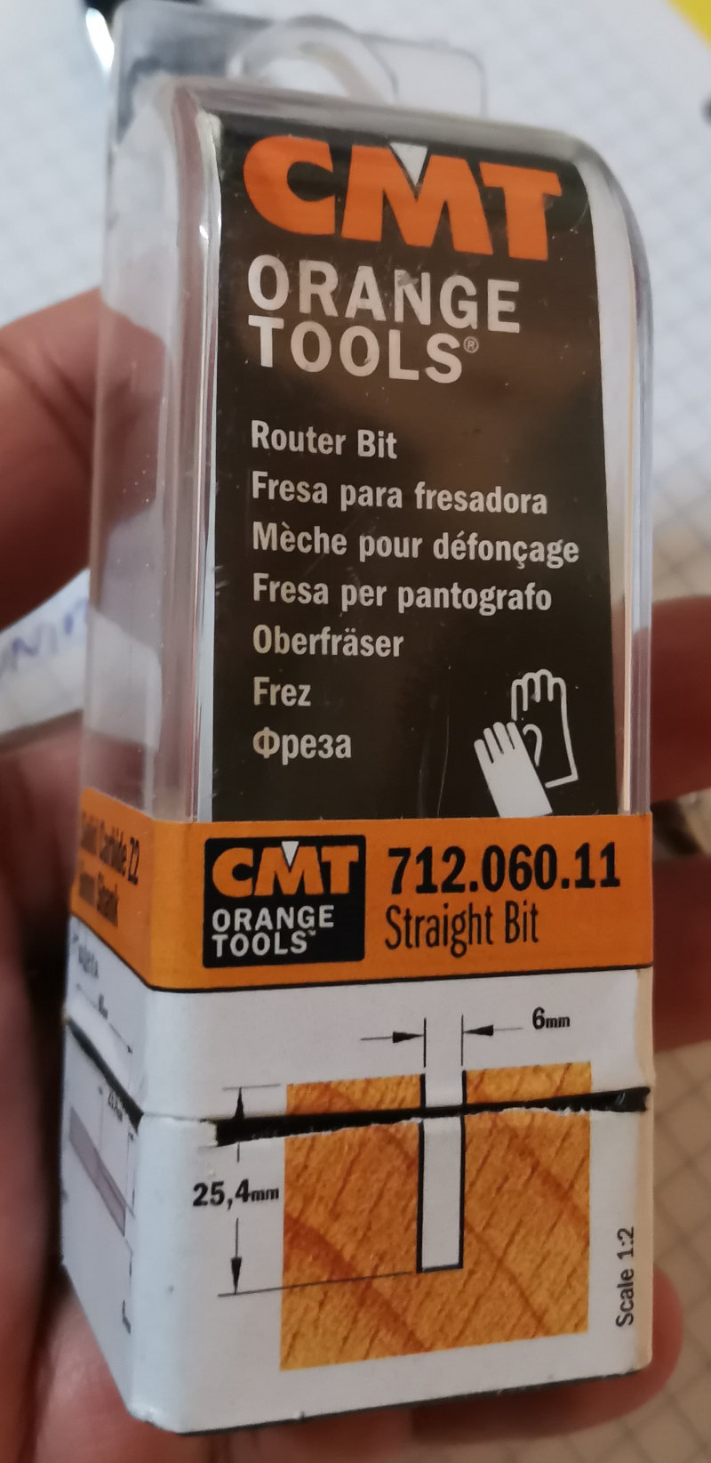
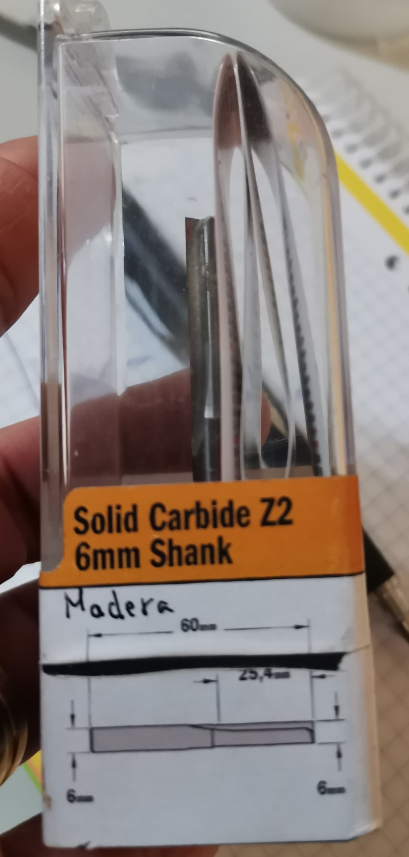
Use a 6mm wood drill/router bit.
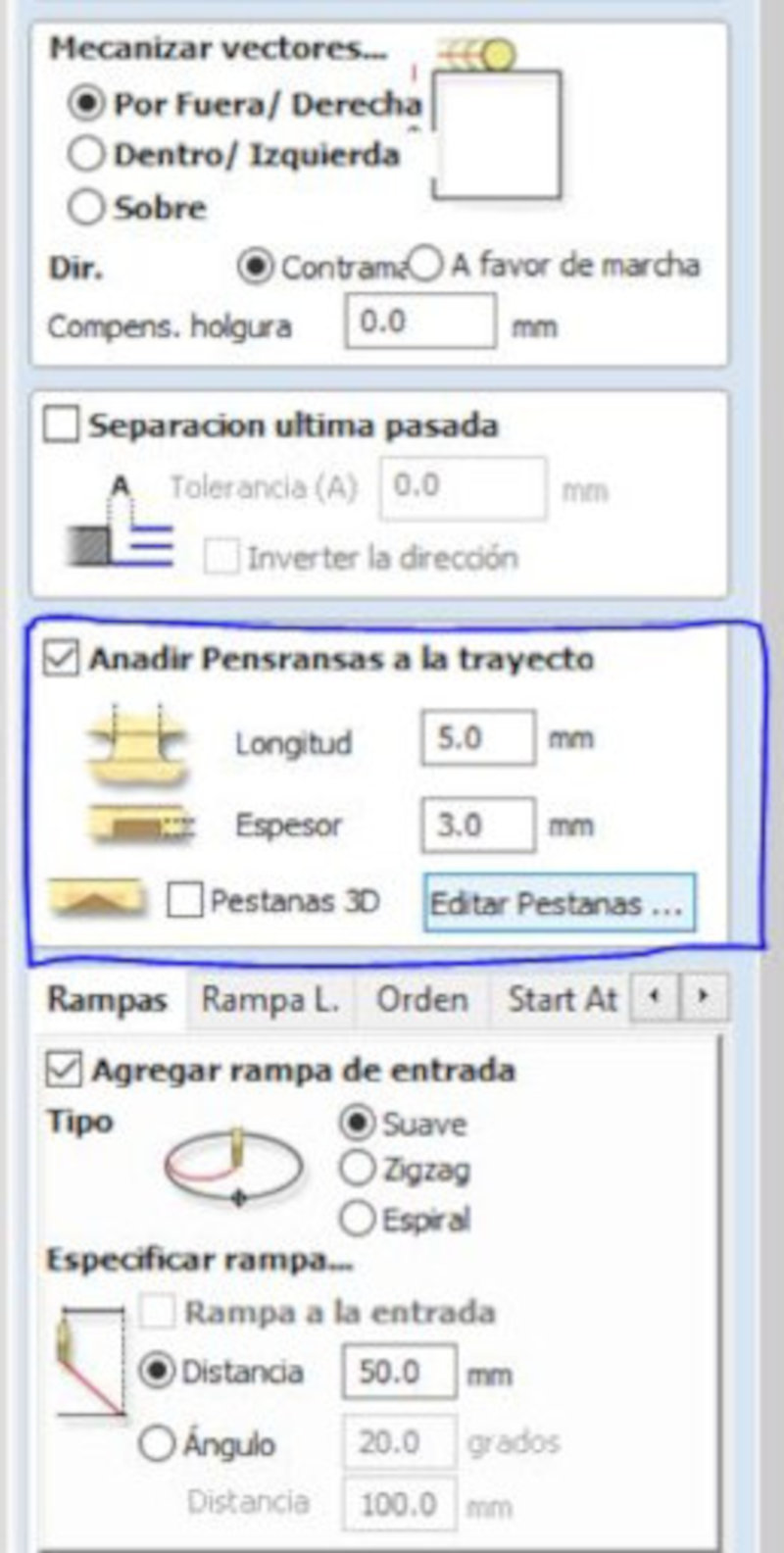
In (Machining vectors ..) select “Outside / right” and Add Pensransas to the Path. Add “smooth” entrance ramp at a distance of 50mm.
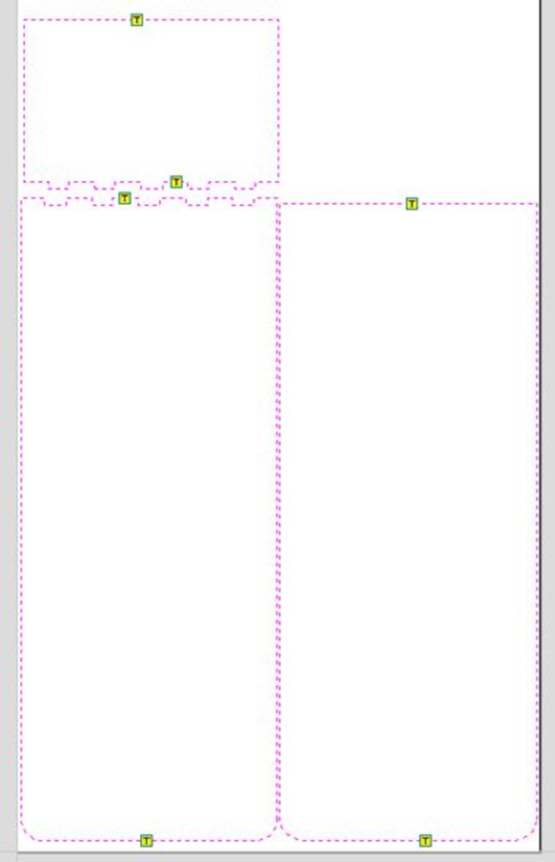
Simulate all paths.
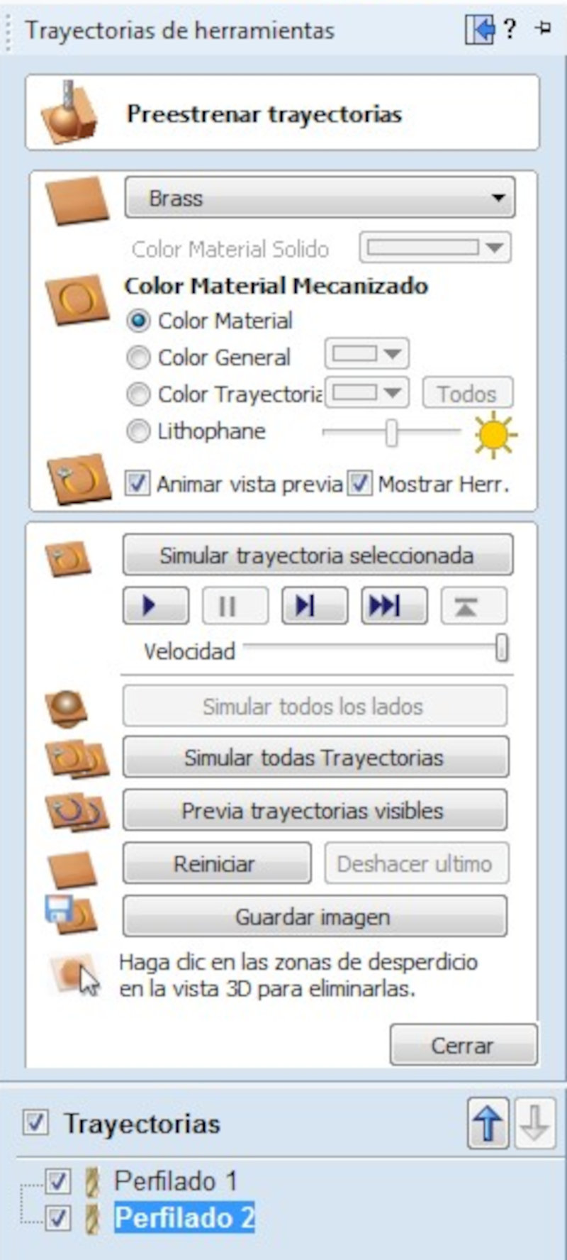
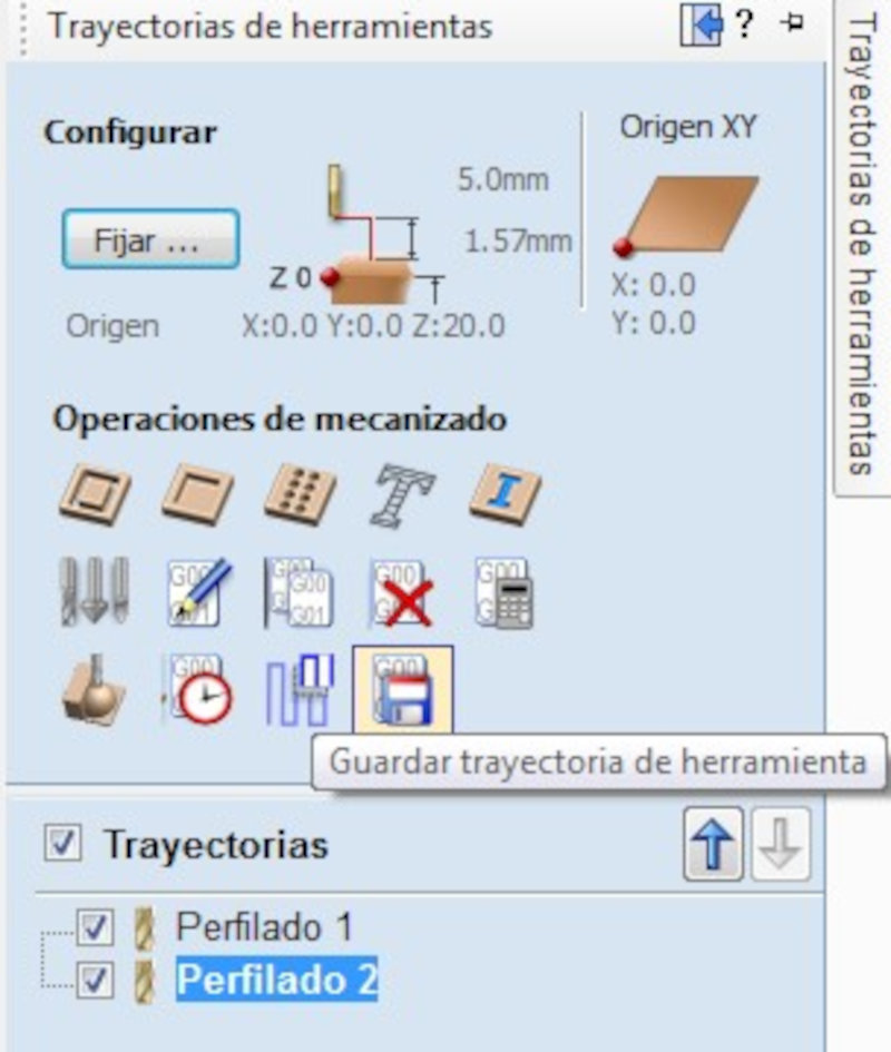
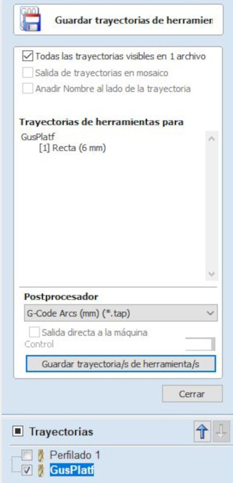
Save toolpath. Save to usb memory in (G-Code Arcs (mm) (*. Tap) format.
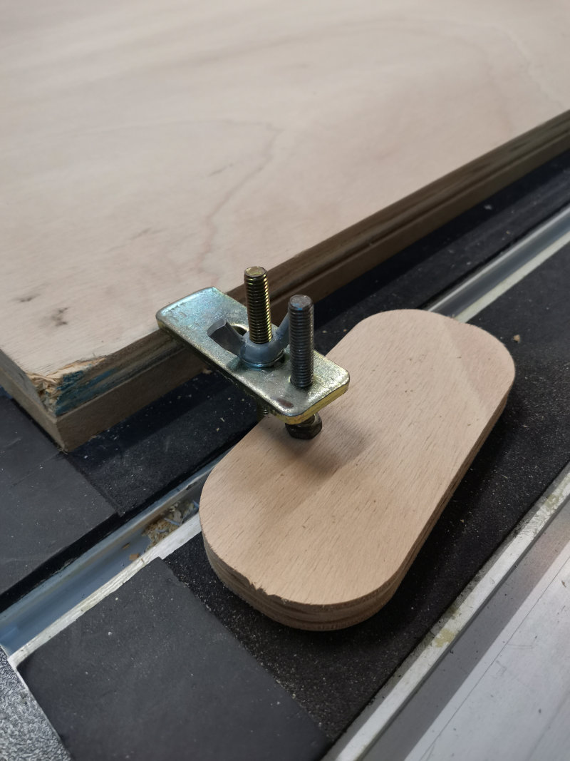
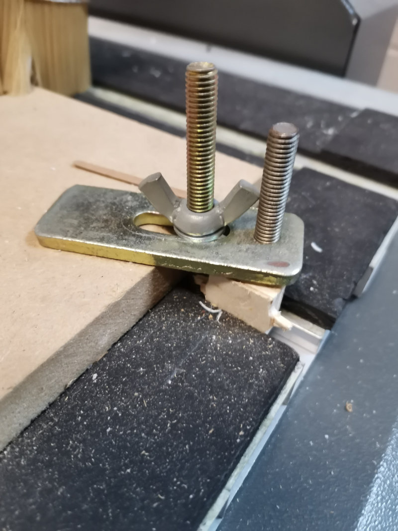
Place the wood in the Barcenas CNC Milling Machine. Put the wood fasteners.
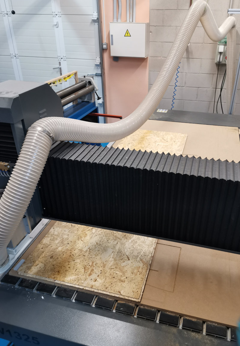
My colleague Álvaro Macian fabacademy 2020 made the calculations of the feed and RPM speeds of the BCNBarcenas with the wood material. Taking these speeds as a reference, I increased the values without finding differences in the result of the cut finish. The values they used were: RPM speed = 18,000 RPM and feed speed = 10,800 mm / min.
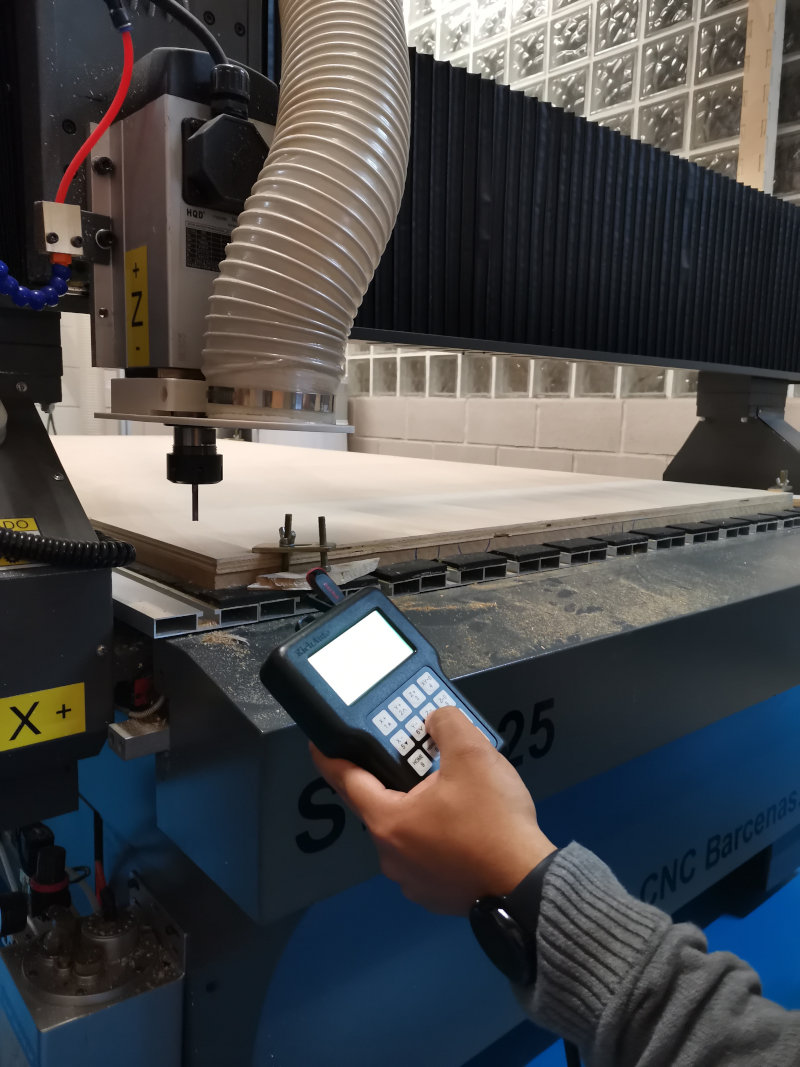
Move the router head to the home axes (X, Y, Z) and adjust the X = 0, Y = 0 and Z = 0 axes according to the location of the wood.
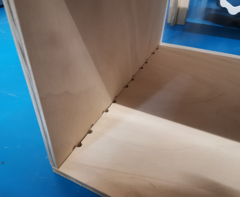
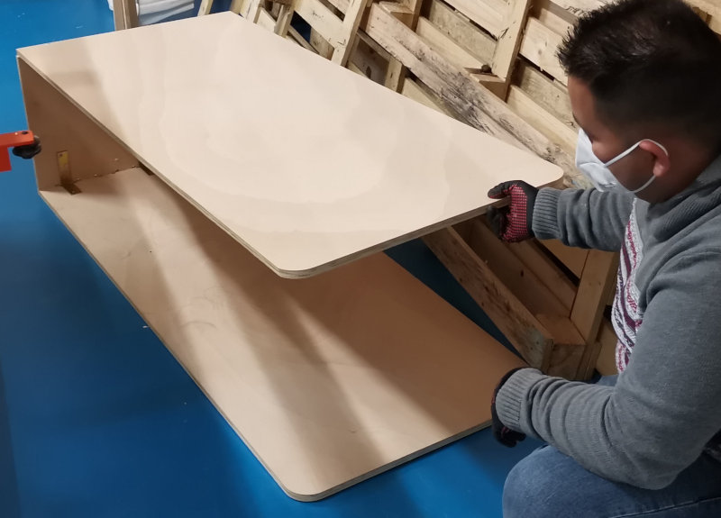
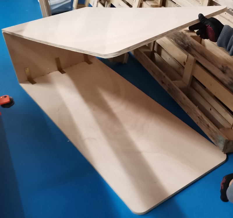
This first design of the platform needs modifications to make it more resistant. I am going to place wooden slats (44mmx44mm) to reinforce the platform. My colleague Juan from the SAIT-UPCT mechanical workshop helped me cut the slats.


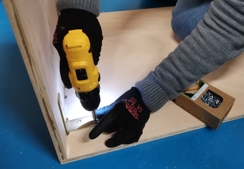
I started the assembly of the slats on the platform, so I had to disassemble it again to screw the slats to the platform with wood screws.


I also realized that the side board of the platform had to be modified in height since it would include the wooden slats. So I had to modify the design files and re-mill that part.

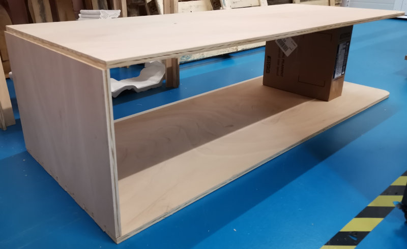
Now if I started to reassemble the platform with all its pieces and slats.


Position the linear actuator clamping system.

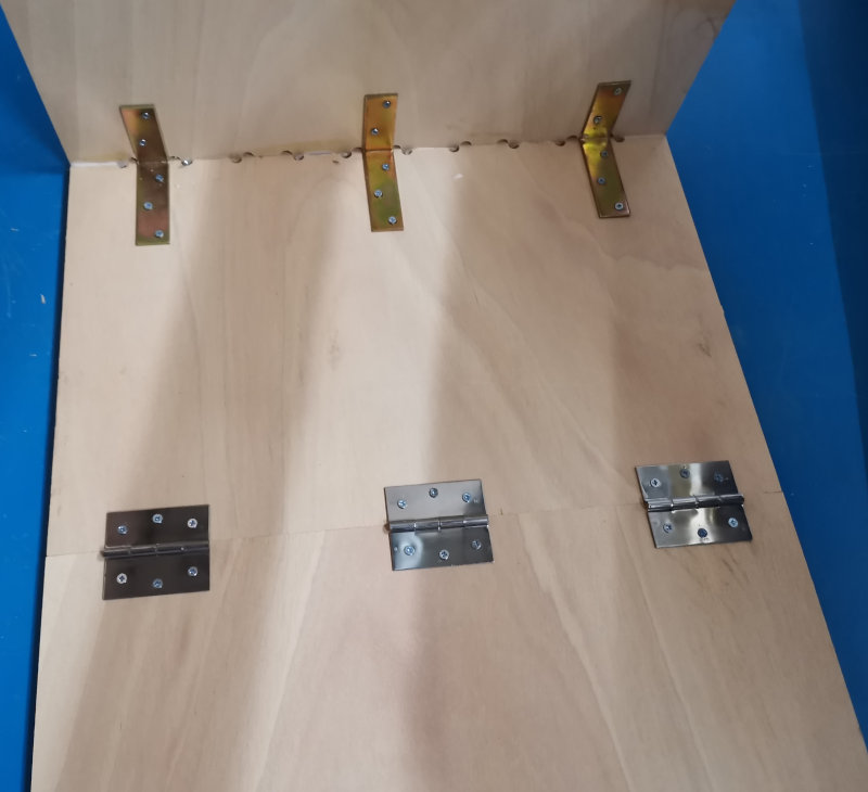
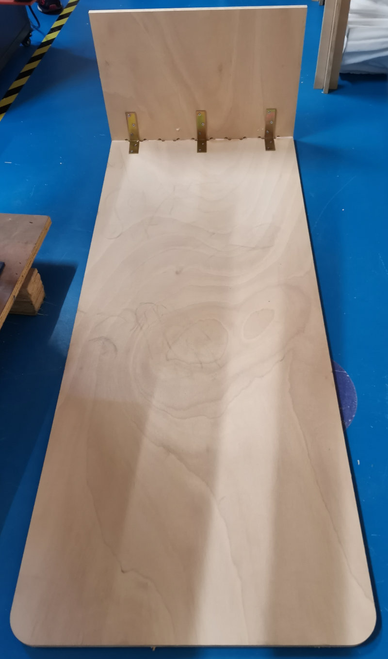
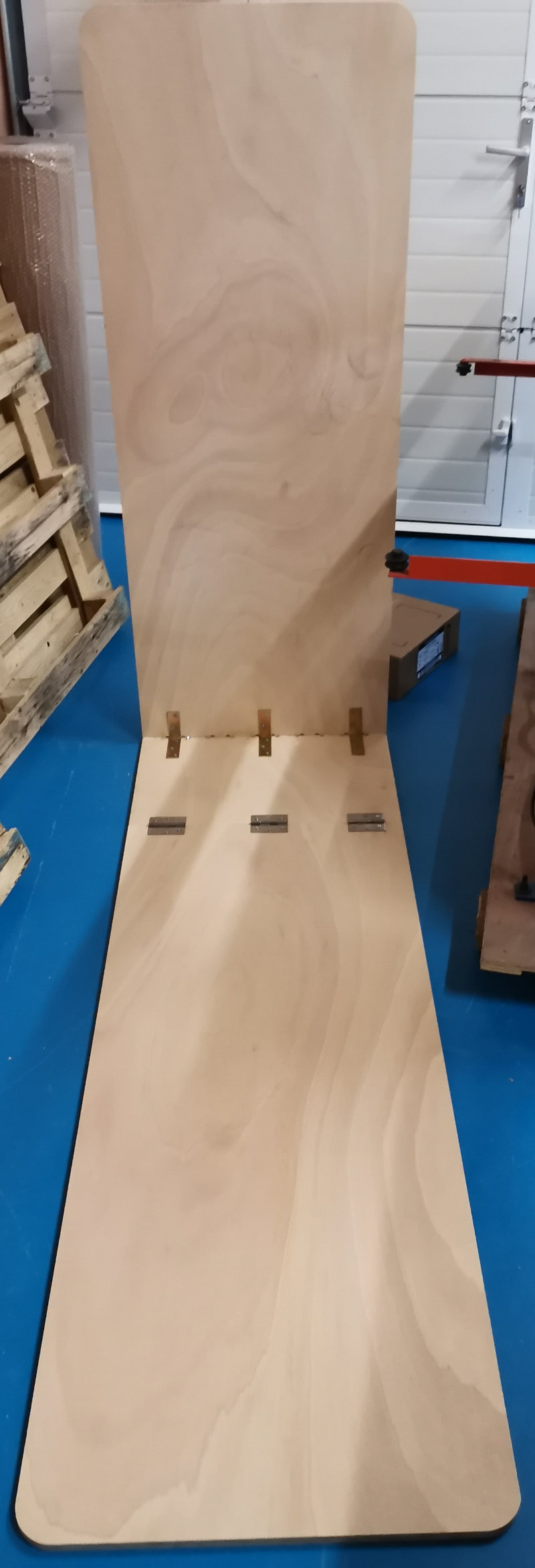
Assemble the top to the side using the hinges.

This support is a critical point when it comes to resisting the weight of a person, I have decided to put a horizontal slat and place the hinges to make the platform more resistant


Now I am going to screw in the fasteners of the linear actuator.


When I got on the platform I have noticed lateral movements of the platform and a bit of instability. I have decided to apply wood glue to the entire deck, I will have to disassemble it again.


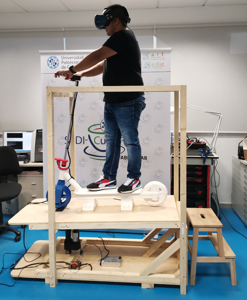
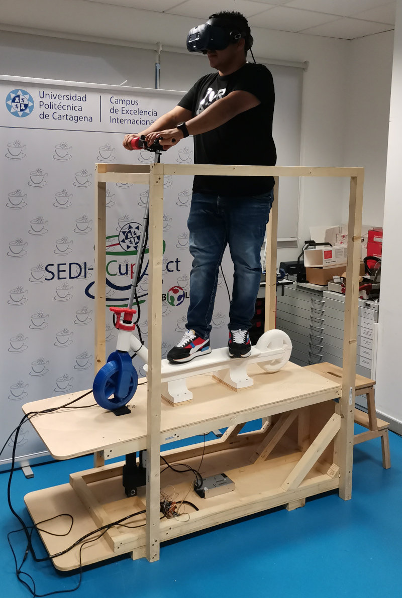
The height is considerable and if the user uses VR glasses, they could fall. Install some safety rails with wooden slats, which also give the platform a little more stability and rigidity. I have also put a wooden ladder so that the user can access it more easily.

My files Platform
2. ELECTRIC SCOOTER MAIN STRUCTURE
Take measurements on a xiaomi scooter
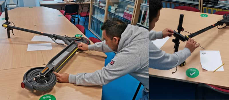
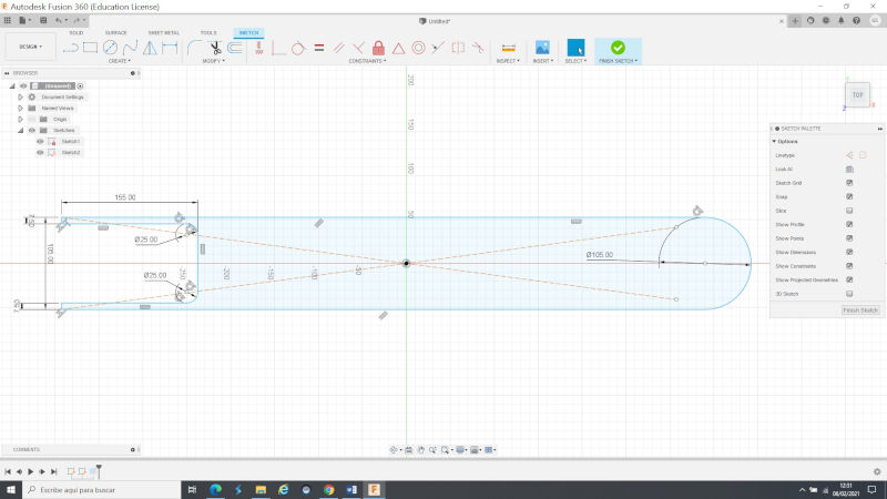
Design Electric Scooter in Fusion360
Website Fusion360. I have a University account to use Fusion360 Student where I design the 3D model of the electric scooter. Activate the DESIGN icon and select a work plane to use the Sketch tools.
My files Electric Scooter
ElectricScooter(.f3d) Fusion360
Printing Electric Scooter
I printed the scooter on the Discovery large format printer.

I have used the Premiun PLA, which is a much stronger PLA with better mechanical properties so that it can withstand the weight of a person. Each coil is 4 kilos, for the printing of the scooter you need 9 kilos.

The printing parameters are:

I have wanted to get the scooter in one print to avoid assemblies of the parts but have had several printing problems. Every time the printing failed, I removed the printed part and began the printing again on the layer that the failure occurred, so I was mounting all the sections at the end.

The PLA has peeled off the printer bed.


The printing layers have also been moved


The failures have occurred because the printer's cooling system did not have good circulation of the coolant, affecting the printing.

Also the extrusion nozzles were clogged preventing the filament from coming out. My colleague Hector Flores has had to repair these faults on several occasions.

The support material is difficult to remove.

And finally, the printer's cabling caught on to the structure that was being printed, breaking the cables throughout the entire system. This repair has not yet been possible


To take advantage of the pieces, glue together the two pieces that came out best.

Use the extra strong glue “DX1 glue”.

The other top pieces that I was missing, I printed on the Ender printers.

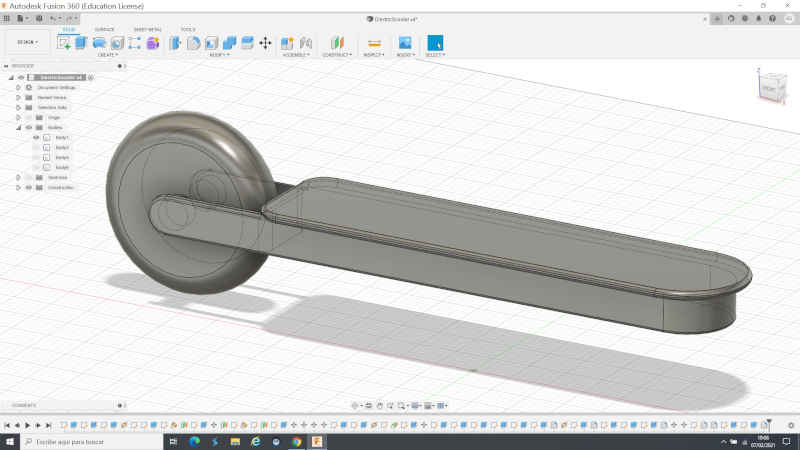
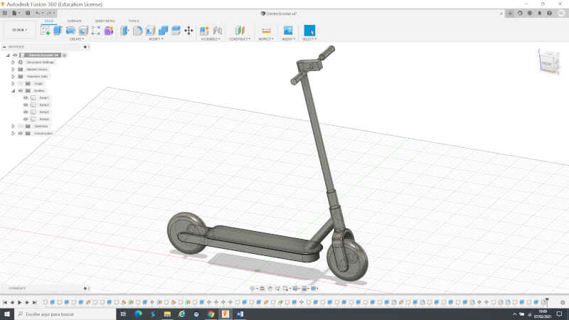
The final result of the structure is as follows:

My files Electric scooter base
Electric Scooter Base for Discovery printer (.stl)
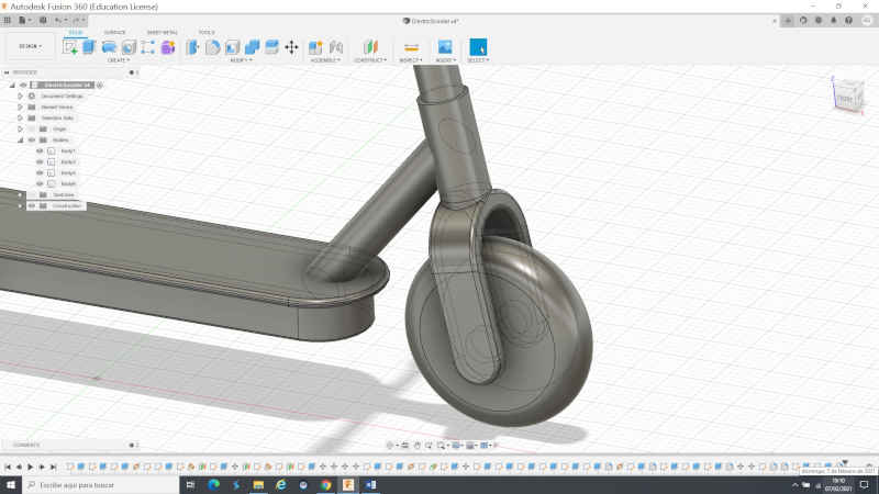
Front wheel
I designed the front wheel with the structure of the scooter in fusion360, I export the .stl file to print it in 3D.

The front wheel was printed in PLA with the SigmaxR19 printing that uses a version of Cura “BCN3D Cura” with the parameters already configured. The advantage of this printer is that it uses dual print heads and allows you to print models that will not fit on an Ender.


My files front wheel
front wheel print file SigmaxR19 (.gcode)
POTENTIOMETER SUPPORT / STERRING HANDLEBAR
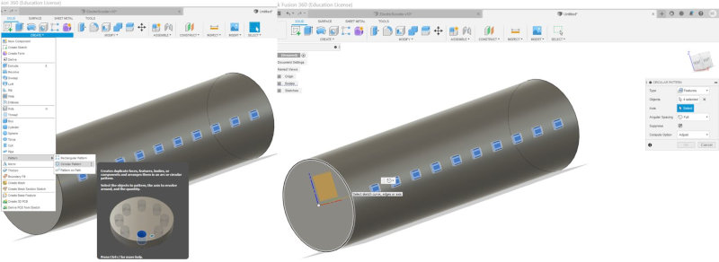
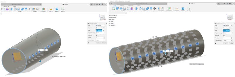
To get the data for the direction of the handlebar, I am going to use a potentiometer that I will install it on a gear holder connected to the aluminum tube to obtain the turning values. I have designed the support and gear system in fusion360.

To design gear1, first enter TOOLS and activate ADD-INS, Select SpurGear and then RUN.

A window will appear with the parameters to create the gear.

For gear1 modify the parameters.

Extrude a bracket with adjusting screw for the gear set screw.

Gear design2 for potentiometer and export in .stl format


Open CURA and import the .stl models to send to the Ender3 printer


Print Properties in Ender3.

Print all parts of the handlebar steering detection system

Export in .gcode for printing.

I have used PLA for 3D printing.

Arduino Potentiometer Program
I have followed these tutorials to read a potentiometer signal with Arduino:
- https://programarfacil.com/blog/arduino-blog/el-potenciometro-y-arduino/
- https://www.luisllamas.es/lectura-de-un-potenciometro-con-arduino/


I have loaded another program that prints the values of angles between -90 and 90 degrees through the serial port.


My files potentiometer
gear1 potentiometer support (.stl)
gear2 potentiometer support(.stl)
print file Cura the pieces of the potentiomet support (.3mf)
potentiometer support structure (.stl)
Potentiometer arduino programm (.ino)
UPPER HANDLEBAR SUPPORT
I'm going to use a button with an LED to indicate when the scooter is turned on and connected.

The button will go over the top mount of the handlebar headset, which links the handlebar tube to the main steerer tube. Design in Fusion360 the support.

I use Cura to print it on an ENDER printer, I use PLA in black.


For programming the led button I have followed this tutorial:


My files upper handlebar support
Button/led arduino programm (.ino)
print file Cura the upper handlebar support (.3mf)
upper handlebar support print file (.gcode)
HAND BRAKE
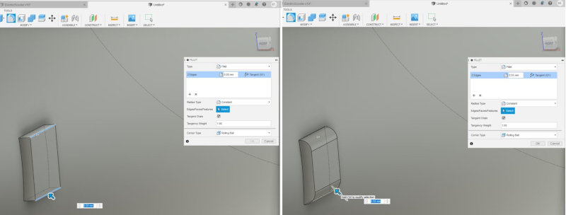
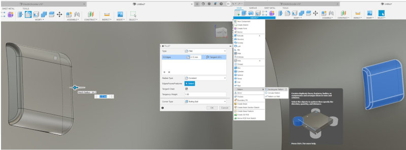
For the design of the brake lever I am going to use a hall effect sensor to obtain the brake actuation parameter. This sensor records data when a magnetic field is activated by approaching a magnet. The design of the brake lever was made in FUSION360. It is composed of two pieces:
A main piece “Brake Lever” that is screwed to the handlebar tube and houses the hall effect sensor.

and a secondary piece "clamp lever" that is assembled by means of a link to the Brake Lever. It houses the magnet and incorporates a spring to keep the system always open.


Print using Cura and ender3 pro.


I have printed the clamp lever again because the brake travel is not enough, so I have to modify it, I have felt frustrated but I will keep going because I am a warrior and I will never give up.


The HALL EFFECT SENSOR I used is: Allegro MicroSystems A1324LLHLT-T .


I use the hall effect sensor for the scooter's throttle and for the hand brake. Design of the plate for the sensor with the Eagle program.


He placed the sensor in the fixed support and the magnet in the movable support "clamp"


Arduino program for the sensor. When the magnet is in the furthest part the value is: 100. As the magnet approaches the sensor, the value decreases.


My files hand brake
Hand brake arduino programm (.ino)
Hall effect sensor board design project in eagle(.epf)
Hall effect sensor board design boar in eagle(.brd)
Hall effect sensor board design project in eagle(.sch)
Print file Cura the brake lever support (.3mf)
Print file Cura the clamp lever support (.3mf)
Clamp lever support print file (.gcode)
Brake lever support print file (.gcode)
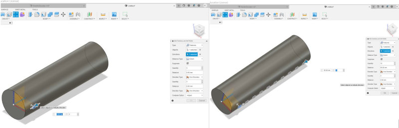
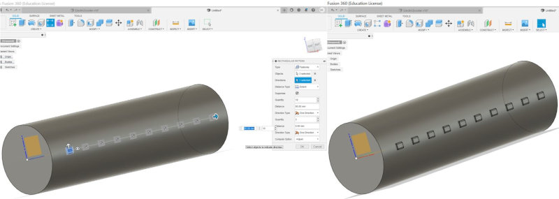
THROTTLE
For the throttle design I am going to use a replica of the plate and hall effect sensor equal to the brake system to get the throttle actuation parameter. This sensor records data when a magnetic field is activated by approaching a magnet. I did the design in Solidwork, although I handle Fusion360 better, I wanted to try another design program. The system is made up of three parts:
A fixed main piece that bolts to the handlebar tube and houses the hall effect sensor. It also incorporates a spring to keep the system under tension.

A moving secondary part that houses the magnet.

And a piece that is used as a cover.

Final assembly of the three pieces.

3D printing with CURA / ENDER.

The magnet is inserted and the spring is fitted into the fixed part.

Inside the aluminum tube of the handlebar, the 3 parts are assembled. The hall effect sensor is inserted in the moving part. And finally the cover is put on by passing the cables through its slot.


To program the sensor, use the same program and procedure as for the brake system.


Arduino program for the sensor. When the magnet is in the farthest part the value is: 100. As the magnet approaches the sensor, the value decreases.


My files throttle
Throttle arduino programm (.ino)
Hall effect sensor board design project in eagle(.epf)
Hall effect sensor board design boar in eagle(.brd)
Hall effect sensor board design project in eagle(.sch)
Throttle solidworks projcct (.SLDASM)
fixed main piece throttle(.stl)
moving secondary part throttle(.stl)
Print file Cura the pieces throttle support (.3mf)
SUPPORT FOR MPU6050 SENSOR
I have designed in Fusion the bracket to install the mpu6050 sensor under the “top of the platform”.


I use Cura to configure the printing parameters in PLA on an Ender printer.


Fasten the MPU sensor to the bracket with two screws.

In Interface and applicaction programming week 14 perform the MPU configuration and testing. I install the bracket on the wooden deck.

My files Mpu6050 sensor
Print file Cura the mpu6050 support (.3mf)
Mpu6050 support print file (.gcode)
Testing integrating throttle, handlebar steering, brake and button / led and mpu6050 sensor
Next I do the functional tests of the brake, accelerator, handlebar steering and button / led and mpu6050 sensor. I integrate the three programs into a single arduino program and display the data on the serial port.
Handlebar
Handlebar design
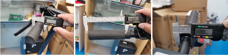
I am going to design the handlebar grip of my final project scooter model using Fusion360.
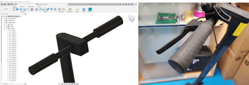
I have followed the tutorial of fusion360 tutorial. to make the model.
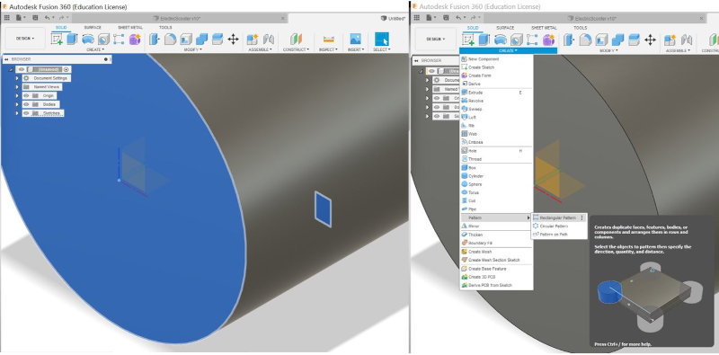
I have noticed that the inner tube of the handlebar was missing, so I extrude a 5mm tube on each side.
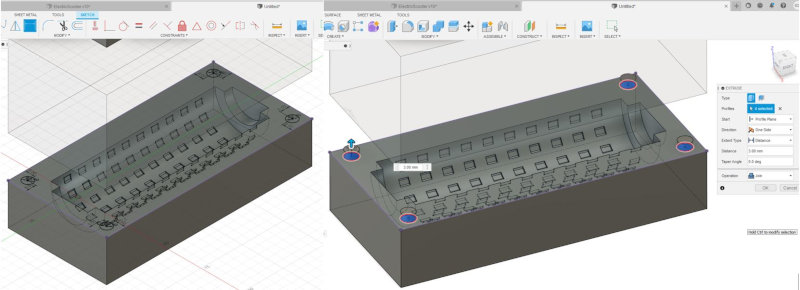
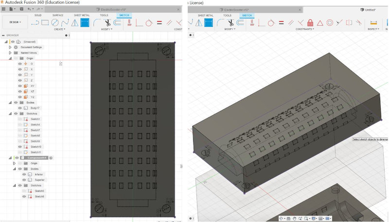
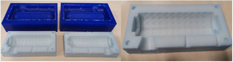
Mold design
I have followed the tutorial of fusion360 tutorial. to make the mold.
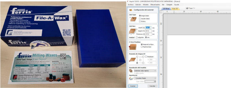
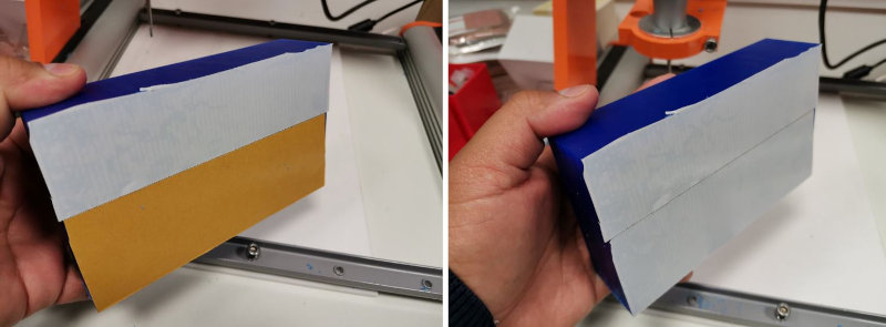
I should point out that the wax block measures 145x85x37mm. So the mold I make should measure less.
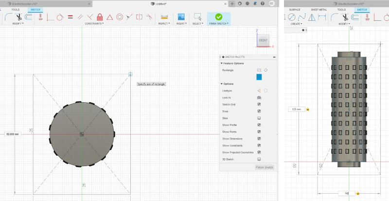
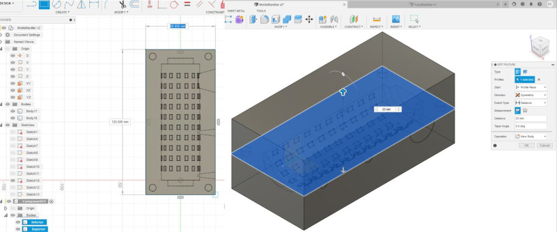
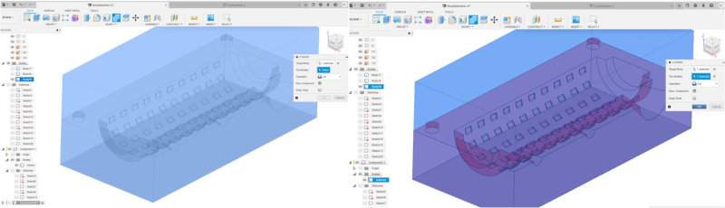
Extrude the mold model in symmetry.
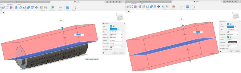
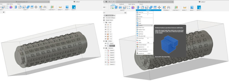
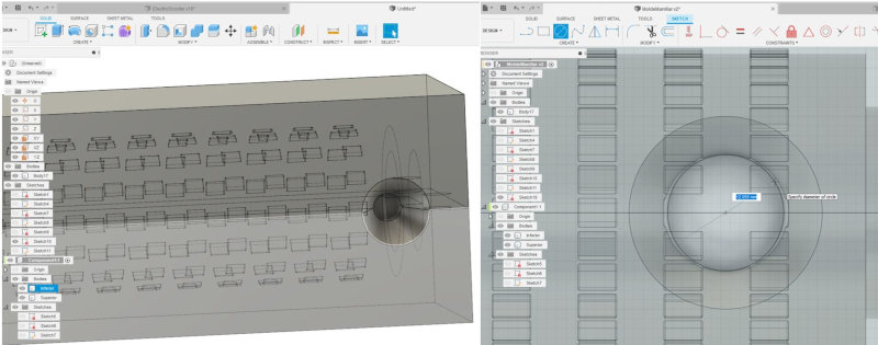
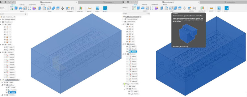
The Target Body: Select the Body2 (Box) and the Tool Bodies: Select the Body1 (Handlebar Handle).
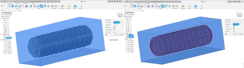
A new component is created.
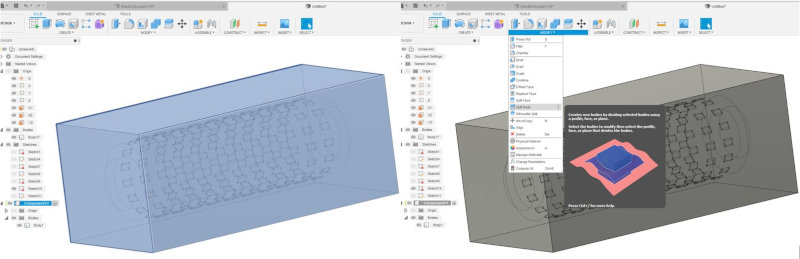
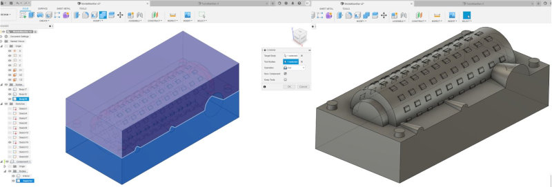
Select the Body to Split (Body1) and in the Splitting Tool (s) (select Origin XY).
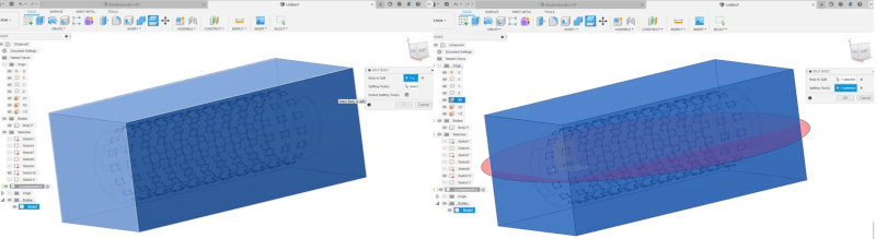
Move the upper section of the mold to see the inside of the model.
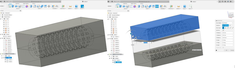
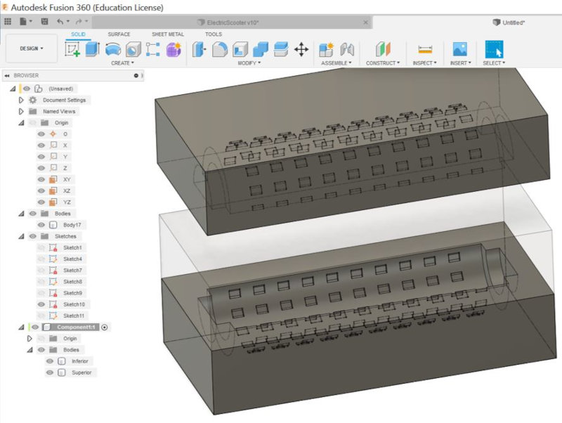
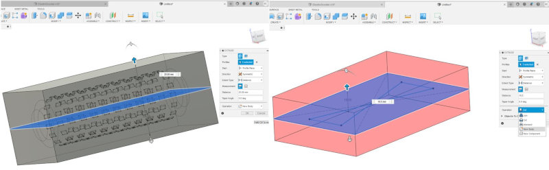
I also move the bottom piece to get it out of the transparent rectangle and to be able to edit on its face. Design the guide sections to fit the two models of each mold.
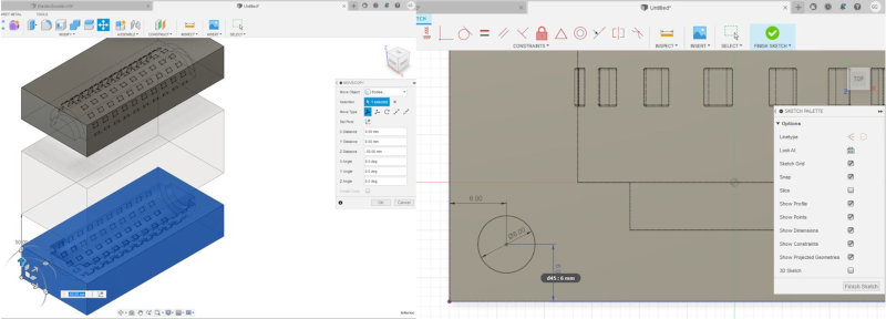
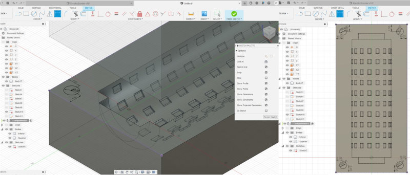
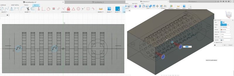
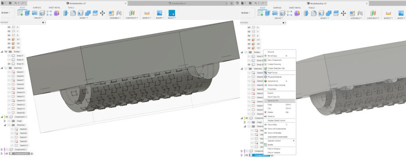
Make the same sketch with the top but with a negative extrusion.

Make the material inlet hole (casting).
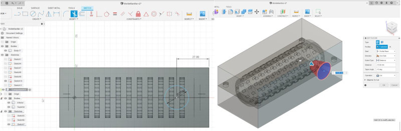
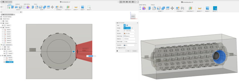
Make the air extraction holes of the molds.
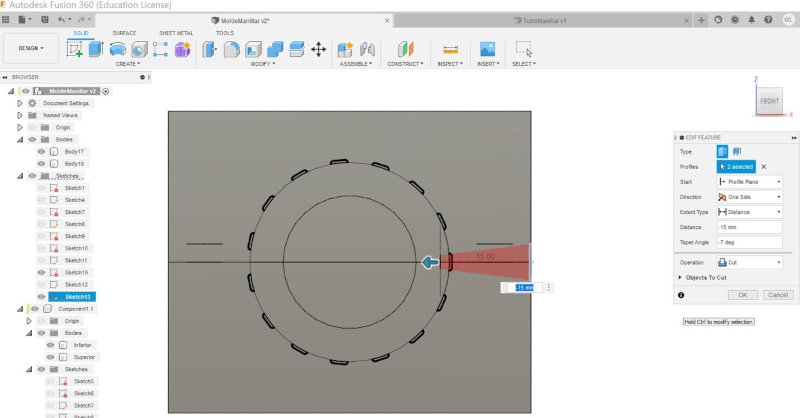
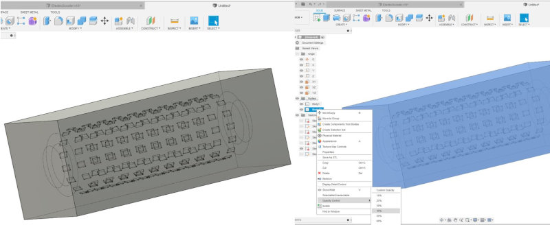
Design the back mold or mold negative.
Create a sketch with the dimensions of the square less than the dimensions of the mold.
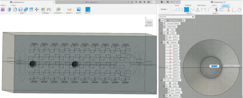
Upper counter mold
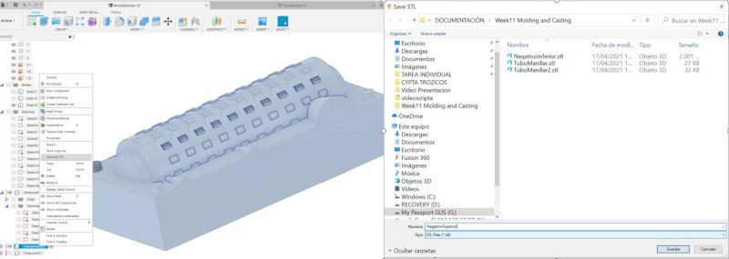
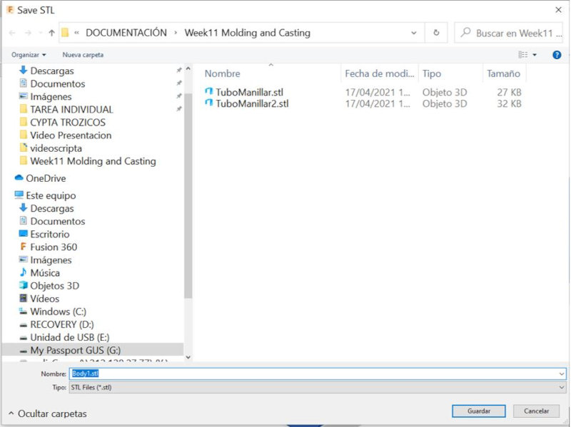
Export in stl the negative of the upper mold.
Lower counter mold
Export in stl the negative of the upper mold.
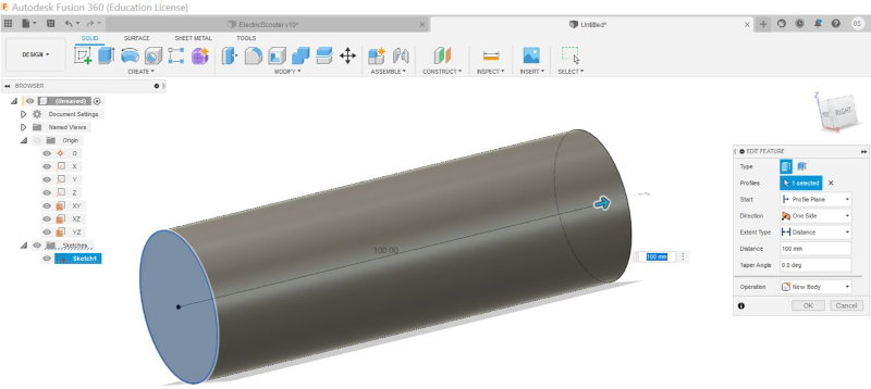
Handlebar inner tube design.
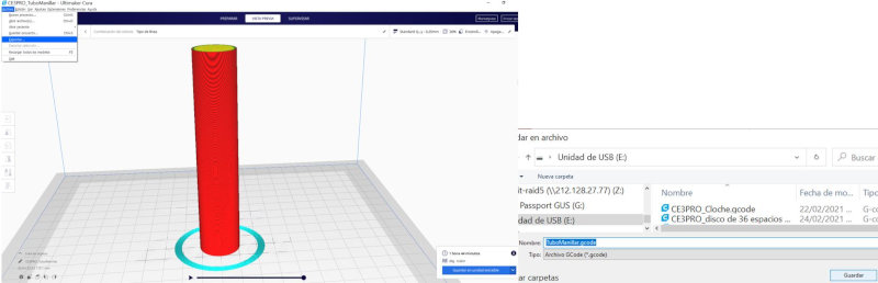
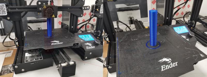
I design the handlebar tube in Fusion360 and export it to the CURA software to print it on an Ender3 printer.
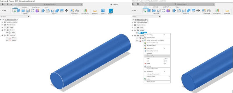
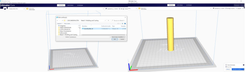
I export the model in .gcode to print it on an Ender3 printer.
COUNTERMOLD MILLING
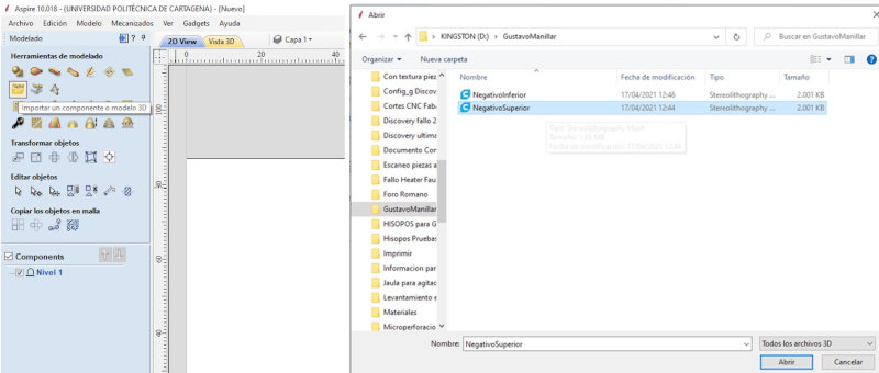
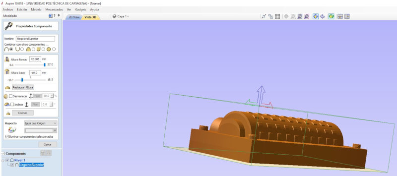
I use Aspire software to generate the 3D milling files.
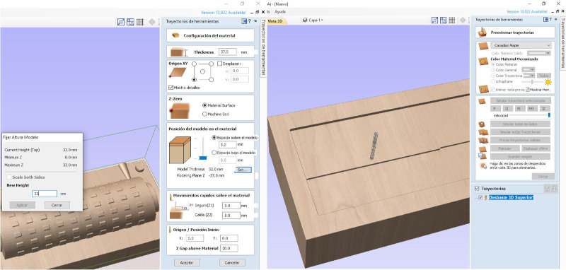
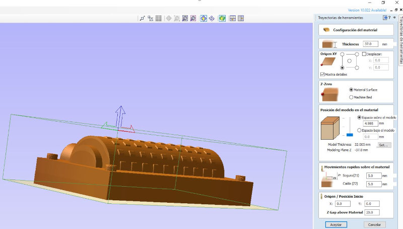
Upper counter-mold configuration
Configure material according to the dimensions of the wax block that I will use for milling.
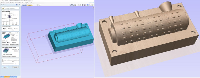
Open in Model tab.
Orient model.
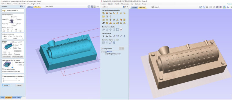
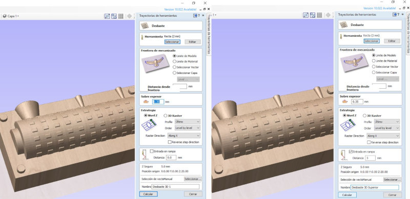
OPERATION STRIPPING and position of the model in the material: 37 (thickness of the material).
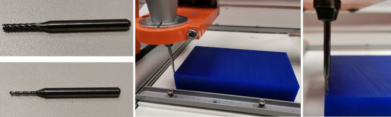
Select tool (2mm bit).
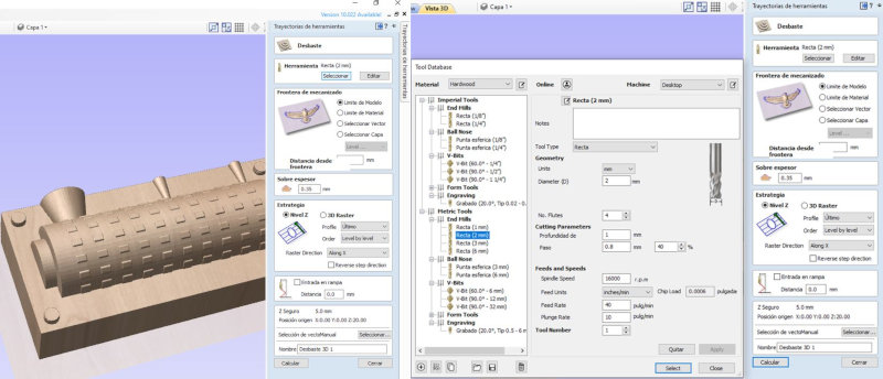
Extra thickness (20% of the diameter) = 2mm the maximum is 0.4, I put 0.35mm. 5mm ramp.
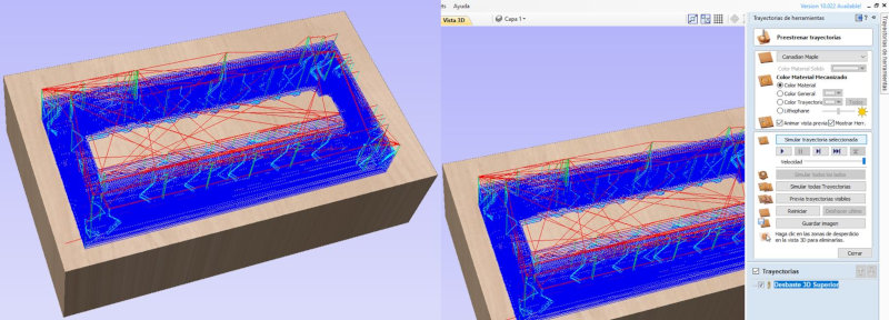
Simulate selected path.
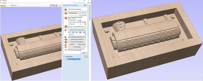
Save File.
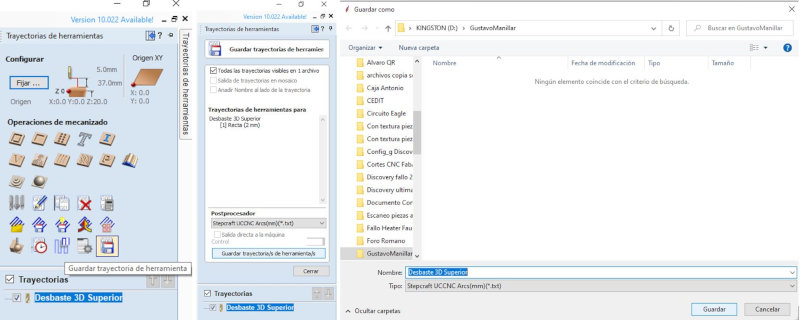
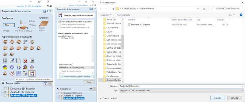
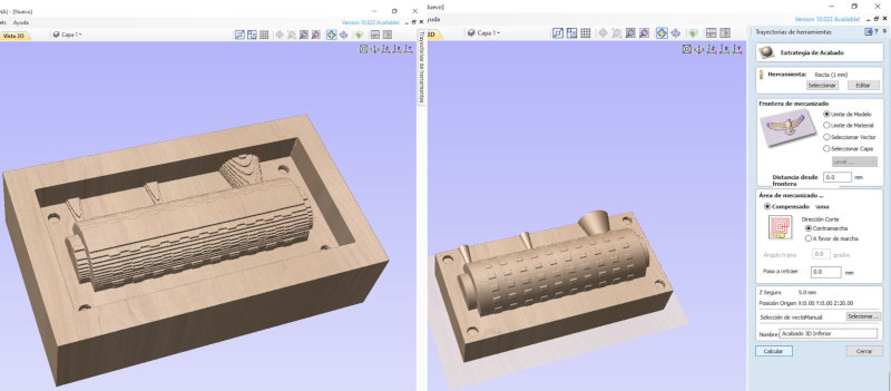
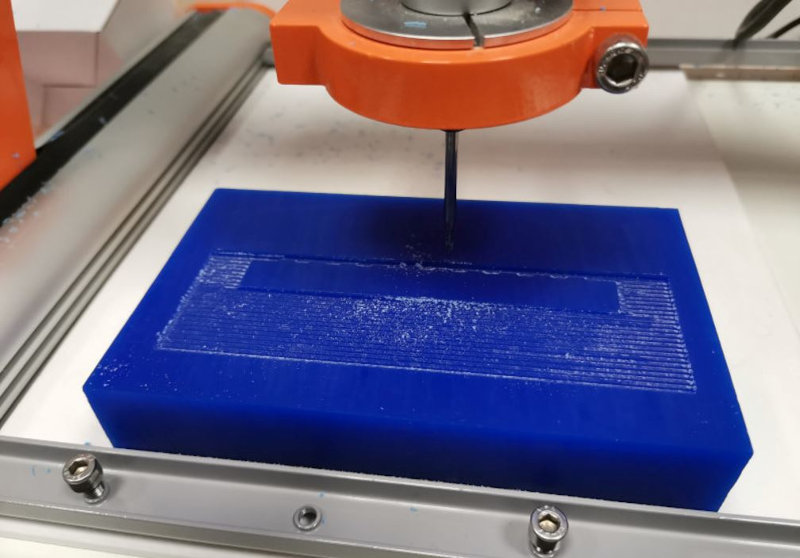
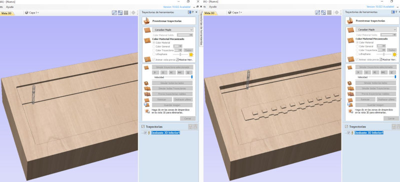
FINISHING OPERATION: Select tool bit 1mm.
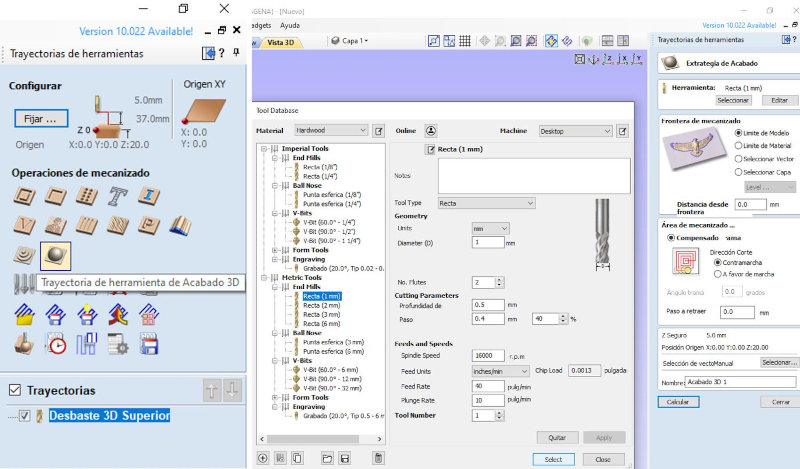
Machining area (Compensated), calculate and simulate all toolpaths.
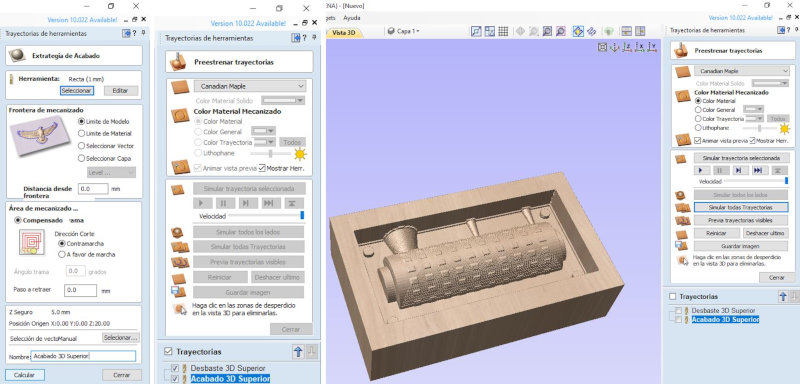
Machining (Screen) and simulate selected toolpaths.
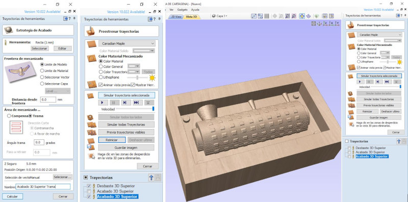
I am going to use offset machining which works better than hatch machining. Save the file.
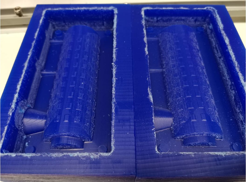
Do the same procedure with the lower counter mold model.
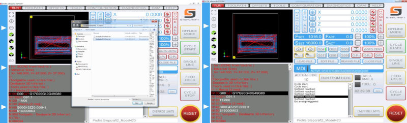
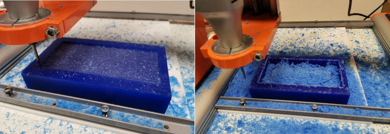
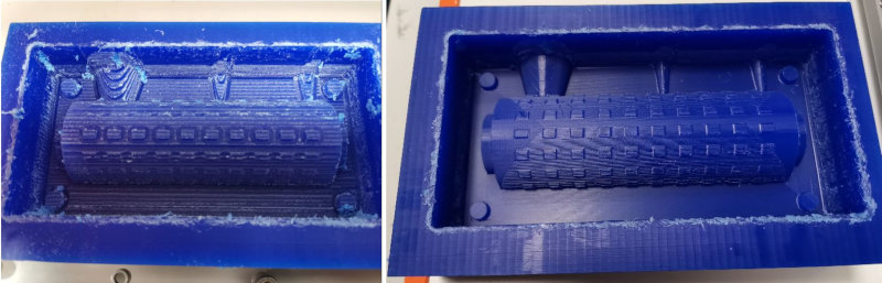
milling with the STEPCRAFT420 MILLING MACHINE
Abrir el programa UCCNC, cargar el archivo .txt. Configurar el x,y,z en mi Origen.
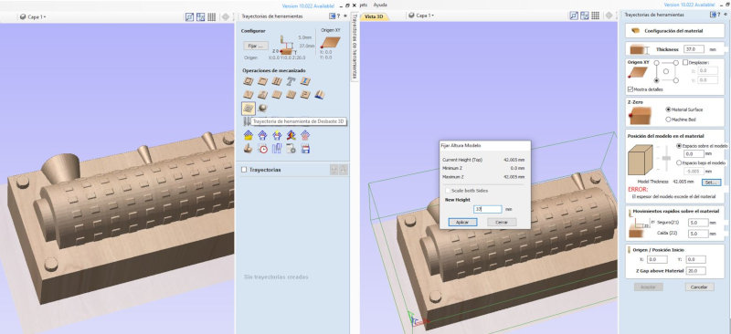
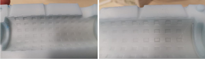
Milling I found an error, I have to lower the model a little when milling.
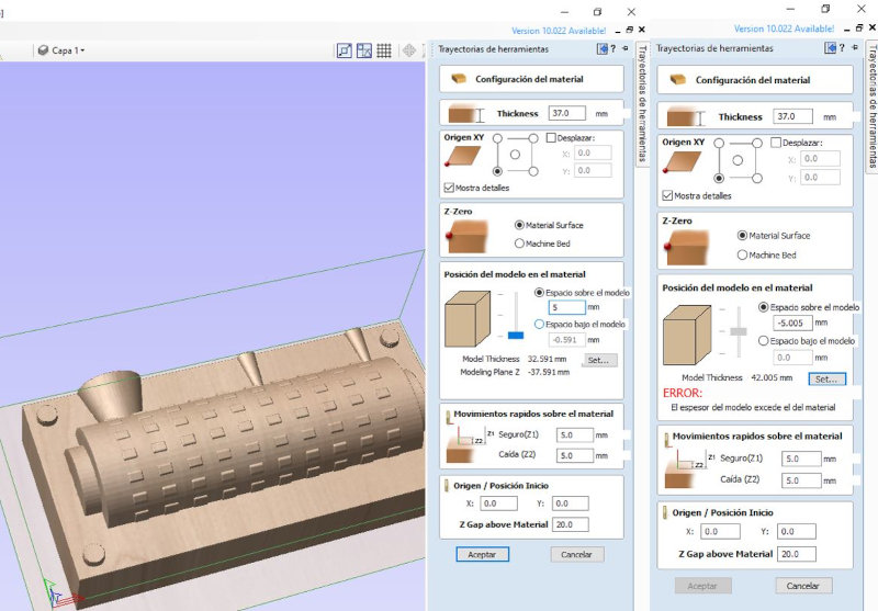
I select 32mm so that the total is 37 of the thickness, at the top there are the 5mm that I want to leave.
Correction in surface milling.
The model is oval, it has a deformation in the Z axis.
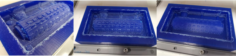
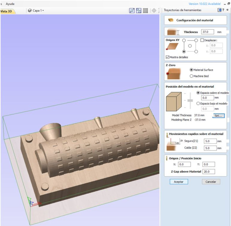
In the Aspire I find a way to lower the model below the surface (5mm) without affecting the Z axis relationship, avoiding the deformation of the countermold.
I re-mill in another wax mold to see the results.
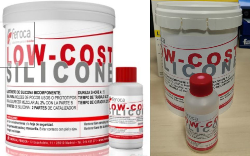
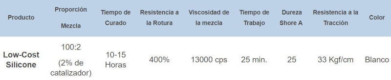
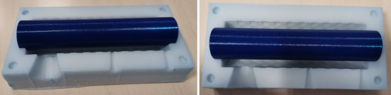
Mold material (Feroca Low Cost Silicone)
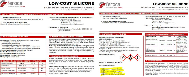
Feroca Low-Cost Silicone is a two-component silicone elastomer (parts A and B) that cures at room temperature, the base (part A) has the appearance of a viscous liquid which, after the addition of the catalyst (part B ), becomes an elastic material. It features exceptional fluidity and good operability. It is recommended for the application of molds for casting of Plaster, Polyester Resin, Polyurethane Resin, Epoxy Resin, Fiberglass, Wax, Soap, Bronze, etc. It is a type of soft silicone rubber with medium viscosity, so if desired you can lower the viscosity using Silicone Fluid. It is suitable for molds with complicated gaps that are difficult to remove from the mold.
Instructions:
- Prepare the box for the mold and the original..
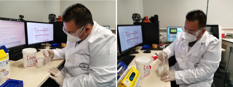
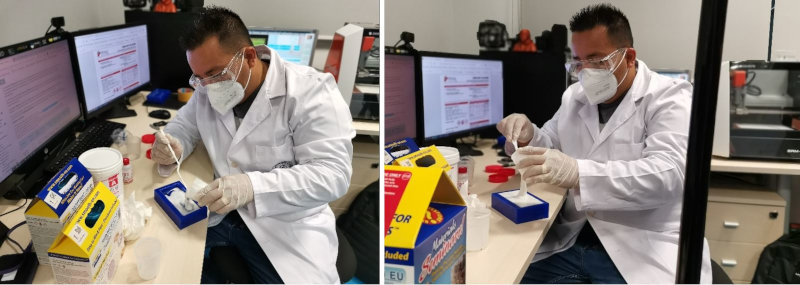
- Set aside 100 parts of the base (Part A) and add 2 parts of catalyst (Part B), mix both parts VERY well until a homogeneous mixture is achieved.
- Pour the silicone wash into the box or apply with a brush if it has been previously thixotroped.
- NOTE: Normally, low hardness silicone is used for casting molds, as it allows a better demoulding and thus does not damage the original.
Silicone page for the mold Low Cost Silicone Base + Catalyst.
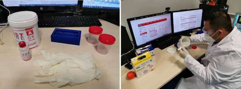
I have used a Machine of horizontal movement of the Technological Instrumentation Service (SIT) to eliminate the bubbles that are created in the silicone. Although the movement of the worktable can be adjusted, it did not help to eliminate bubbles. I also used an ultrasound equipment that they use in the laboratory to eliminate bubbles of other substances, but I also do not eliminate the bubbles of the silicone, I think it is too viscous.
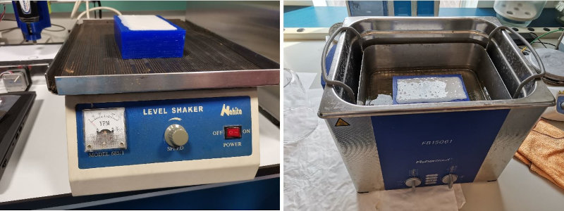
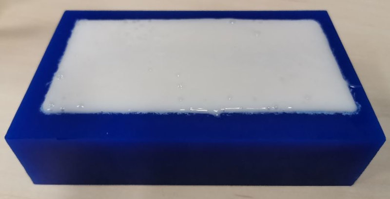
One method of removing bubbles is to vibrate or bump the wax mold against a table. Wait 15 hours for the silicone to solidify and remove the mold.
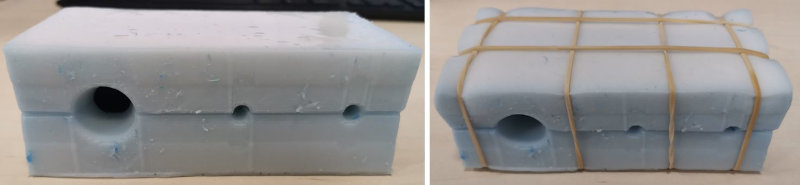
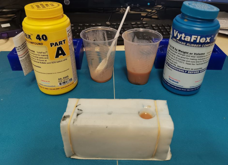
Casting material for the handlebar grip (VytaFlex 40 Urethane Rubber Compound)
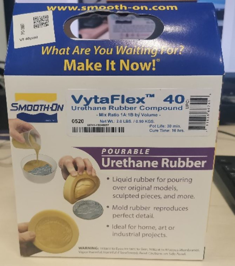
IMPORTANT: Premix Part B before using. After applying amounts equal parts A and B in the mixing bowl, mix well for at least 3 minutes scraping the sides and bottom of the bowl several times.
Hardening: Allow the mold to harden for at least 16/24 hours) at room temperature (73 ° F / 23 ° C) before removing from the mold.
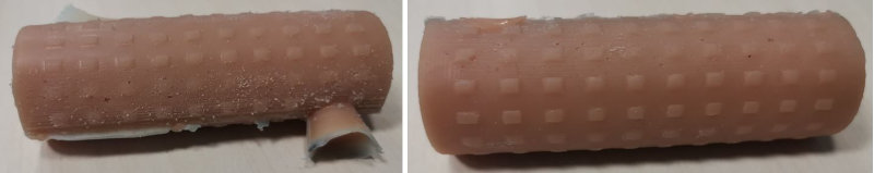
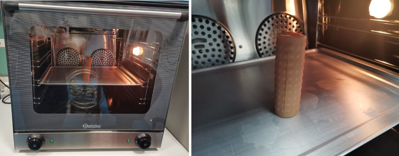
Extra Harden: Optional ... After allowing to harden overnight, heating the rubber to 150 ° F (65 ° C) for 4-8 hours will improve its physical properties and its performance.
My files Handlerbar
Files Fusion360
handlebar Project Fusion360 (.f3d)
Files ".STL"
Files Aspire ".crv3d"
Files UCCNC ".txt"
roughing Lower Counter Mold (.txt)
finishing Lower Counter Mold (.txt)
roughing Upper Counter Mold (.txt)
finishing Upper Counter Mold (.txt)
INTERFACE AND APLICATION PROGRAMMING
Final project interface with Unity
This week I have made an interface in Unity for my final Project. I have created a virtual scene where the movement of the platform (pitch) is simulated, depending on the angle of inclination, the linear actuator will be activated until reaching the real angle of the platform obtained with an MPU6050 inclination sensor. When the virtual angle and real angle are equal, the desired angle will be reached and the actuator will stop.
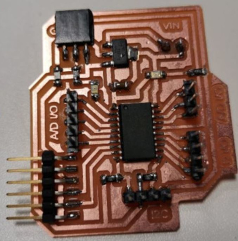
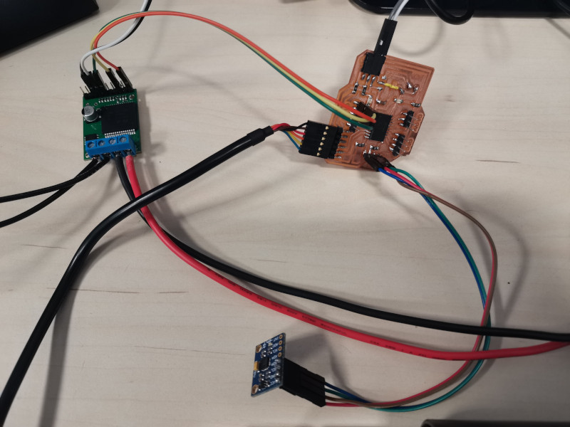
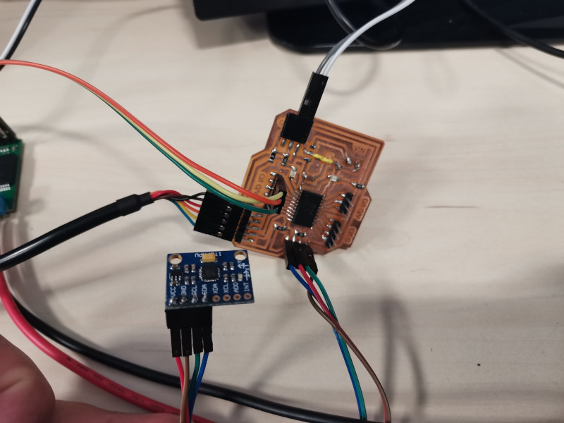
I have used my boardATtiny3216 that I built in week 13 "Networking and communications".
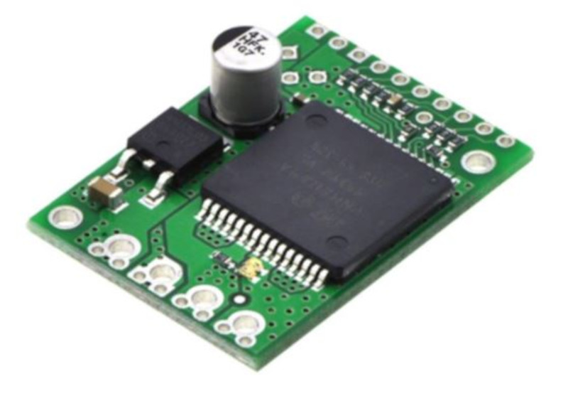
To control the motor use the pololu shield (VNH5019) from week 12 "Output Devices".
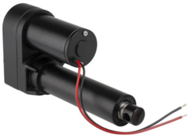
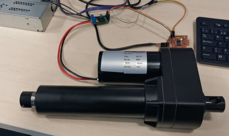
The actuator I'm going to use is the RS Electric Linear Actuator from week 12 "Output Devices".
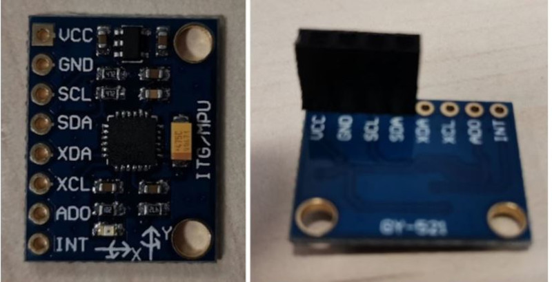
To measure the real angle of inclination use the MPU6050 sensor from week 10 "Input Devices" .
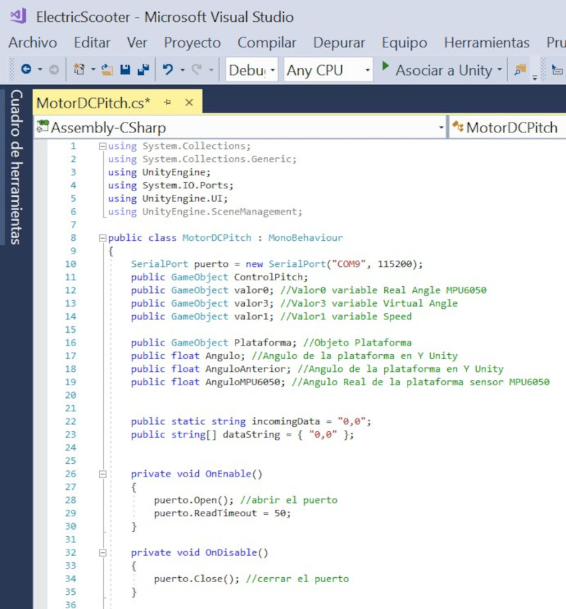
Communication between Unity and the board is done through the USB port. I use the Arduino IDE to program the ATtiny3216 board and to test communication with the computer's serial port.
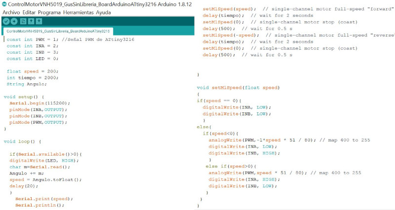
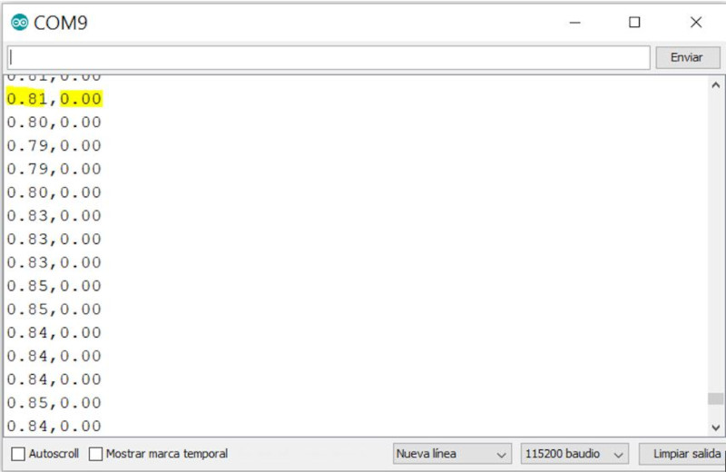
I create an Arduino program to send the motor speed data from the ATtiny3216 board to Unity only to display the speed value on the interface.
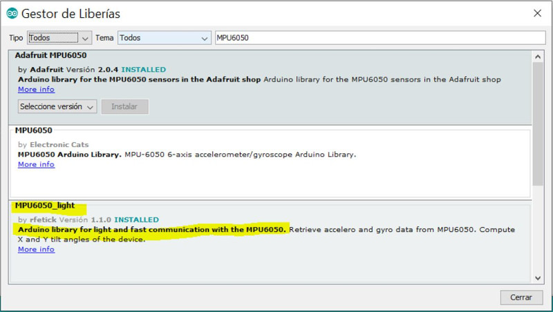
I have tried MPU6050 libraries but they only work with Arduino ATmega microcontrollers and for ATtiny microcontrollers I found the following MPU6050_light library.
Open Arduino IDE - Library Manager and put MPU6050 in the browser. Download the MPU_light Library.
I open the example to test that the MPU6050 works with the ATtiny3216.
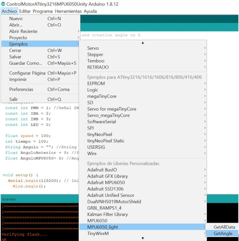
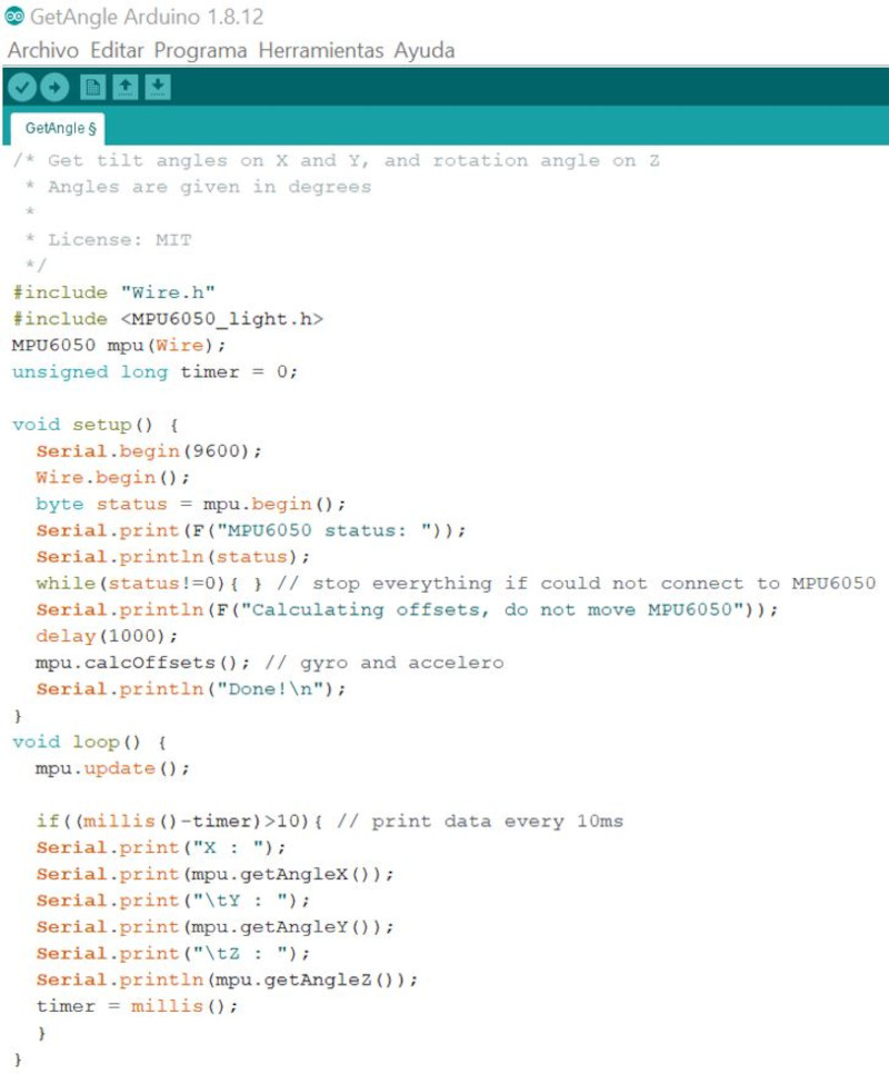
I link the GetAngle example with the motor control program I have, I will only need the angle in Y.
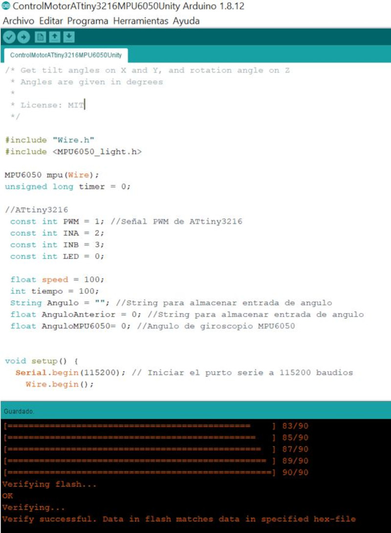
I compile the program and open the serial port to see the two angle data of the MPU6050 and the speed of the motor.
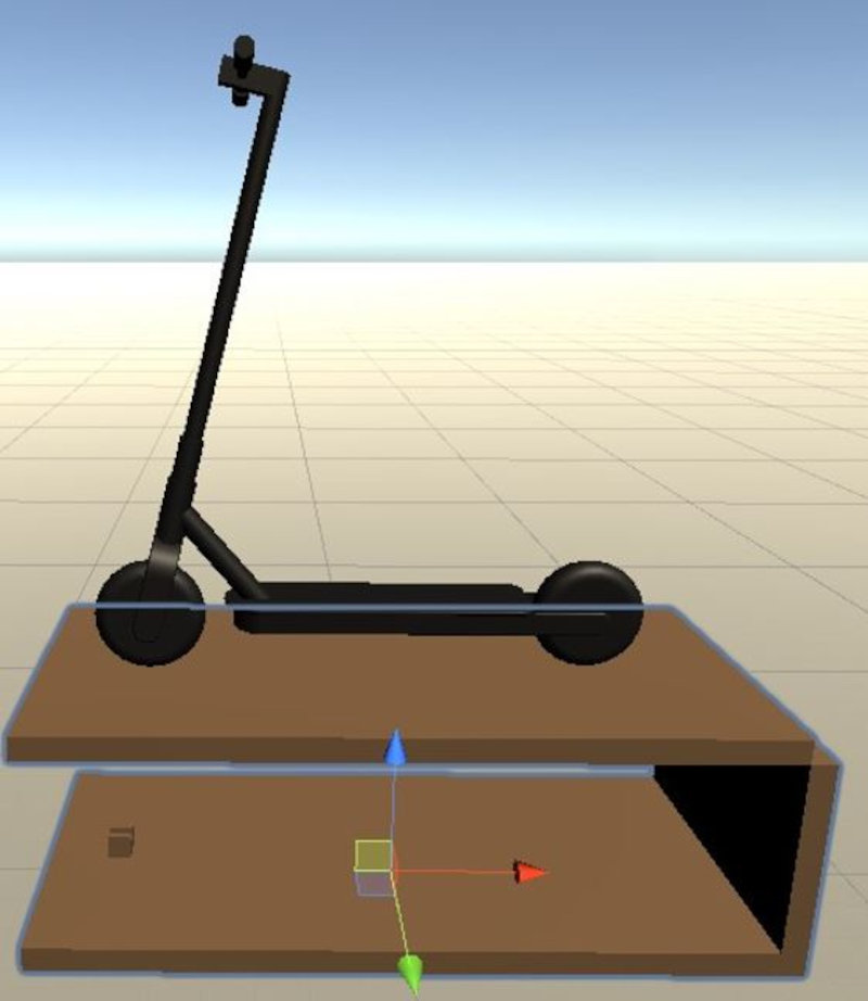
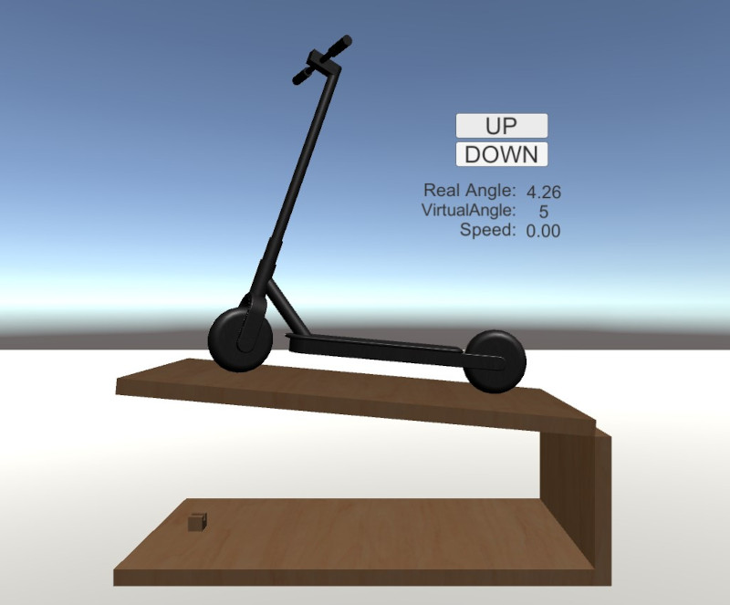
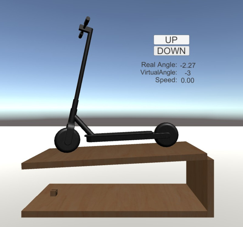
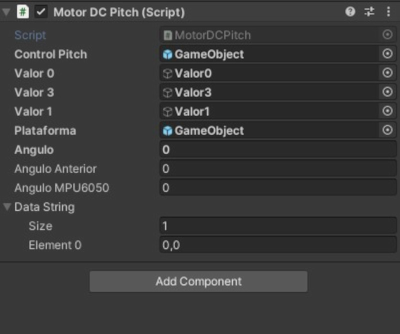
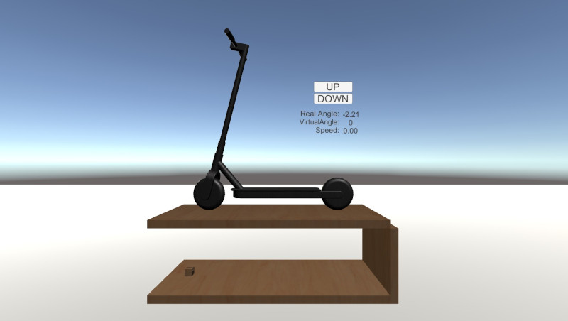
I create a scene in Unity to control the movement of the platform. With an Up button I go up one degree each time I click, and with the Button_Down I go down one degree. In addition, the real angle of the MPU6050, the virtual angle of the platform in Unity and the motor speed are displayed. Each time you click on the buttons, the platform will move, modifying the angle of inclination in the Y axis. In addition, the motor will be activated by moving the rod until the angle value of the mpu6050 reaches the virtual value of the Unity platform.
In week 2 Computer-Aided Design I designed the models of the platform and the electric scooter. Also create a project in Unity to make the animations the movement of the two objects. I'll use this project to get started with the interface. (Unity Files / ElectricScooer (Unity Project).

First I create a basic interface in Unity where the actuator drive speed value is displayed.
Now I am going to create the interface with buttons and the MPU6050 Real Angle, Virtual Angle and Velocity variables.
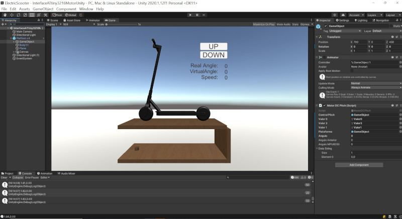
I made a script to program the communication between Unity and Arduino and get the Angles and speed values. In addition, the variables and their operation are programmed within the logic of the program.
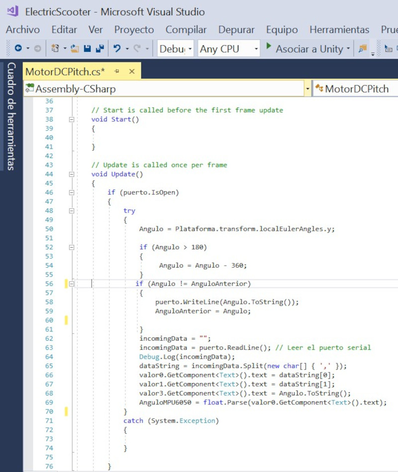
First I am going to perform the movement of the platform manually. I change the values of gameobject in its transform (rotation Y). By varying these values, the platform model goes up and down. In addition, the tilt value is sent to the ATtiny3216 board to drive the motor.
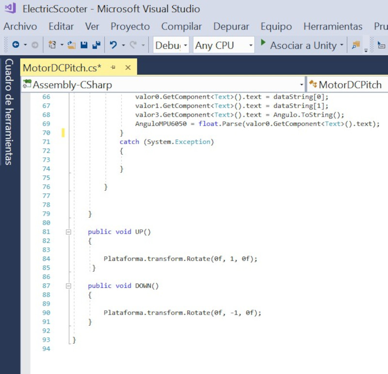
Now the actuation is carried out by means of the "UP" and "Down" buttons. When any of these buttons is pressed, the platform model in its "rotation Y" transform is increased or decreased by 1 degree.
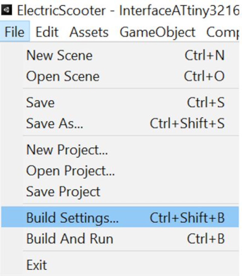
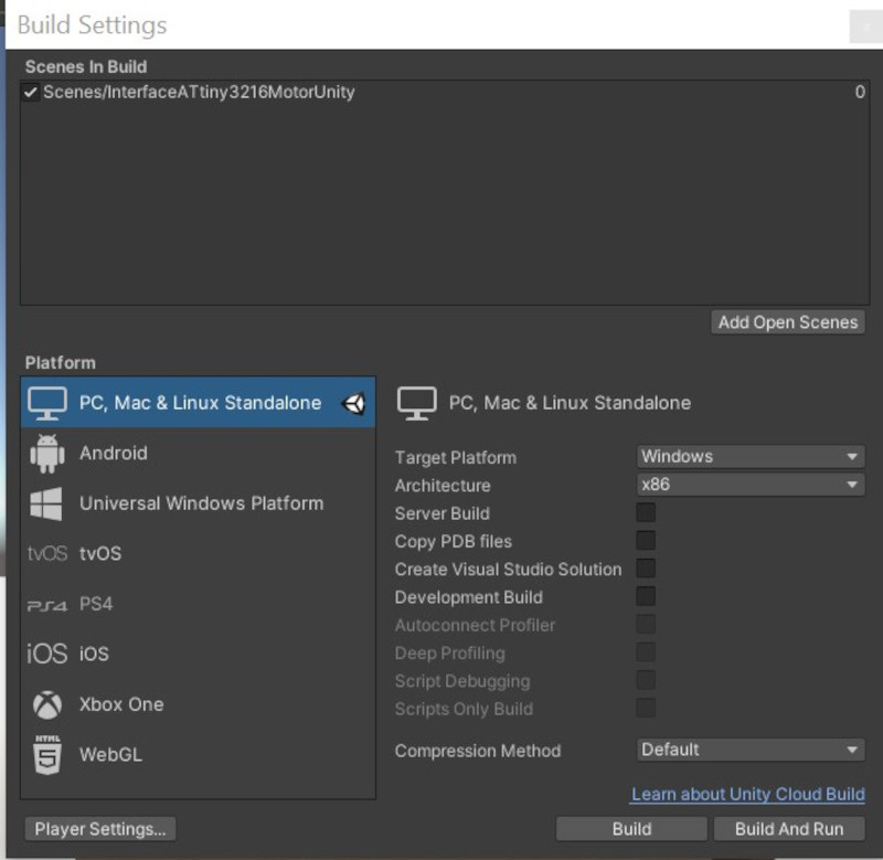
To create the .exe file (executable). Click on File / Build Settings ...
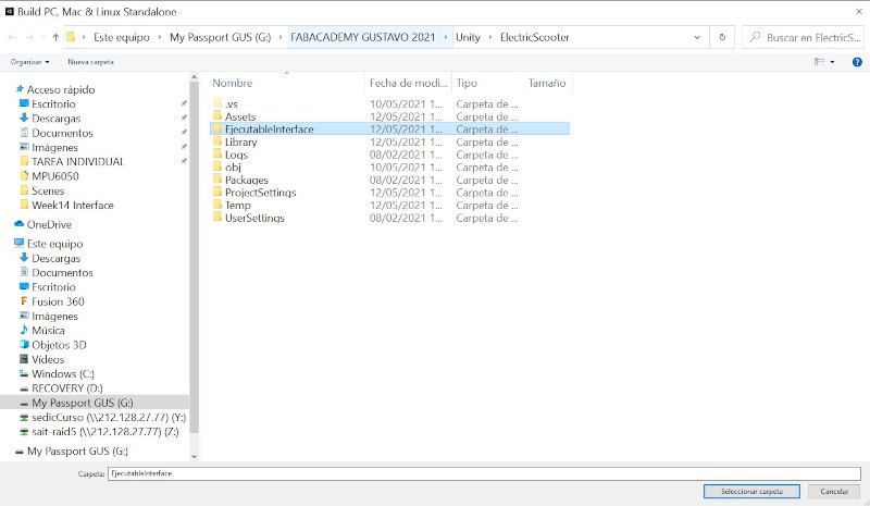
Create a folder where the .exe file will be saved.
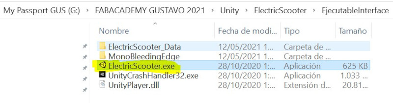
Open the .exe and the application will start.
My files "Interface"
ControlMotorVNH5019_Without Library_BoardArduinoATtiny3216
ControlMotorATtiny3216MPU6050Unity
SLIDE