
WEEK 12
OUTPUT DEVICES
Group assignment: Measure the power consumption of an output devic.
Individual assignment: Add an output device to a microcontroller board you've designed, and program it to do something.
1. Group assignment
Go to the Sedicupct website
2. Individual Assignment
2.1 ELECTRIC LINEAR ACTUATOR
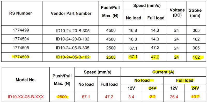
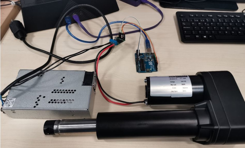
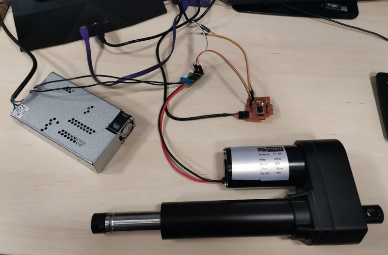
I will use an electric linear actuator for my final project, this actuator will generate the pitch motion of the electric scooter simulator platform. The actuator is a RS Pro Electric Linear Actuator ID10, 24V DC.
Link RS Electric Linear Actuator.
Datasheet RS Electric Linear Actuator.
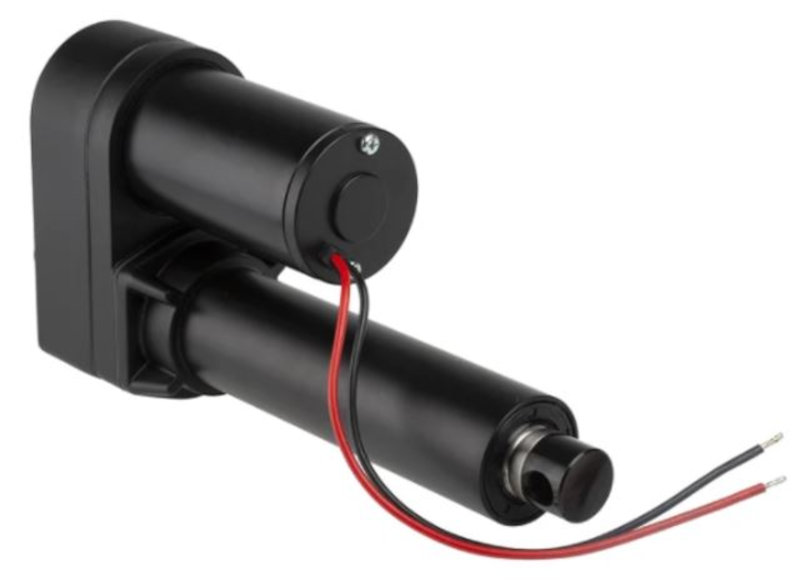
Features & Benefits:
- Input voltage 24V DC.
- Max. load:2500N (push/pull).
- Max speed: 47.2 mm/s (full load), 67.1 mm/s (no load).
- Stroke length: 102 mm.
- Black design.
- Minimal operational costs.
- Energy efficient.
- IP protection level: IP54.
2.2 MOTOR CONTROLLER BOARD DESIGN
I have seen that a DC motor controller appears on the output device website and I have thought to guide myself by Neil's hello.H-bridge.44 that uses an A4953.

I have seen assignements from students from other years who have used the same controller. For example:
Failsal-alkilani/Assignments/2020.
Benjamin-lemay/Assignments/2019.
Robert-hart/Assignments/fab.cba.mit.
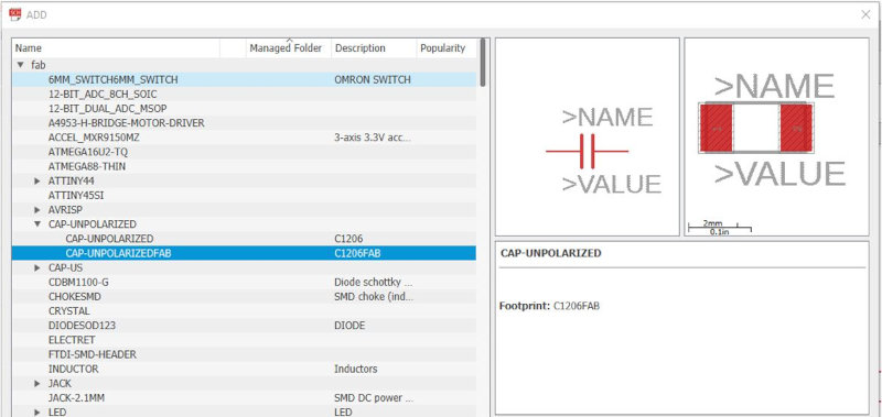
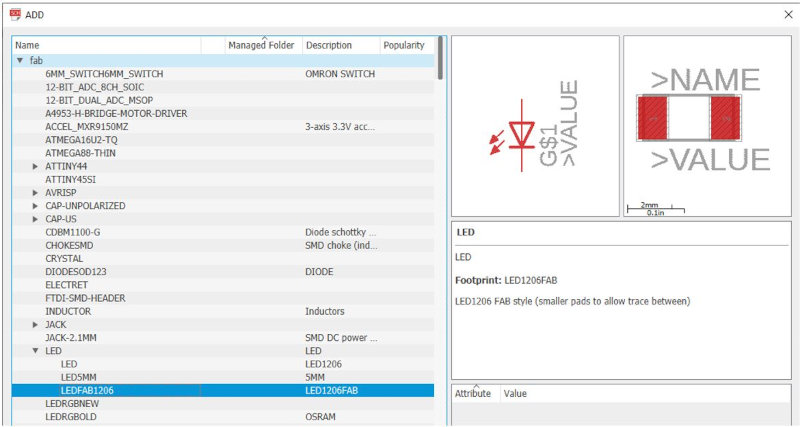
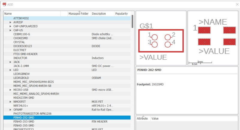
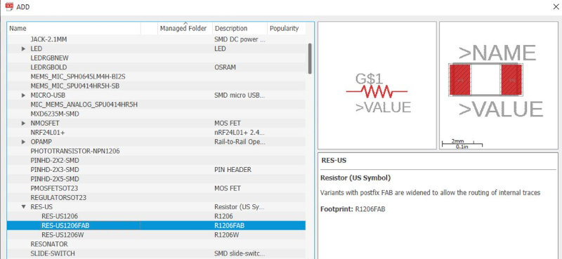
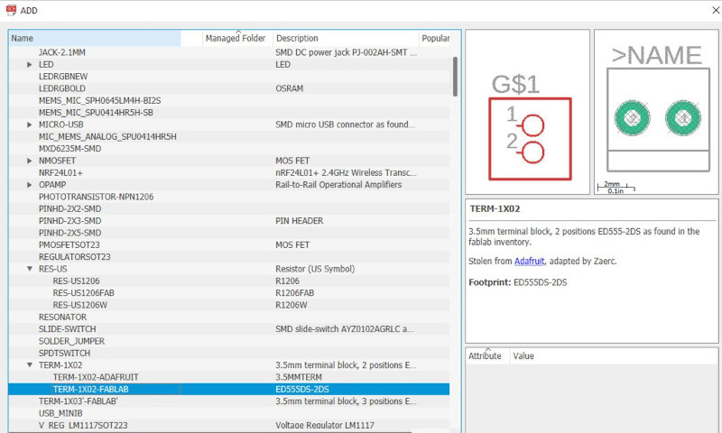
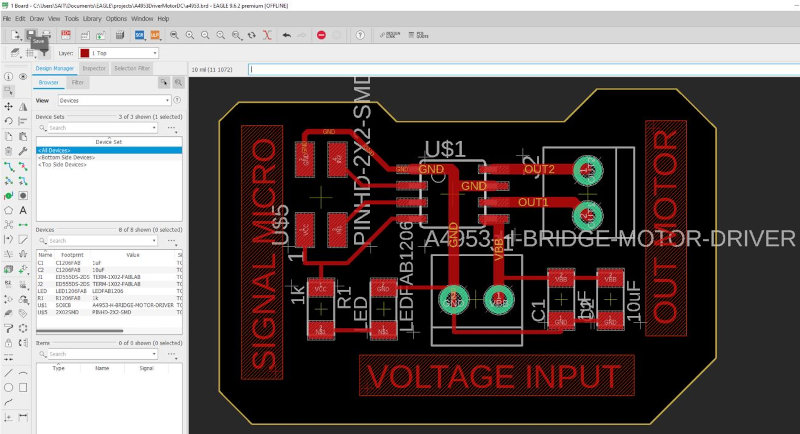
Designed the board with the Eagle program, Add component A4953-H-BRIDGE-MOTOR-DRIVER from the Fab library and the other components: capacitors, LEDs, connectors, etc.
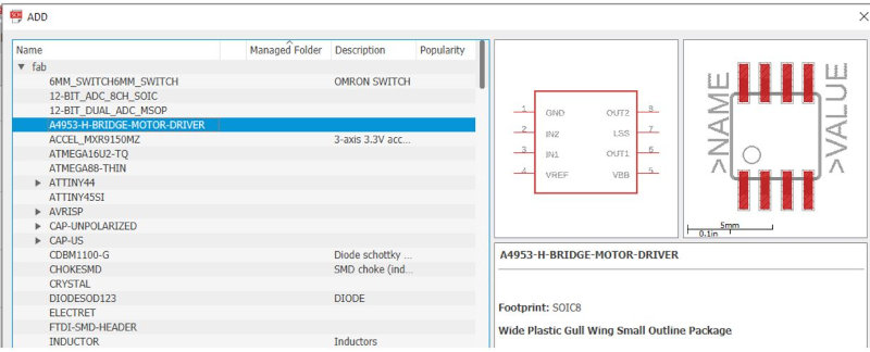
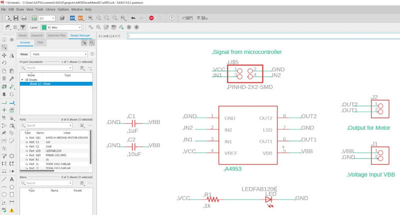
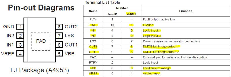
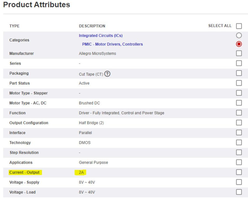
2.2.1 A4953 ELJTR-T DC electric motor controller
Designed for pulse width modulated (PWM) control of DC motors, the A4953s are capable of maximum output currents to ± 2 A and operating voltages to 40 V. The input terminals are provided for use in controlling the speed and direction of a DC motor. externally applied PWM (pulse width modulation) control signals. The A4953 controller contains an internal Hbridge, so the motor direction can be control.

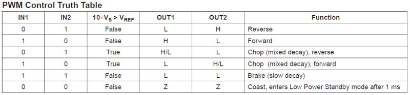
With the PWM the motor is controlled, changing the direction, braking the motor, to help us program the microcontroller the following table of the datasheet is used.
I have found a problem, the linear electric actuator has a range of 2A without load and 13A with maximum load, so the A4953 controller that has a maximum of 2A would not work for me for this actuator. On the Texas Instruments website look for DC Motor Controllers (BDC) that support at least 10Amp.

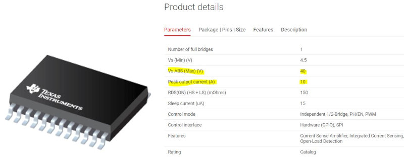
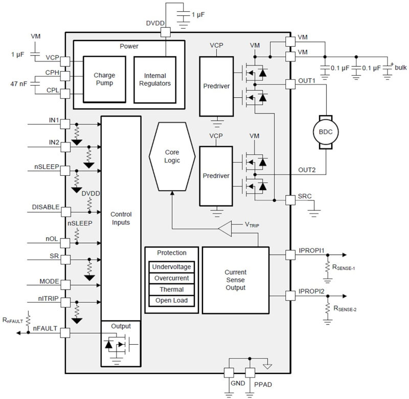
2.2.2 DRV8873 H-BRIDGE MOTOR DRIVER
Texas Instruments DRV8873 / DRV8873-Q1 H-Bridge Motor Driver is an integrated driver ic for driving brushed DC motor in automotive and industrial applications. Two logic inputs control the H-bridge controller, which consists of four N-channel MOSFETs driving bi-directionally motors with maximum current up to 10A. The device operates from a single power supply and supports a wide input source range from 4.5V to 38V. A PH / EN or PWM interface allows easy interconnection with controller circuits. Alternatively, independent half-bridge control is available to drive two solenoid loads. A current mirror allows the controller to monitor the load current. This mirror approximates the current through the high-side FETs and does not require a high-power resistor to sense the current.
This controller has a few pins and a very small design and with the equipment that I have soldering I will not be able to solder it.
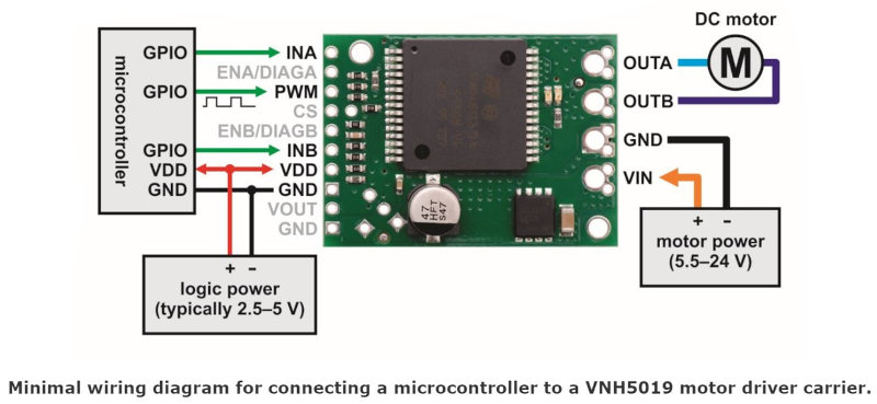
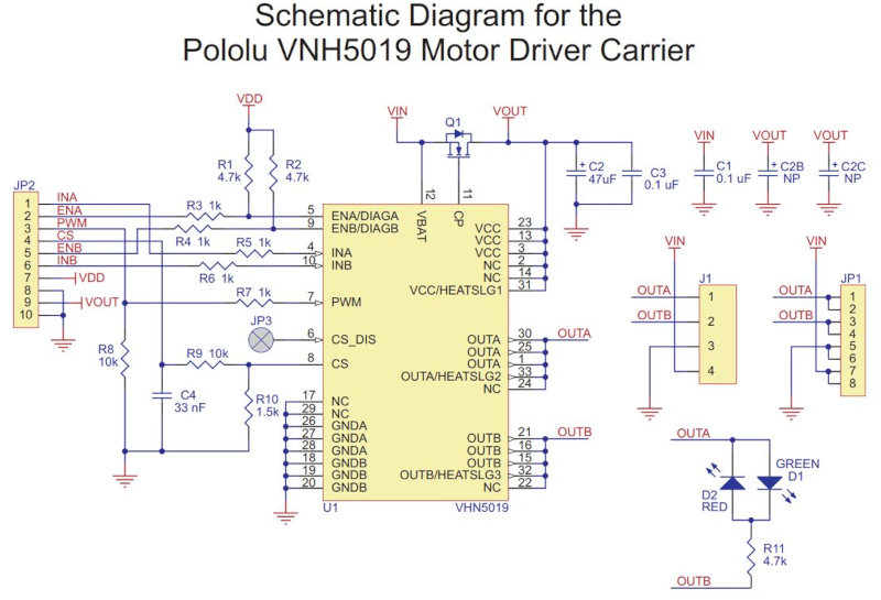
2.2.3 VNH5019 Motor Driver Carrier (Pololu)
In the end I will use a pololu module Single Motor Driver 12A, 5.5 - 24V.
Features:
- Motor Channels: 1.
- Maximum PWM frequency: 20 kHz.
- Operating voltage: 5.5 V - 24 V.
- Continuous output current per channel: 12 A.
- Motor Controller: VNH5019.
The Pololu 12A, 5.5 - 24V Single Motor Controller operates from 5.5 to 24 V and can deliver up to 12 A continuous (30 A peak maximum). It operates on logic levels from 2.5 to 5 V, supports ultrasonic PWM (up to 20 kHz), and features current sense feedback (an analog voltage proportional to motor current). Together with built-in reverse voltage, overvoltage, undervoltage, over-temperature, and overcurrent protection, these features make this product an excellent general-purpose motor controller. It includes a 47uF electrolytic power capacitor, and there is room to add additional capacitor.
link Robotshop Pololu motor controller
Datasheet Pololu motor controller

github motorshield dual VNH5019

Sebastiaan Moes from fabacademy 2016 used the same controller in his final Project.
2.2.3 Programming motor controller
To do the programming use my boardATtiny3216 that I built in week 13 "NETWORKING AND COMMUNICATIONS".
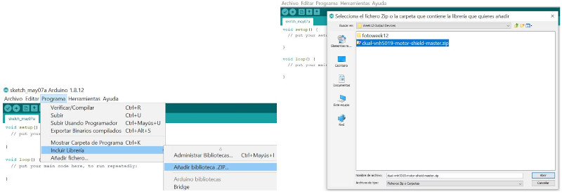
First you have to download the controller library and add it to the Arduino IDE:.
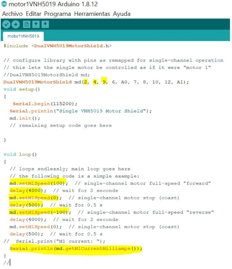
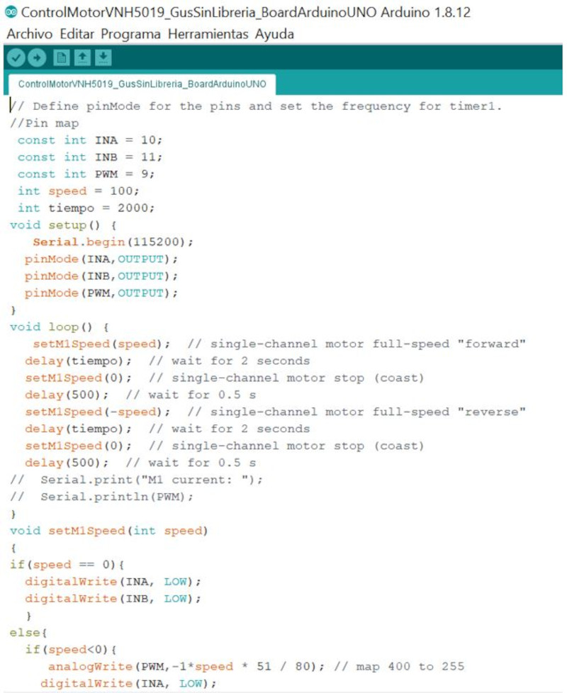
I use the following program to control the motor with the DualNVH5109MotorShield.h library using the Arduino UNO board. I modify the values of the library variables to control the configuration of the pins. The program operates the linear actuator "forward, stop, and reverse".
I create a program without using the DualNVH5109MotorShield.h library and configure the speed and time variables to control the displacement of the motor.
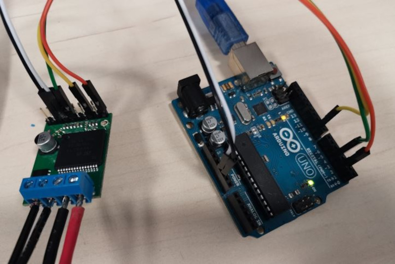
First I make the power connection: I connect the power supply to the 230v line, then I connect the power supply of the motor controller to the 24 Vdc of the power supply. I connect the motor cables to the motor controller. Now I make the control connection: I connect the Vcc / Gnd power and the PWM, INA and INB pins of the Arduino board to the motor controller. For USB communication I connect the Arduino Uno board to the computer.
Now I am going to use my ATtiny3216 board to control the motor, so I configure the INA, INB and PWM pins that I will use. Always keep in mind that the PWM is connected to a pin with a PWM signal, since at first I connected it to another digital pin without PWM and the motor did not move.
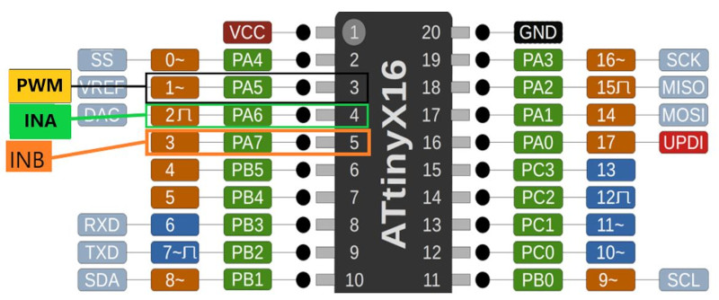
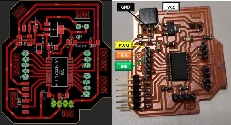

I modify the Arduino program and change the pin assignments to use it with the ATtiny3216. The PWN = 1, INA = 2 and INB = 3. Remember that pin 1 must be PWM.
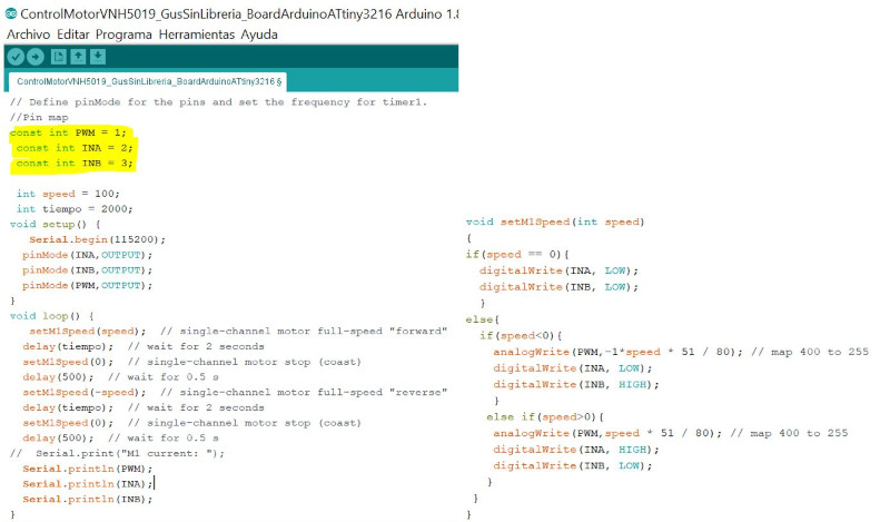
I compile the program with the ATtiny3216 parameters, keep in mind that to load the program it is done with the FTDI / UPDI connector.
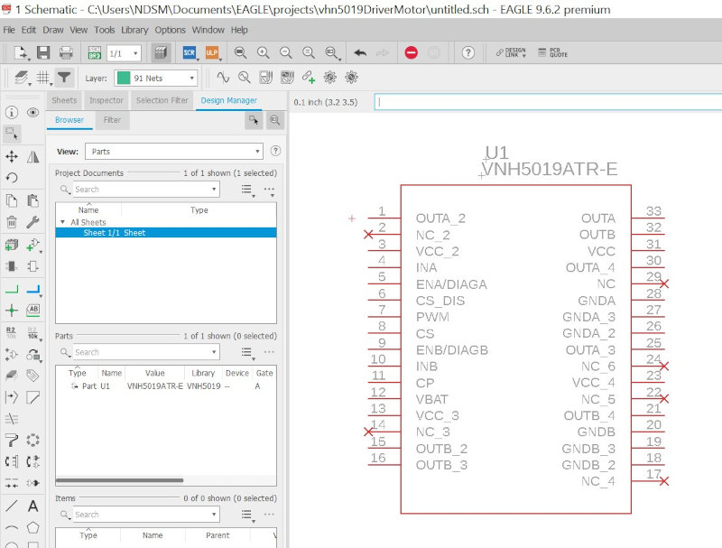
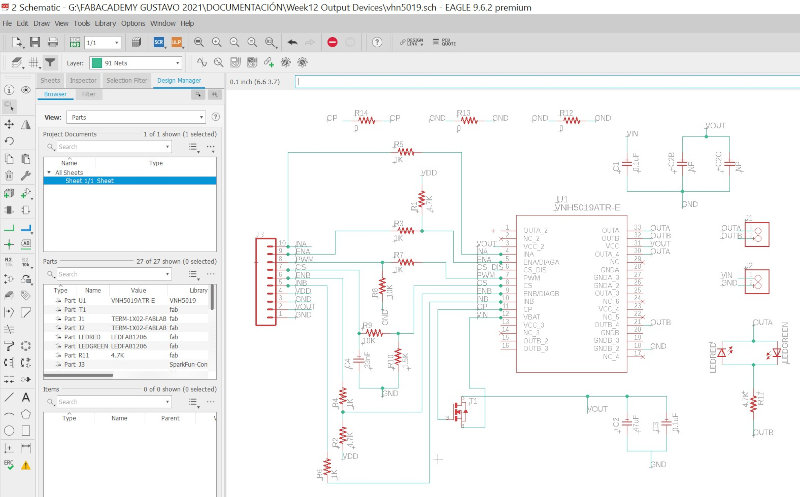
2.2.4 Design my VNH5019 board
I am going to design my own motor controller with the VNH5019 at Eagle. I download the VNH5019 Eagle library from the manufacturer's page
I follow the following tutorial to import the library in Eagle.
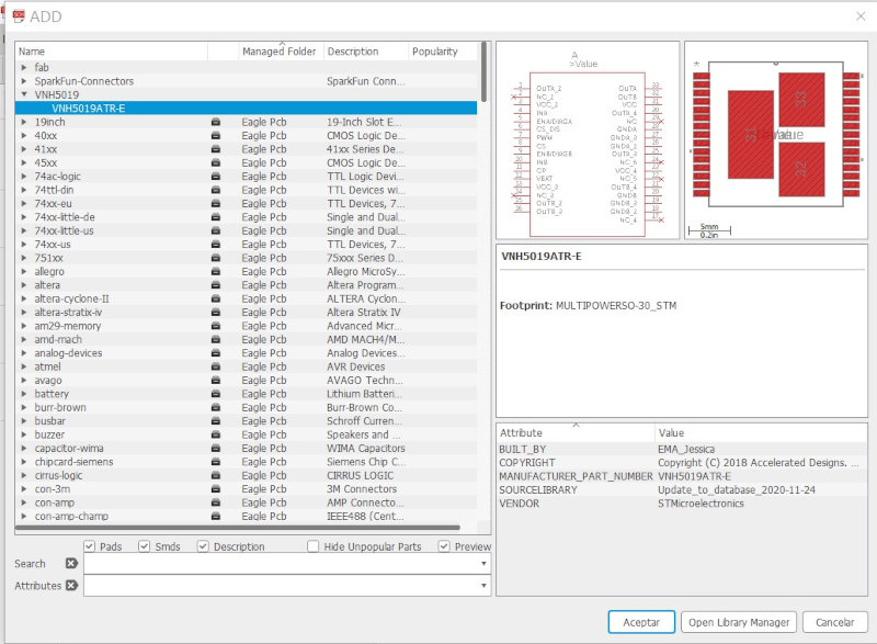
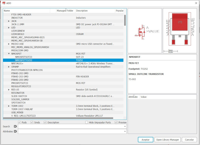
I add the electronic components in the eagle design.
4. Conclusions of the week
How was the week?
This week I have developed it with a delay, since the supplier of the electric actuator sent a wrong shipment, so I have done it two weeks later with what implies the accumulation of work each week. I am going to control the motor that I will use in my final project to control the inclination of the platform.
What went wrong ?
- I first used the A4953 motor control but its maximum value is 2 Amps and the electric actuator it used is 2 Amps no load and 10 amps on load. I have looked for information from another motor controller and found the DVR8873 but it only goes up to 10 Amps and is at the limit. In the end I found the VNH5019 motor controller which has a maximum value of 12 amps and meets the maximum values of the linear actuator.
- First I connected the PWM of the controller to a normal pin and the motor was not working so I had to connect it to a PWM pin "3".
What went well?
The best thing was to buy the shield vnh5019 pololu because it works perfect, you just have to connect the motor power cables and the INA and INB signals and the OutA, OutB, Gnd and VIN control cables. The program that comes with the Libreaia for Arduino works without problems, but I went one step further and modified the program to use it without the library.
What will you do different next time
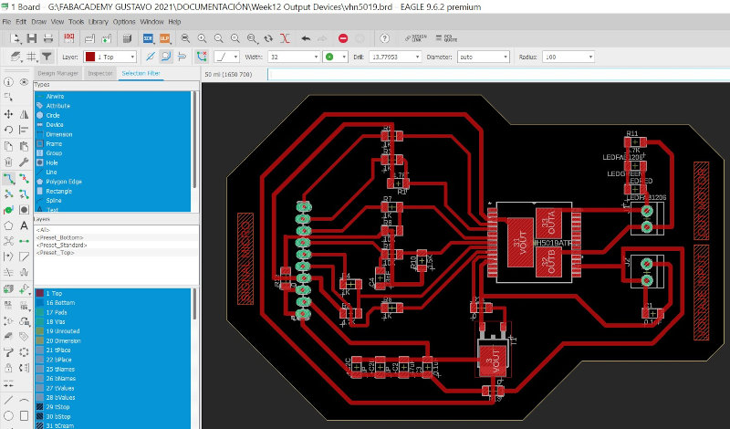
I have started with the design of my own motor control board with VNH5019, I hope this holidays I can mill and solder it to use it with the motor and see if it works the same as the pololu shield.
3. My files
Arduino Programming
Dual-vnh5019-motor-shield-master(.zip)
Motor1VNH5019 with library program arduino (.ino)
MotorVNH5019 without library program arduino and Board Arduino UNO (.ino)
MotorVNH5019 without library program arduino and Board ATtiny3216 (.ino)
Desing board motor controller Eagle
Motor controller Board Vnh5019.sch (.sch)
Motor controller Board Vnh5019.brd (.brd)