8. Embedded programming
Goals of the week:
- read a microcontroller data sheet
-
program your board to do something, with as many different programming languages and programming environments as possible.
-
Group assignment: Compare the performance and development workflows for other architectures.
Group assignment
For this group assignment we tried to use Arduino language and IDE to program an Arduino Uno Board. First we installed the Arduino IDE, then we set up the IDE. We used the COM3 Port and the Arduino Uno Board that I connect to a breadboard with two wires: one for GND and the other for VCC. I put on the bread board a led and a resistor. Then we started reading and understanding Arduino basic syntax. We run a simple blinking led code on the Arduino and everything worked.
Everybody have told me that this would be the worst week, the scary one, the one that would make you cry. Well… Maybe I’m over-dramatizing a bit… but …
The only certainty I have is that I don’t know nothing about Embedded Programming and all this has always interested me very little. But I decided I want to give it a chance, I want to try to understand the importance and the possibility around programming.
And here I am. Saturday morning, the sun is shining, the spring is spreading… and I am sitting at my desk and in front of me a 500 pages book called “Make: AVR Programming”. I have to be honest… this book is scaring me… an it’s Saturday morning, the sun is shining, the spring is… OK NO MORE EXCUSE… LET’S FACE IT!
First of all, If I want to make it interesting for me, I have the necessity to understand WHY. Why this is important? Why I need to learn it? Where this could bring me?
The author introduction give me some help to answer my first questions.
“A Microcontroller is the metaphorical glue between the real word and the virtual one. It’s part computer and part electrical component”.
OK… BUT WHY?
“Microcontrollers are at the center of an emerging culture of people building the previously impossible”
MMM…OK… BUT AGAIN… WHY?
“The goal is to get you building projects with microcontrollers and writing your own firmware in C”
MMM… OK… I MAYBE START TO UNDERSTAND WHY. BUT HERE IT COMES ANOTHER QUESTION… WHAT IS C???
We, as humans, are speaking our language. There are lots of kinds but everyone is included in a big group: NATURAL LANGUAGE, the ones that a human being can understand.
In the opposite side, there is the MACHINE LANGUAGE, a string of 0 and 1 that contains the commands executable by computer and that, of course, it’s impossible to understand for us.
Humans decided to create something capable of communicates with computers. We create new kinds of languages, a middle ground between the natural and the machine one: the PROGRAMMING LANGUAGES.
The programming languages have their code and their roles and we can divide them into two big groups:
- HIGH LEVEL –> understandable syntax similar to natural language (some example: Java, Java Script, Python etc.).
- LOW LEVEL –> language closer to machine language and therefore more complicated but faster to write (some example: C, RUST, D C++ etc.)
OK…SO BASICALLY I’M GOING TO LEARN ANOTHER LANGUAGE THIS WEEK… A CRYPTIC ONE… INTERESTING…

WELL, I HAVE TO BE HONEST, ALL THIS IS BECOMING ALMOST FASCINATING… AND THE CLOUDS ARE HIDING THE SPRING SUN… …I THINK I CAN READ OTHER PAGES…
What is a Microcontroller?
It’s a complete computer on a single (and so small and cute) chip. The core is similar to the PC one, there is a static RAM (flash) and a dinamic RAM (SRAM). You can program a microcontroller with lots of different languages. (We are using C… lucky me!) There are also lots of different kind of Microcontrollers, we are using the AVR with Harvard Architecture in which the program and the data are in different memory.
The big useful aspect of a microcontroller is that the components are all inside (built-in hardware serial interface) so what you have to do is put your byte in the right place and wait for it to get trasmitted.
THE CORE AND THE DIFFERENT PHERIPHERALS:
CPU
Central Processing Unit with a predefined logical and mathematical operations built in it. It follows your program’s operations and it executes data.
MEMORY
- Flash nonvolatile flash memory –> it doesn’t disappear when the chip loses power
- RAM volatile memory –> used to store temporary variables during calculations
- EEPROM nonvolatile memory –> slow-to-write-to, configuration settings memory that remains after power goes off.
CLOCKS
“All computers need sense of time”. Microcontrollers are provided with internal clock which runs at different megahertz for different microcontrollers
PINS
Pins have names and specific functions and they are organized into PORTS (something like 8-pins banks) that you can write to/read from. PORTS are accessible via I/O registers.
OUTPUT/INPUT
The pins can be configured as digital output and digital input. In the first case they are commanded in software to output either the supply voltage level (VCC) or the ground voltage level (GND). More easy to understand: a digital output is how a microcontroller speak to the external world. The digital input instead detect if the pin’voltage applied externally is high (more then half supply voltage –> 1) or low (less then half –> 0). To put it more simply: programs are runned by reading pins values (1 high or 0 low).
ADC/DCA
Analog to digital converters are necessary to link the microcontroller to other components that don’t speak the same language
INTERRUPT SERVICE ROUTINE
Software functions that when there is a particular conditions runs instead of the normal program you wrote. It’s called interrupted routine because the processor stops whatever it was doing in the main flow of your program and runs the appropriate function.
TIMER/COUNTER
Keep a running count of how many time a pin has changed its voltage level.
Talking about memory and space:
- the flash program memory space (the static one) is from 1KB to 32KB;
- the RAM (working memory) is 1,024 byte (not such a problem because the microcontroller process its data stream relatively quickly);
- CPU core clocks run from 1 to 20 megahertz (if, like me, you’re going to use an external crystal);
- And last but not least: all the computational and math we are going to do has to respect the value of 8 bit (1 Byte) or 16 bit. (You can integrate this values but with a speed penalty.)
DATASHEET
At this point, something was becoming clearer…more or less… so I decided to go and study my microcontroller even more closely by opening the datasheet.
I’m presenting you my new dear friend…ATTtiny44:
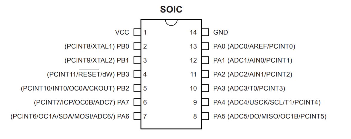
As you can see there are different pins each one with a name and for each pin there are more then one functions (see brackets). Internally they are arranged into 8pins’banks (PA/PB).
The pins configuration work thanks to the REGISTERS. We know that Atmel AVR is 8 bit microcontroller so all its ports are 8 bit wide. Every port has 3 registers associated with it each one with 8 bits. Every bit in those registers configure pins of particular port. Basically, the hardware register are special memory location and one you’ve included the io.h file in your code, you can treat the hardware registers like a normal variables. But remember, they are not, in fact inside the chip they have extra connections that let them influence the rest of the chip behaves.
These three registers are:
- DDRx register
- PORTx register
- PINx register (the x stand for each bank’s letter)
DDRx register DDRx (Data Direction Register) configures data direction of port pins. Means its setting determines whether port pins will be used for input or output. Writing 0 to a bit in DDRx makes corresponding port pin as input, while writing 1 to a bit in DDRx makes corresponding port pin as output. The default state is all zero.
EXAMPLE: + to make all pins of port A as input pins: DDRA = 0b00000000 + to make all pins of port A as output pins: DDRA = 0b11111111
PINx register PINx is used to read data from port pins. In order to read the data from port pin, first you have to change port’s data direction to input. This is done by setting bits in DDRx to zero. If port is made output, then reading PINx register will give you data that has been output on port pins.
PORTx
When DDRx is set to 1 (output), with PORTx register can set logic high or low (VCC or GND) for the pins considered, whereas if DDR set a pin like an input, with PORTx register you can activate internal pull-up that makes the input pin have fix values (=1), otherwise it would be really sensitive to oscillations and changes
In conclusion, since default status for pins is input mode, to configure output pins you have to: 1. Write in DDR those relevant pins for output mode; 2. Give them a value (high or low) with PORT register.
I tried to find this information in the datasheet too and I found a table with the explanation of register and pins organization:
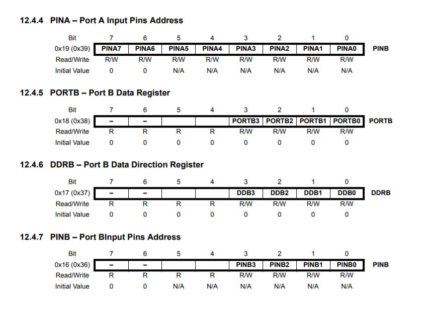
I found the datasheet really usefull to understand the function of each pin.
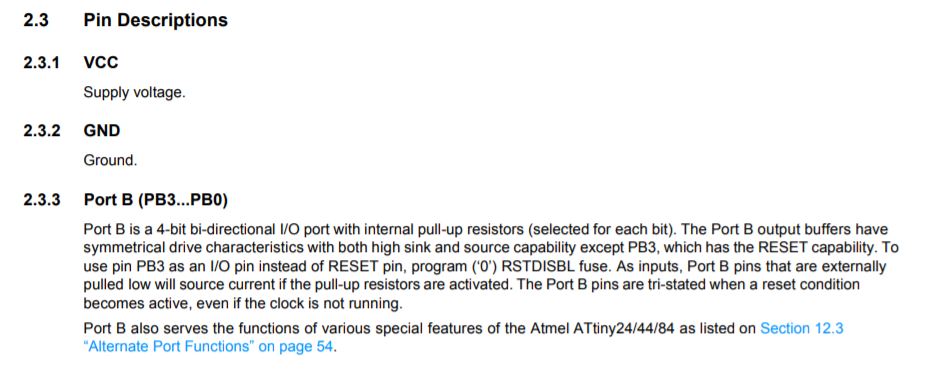
And I discovered why my microprocessor was different from my colleagues ones (they used an Attiny 45):
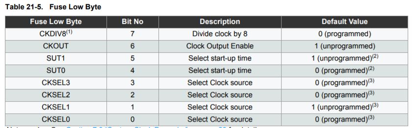
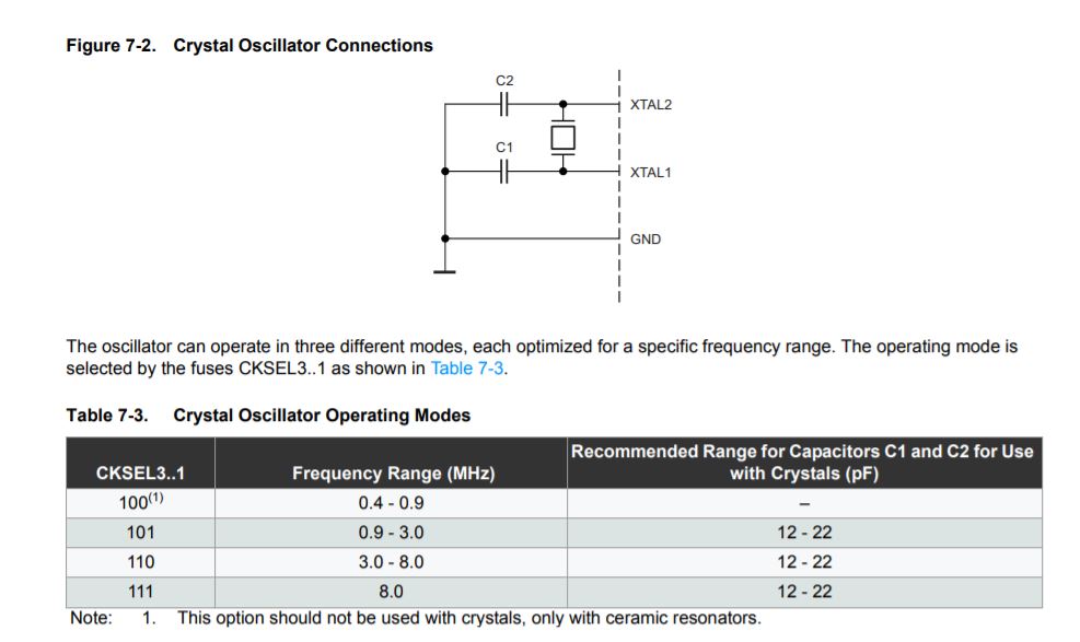
The difference is in the FUSES, specific memory registers with which the behaviour of the microcontroller can be changed. There are three types: Extended, High and Low. The type I used was Low. What I changed on my board was the CLOCK. This, by default, is set internally with a value of 8mHZ –> (0010) (CKSEL). In my case, however, the clock was set externally, replacing the crystal with a resonator and bringing it to a value of 20mHz –> (0111).
The choice of changing the clock (and hence the speed) strictly depends on the functions you want to attribute to the board.
In order to facilitate the choice of bytes to be changed in relation to the defult bytes, it is possible to use a Fuse Calculator that automatically generates the string of 0 and 1 to be assigned.
PROGRAMMING
Now that I have learned a little theory, I can finally try to understand how to send a source file on my programmee.
The steps are:
- Download the TOOLCHAIN (see week4 for more details)
- Write your own FIRMWARE in C code using a text-editor (I used Atom).
- Use a COMPILER (mine was already included in the toolchain) to convert the firmware (.c) into the machine language (.hex).
- Use a MAKEFILE, a software utility that works as a shortcut for commands.
At the end of this process you’re going to have your .hex file that you can put (“flashing”) on your board using an hardware programmer (my Fab ISP) and a software programmer (AVRDUDE).
Well… the steps’order is clear but I think I need more details about some basic concept:
-
COMPILING is turning a human-readable C code into machine language (10101011100011010010..). To compile your code you need avr-gcc, AVR specific version of GCC compiler and a makefile.
-
FLASHING means moving the code from computer to microcontroller. We can do this using AVRDUDE, a programming software to talk to and upload code onto your Atmel AVR microcontroller.
So, for the assignment of the week, I’m going to program the board I milled and solded in week 6. I used an ATTtiny 44, a microprocessor with 11 I/O pins and 16 bit timer. I added a LED connected to PA2 and a SWITCH connected to PA3.
Starting easy, my goal is to MAKE THE LED BLINKING (and maybe in the next attempt use the switch too).
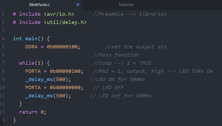
The programme I will write will have this basic scheme:
- [PREAMBLE and INCLUDE] –> to indicate the use of other sources (libraries). I’ll use
that is the microcontroller’s library and that is the one I’ll use to set the delay of my led. - [FUNCTION DEFINITIONS] –> main() –> it’s the entry point, it’s where the AVR starts executiong your code when the power first goes on
- [EVENT LOOP] –> while(1) loop, loops that continue running over and over as long as the condition inside the brackets is true. In C the 1 is always TRUE, the 0 always FALSE. So in this case the loop is going to run over and over again forever. At the end of the loop it’s necessary to insert the return(0) command, because GCC wants every main to end with a return code (otherwise the compiler raises a warning message).
First of all I have to detect the Data Direction Register (DDR) of my led pin (PA2). In my case: DDRA = 0b00000100 I could write this also like: DDRA |= (1 <<PA2)
I tried to type my C code:
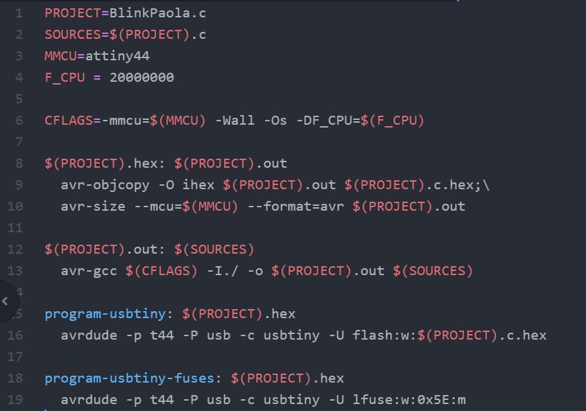
For the MAKEFILE, I downloaded Neil’s one from the schedule. I changed some lines and deleted all the commands that I didn’t need. I had to be careful with the fuses values:
program-usbtiny-fuses: $(PROJECT).hex avrdude -p t44 -P usb -c usbtiny -U lfuse:w:0x5E:m
As I explained before, I used an external clock in my board to reach 20 MHz and for that reason I inserted a resonator. The flags in this lines communicate different information about the board: + -p –> type of AVR chip –> t44 + -P –> which serial port the programmer is connected to –> USB + -c –> type of flash programmer –> usbtiny + -U –> command that reads or writes memory –> -memtype: lfuse (flash: static); -op: w (operation: write); 0x5E (byte value expressed in hexadecimal to not waste space –> see the image below for further details); :m immediate mode.
For the hexadecimal values I used the specific table in the datasheet:
At the end, this was my Makefile:
To send my program on the board at this point I opened GIT Bash, I went inside the folder I created before, and I typed make to create the hex and out file. With this command the program converts my program into the hex code.
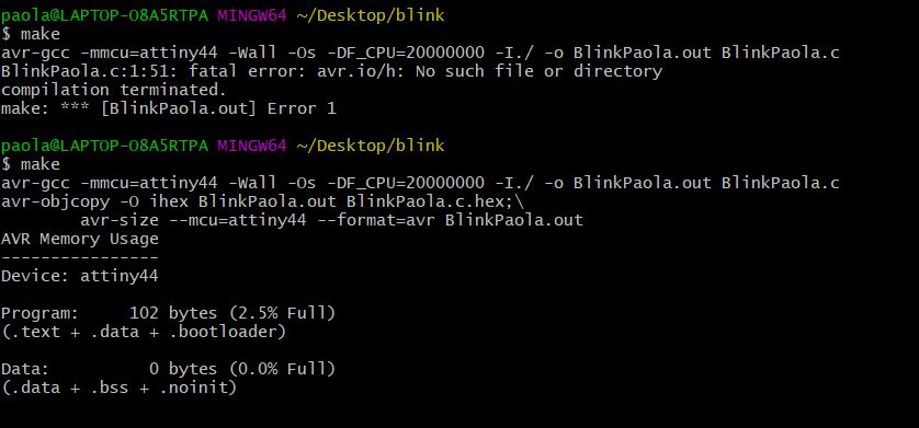
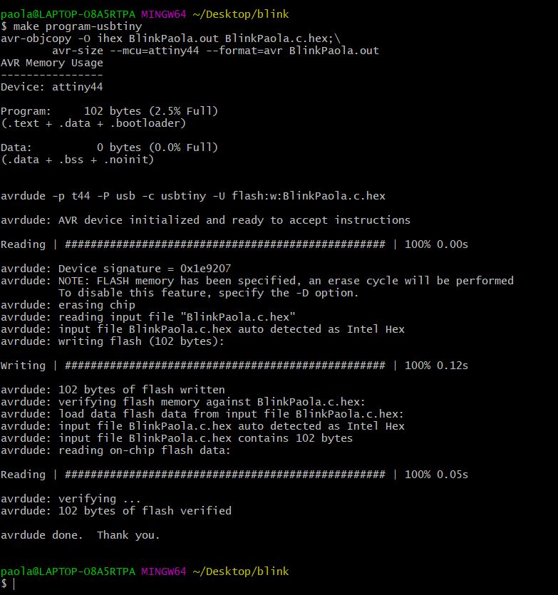
After that I used the command make program-usbtiny to flash the hex file into my board.
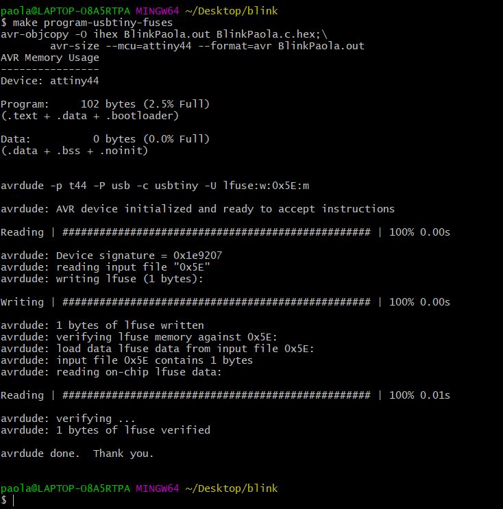
Last command to program the fuses (my external clock): make program-usbtiny-fuses
And finally, after a weekend spent trying to untangle the jungle of information, code strings and bits, I managed to get my LED to blink.
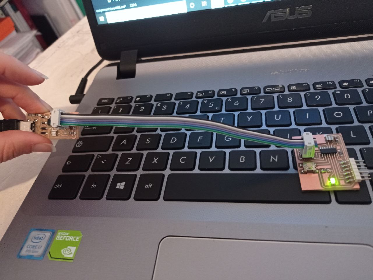
Small step for the humanity, HUGE step for me.

And this time, too, everyone lived happily ever after.