3. Computer controlled cutting
Goals of the week :
- Use the Vynil cutter machine
- Design and make a parametric press-fit kit
Vynil cutter
For the first assignment we learn how to use the Vynilcutter machine. In the Lab we have a Roland CAMM-1 GX-24
The process is:
- Download an image
- Use Inkscape or Illustrator or other 2D software to transform the normal image in a vectorial one. Work on the picture if you need to make some adjustments.
- Save the image as a .png
- Import the png in Roland’s software, Cut Studio
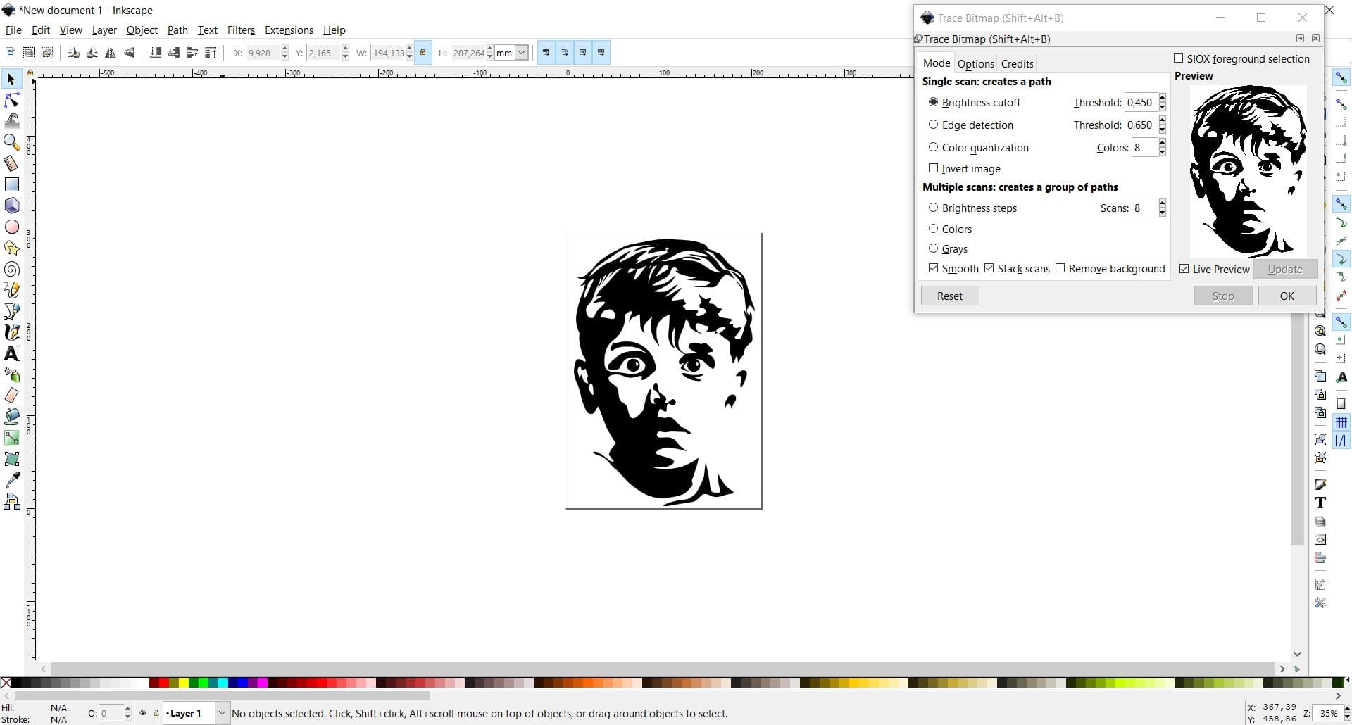
I downloaded a picture from Google and I used Inkscape to make a vectorial copy (Path –> Trace Bitmap) and I resized the image (18x25 more or less)
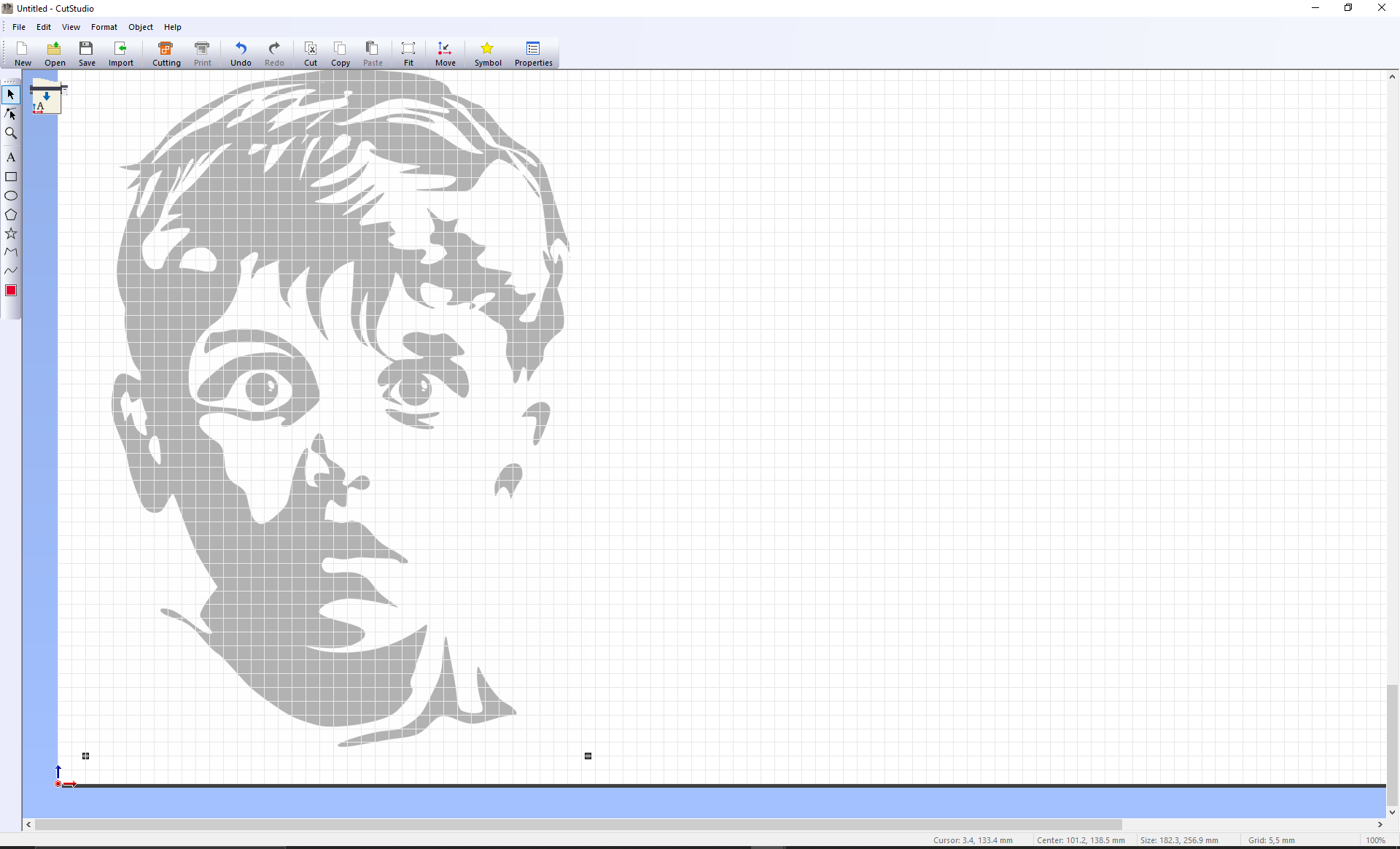
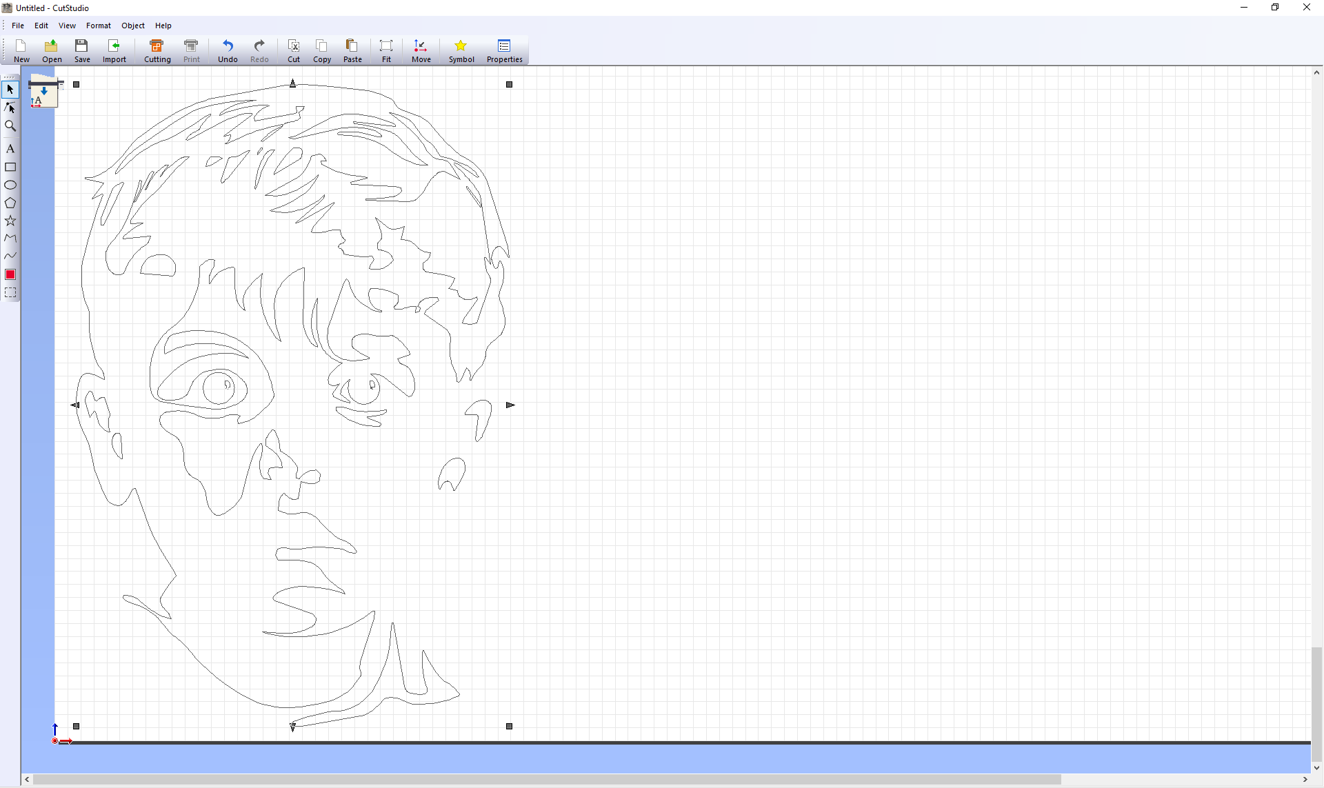
After that operation, I import the image on Cut studio. I positioned it in the left corner of the page, I right clicked with mouse on it and selected Image Outline–> Extraxt Contour Lines. A new mono-color image appeared on my original one, which I deleted.
Then I prepared the vinyl on the plotter. I followed the operation below:
- pushed the lever
- loaded the vynil sheet under the two wheels
- pulled the lever
- select the piece voice under the command select sheet
- push the origin button
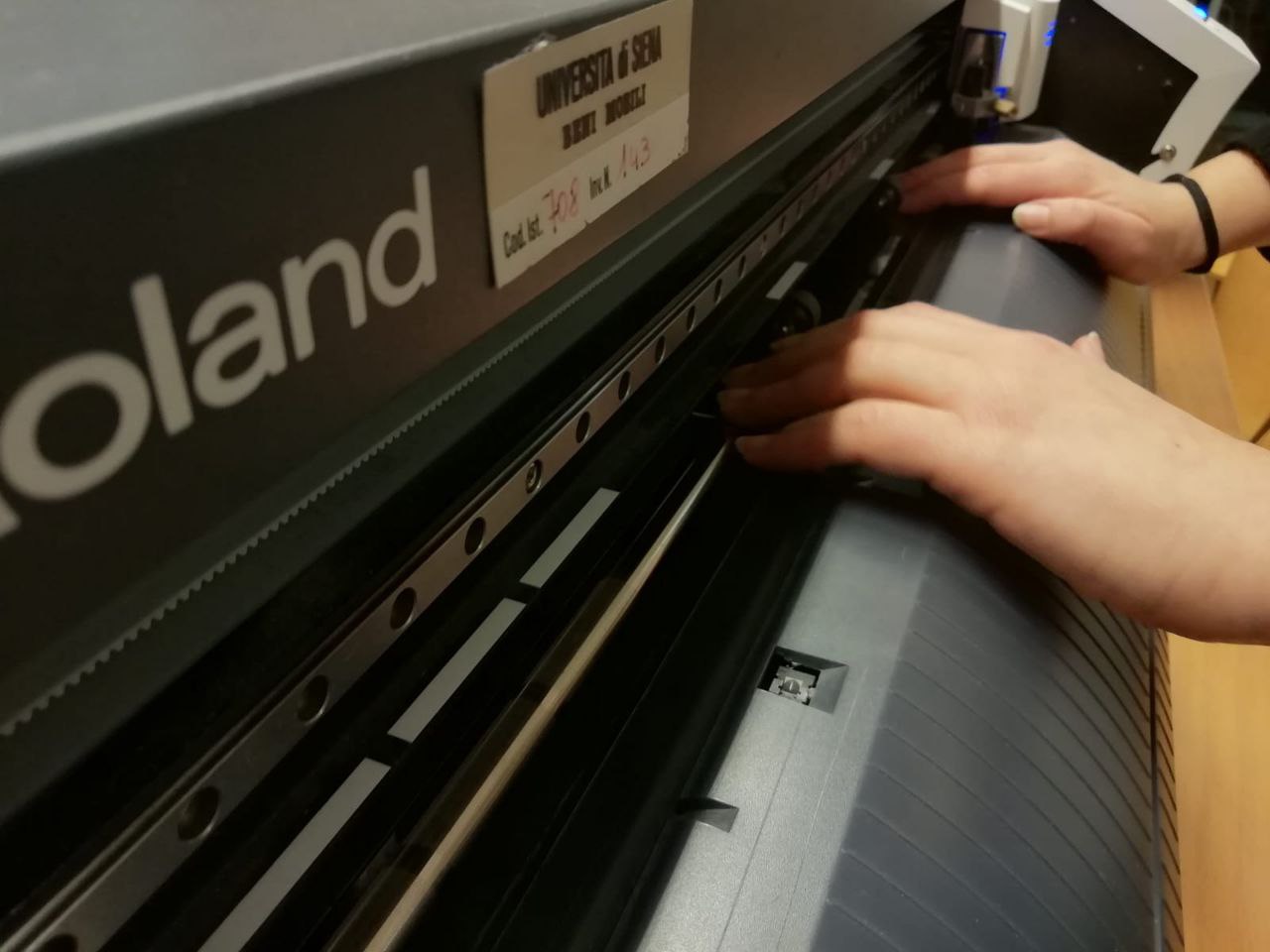
The machine was ready so I clicked on Cutting and chose machine setting
I was really exciting about the result, everything worked good in my first attempt, almost unbelievable!
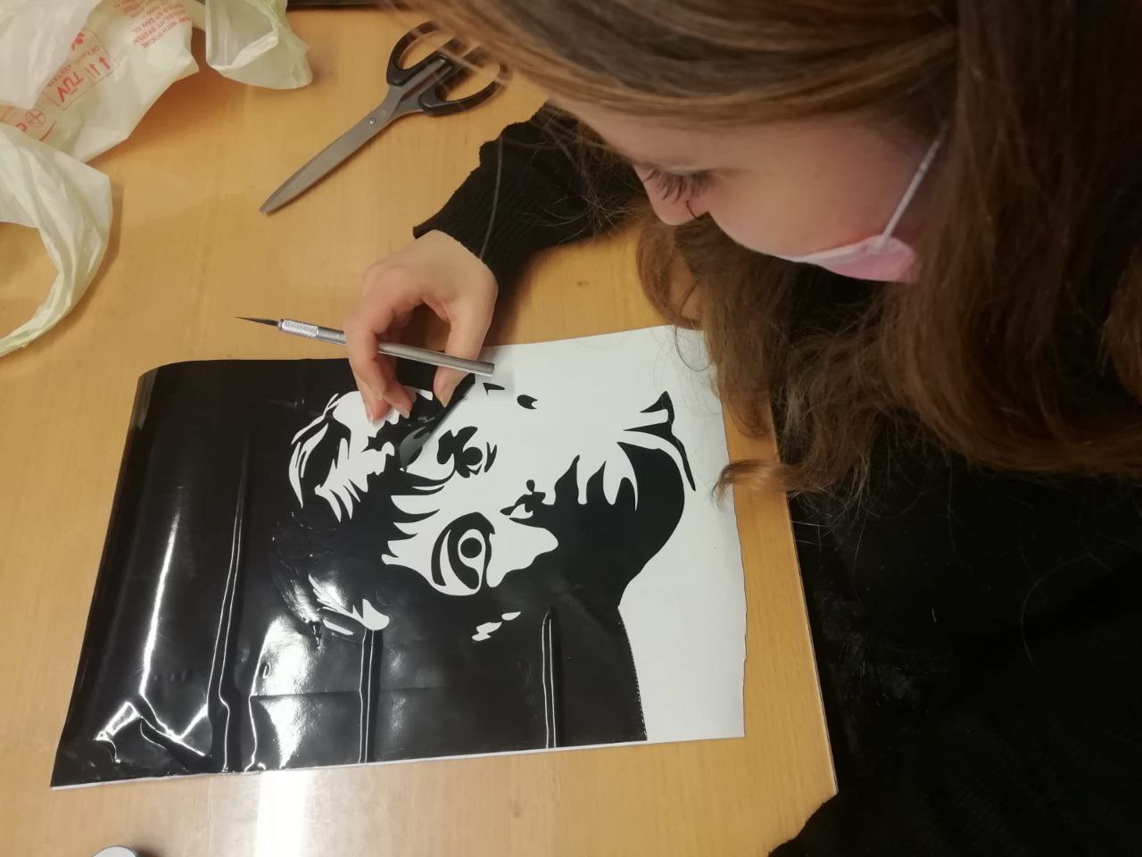
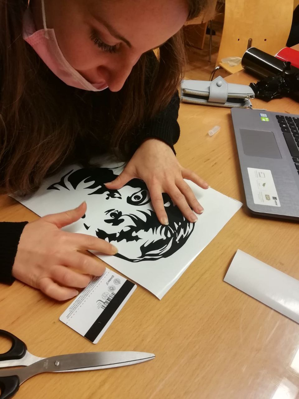
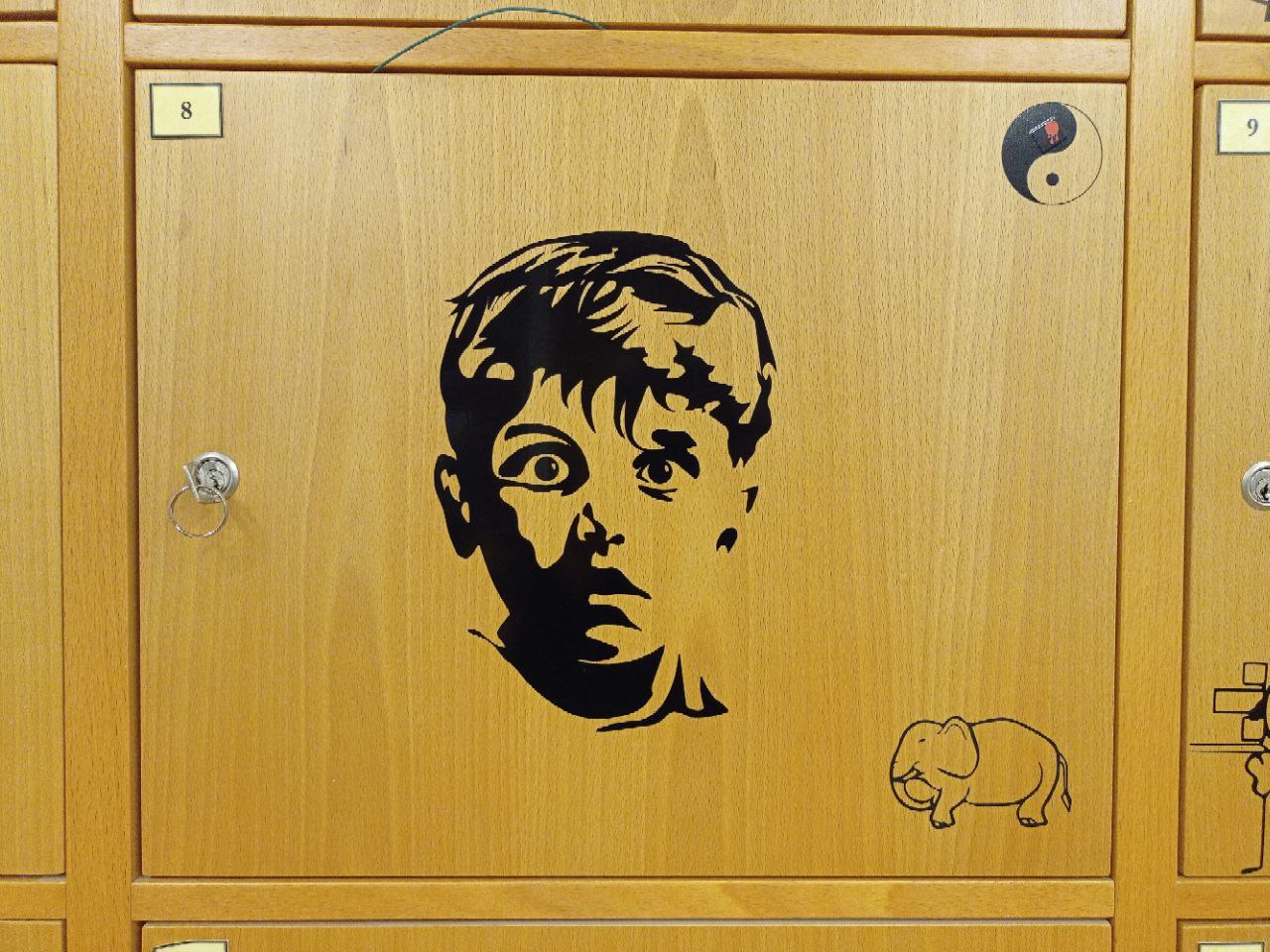
At this point the work of the machine was finished… and mine began! I removed carefully the external part of the drawing with a sharp tool. After that I put the transfer on the vinyl and let them stick together (I used a card to make the job easier). I removed the support paper and I placed my sticker on my cabinet door.
Press-fit Kit
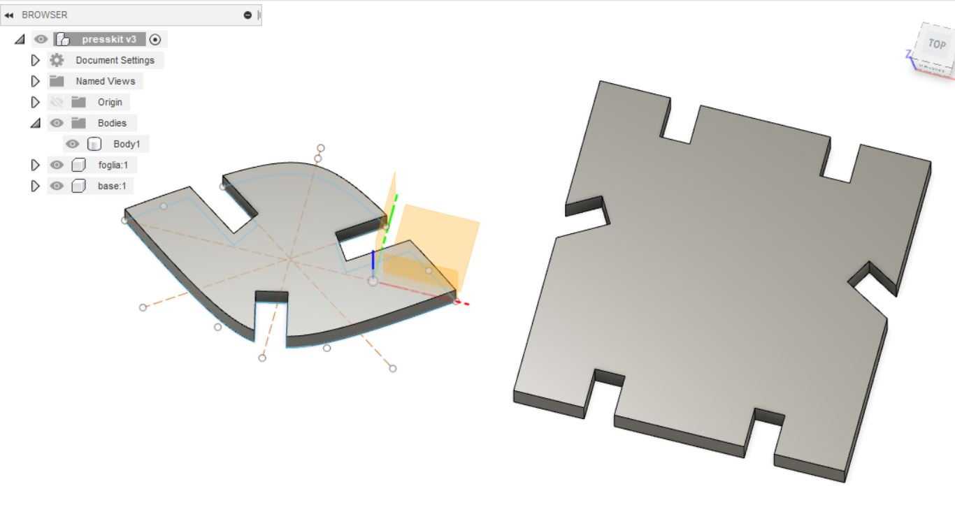
The hardest part of the week was definitely building the press-fit kit. First of all, the key part is trying to imagine it mentally. To help me, I drew a small sketch (as confusing as the chaos in my head) and from the drawing I moved on to modeling on fusion trying to make a few simple pieces.
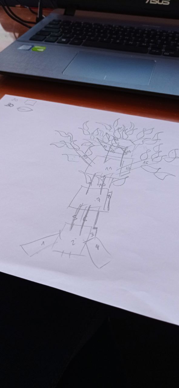
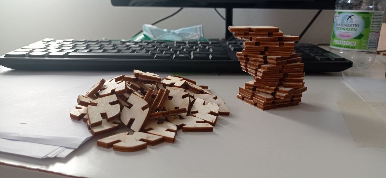
In the end it turned out that to get my tree I needed only two pieces: 1. a square for the trunk and branches 2. some leaves to thicken the crown of the tree
By processing the model on fusion I obtained two pieces of the puzzle, using parametric measurements:
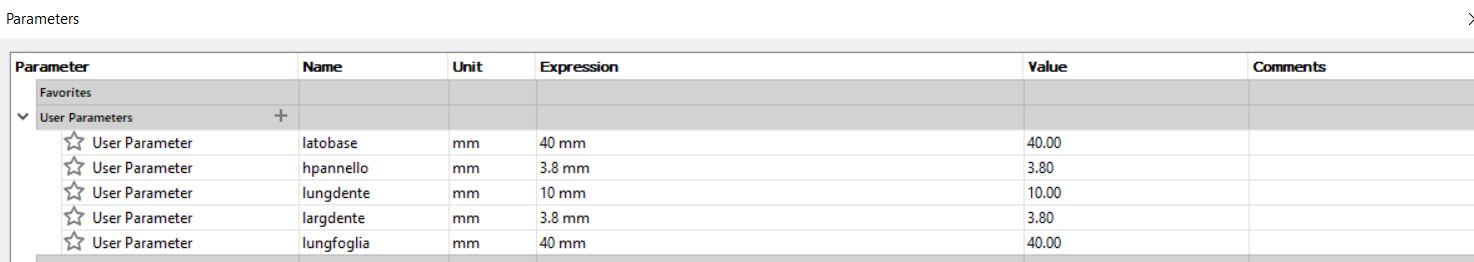
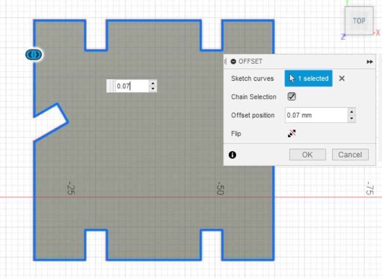
The most important thing to take into account when using the laser cutter (as we have also seen in group work) is to take into account the kerf. After having then calculated the value (0.14) it is necessary that this is applied to the model. You have several possibilities to add this value to the drawing: insert the kerf inside the parameters and then count it in the measurements or insert it through the Offset then going to modify the perimeter of the sketch and adding the value of kerf divided by 2.
The steps to follow are basically:
- select the model on which to apply the kerf.
- execute a new sketch
- select the perimeter
- add the value of kerf/2
- export the created sketch as DXF
At this point, I imported the DXF files in Illustrator, going to delete the inner perimeter of the figure and copying and pasting the two figures several times in order to get different pieces for my puzzle. I then set the outer border to red and the line thickness to 0.001. I then started printing and in a few minutes the machine lasered several components.
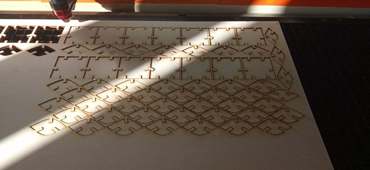
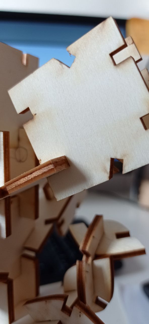
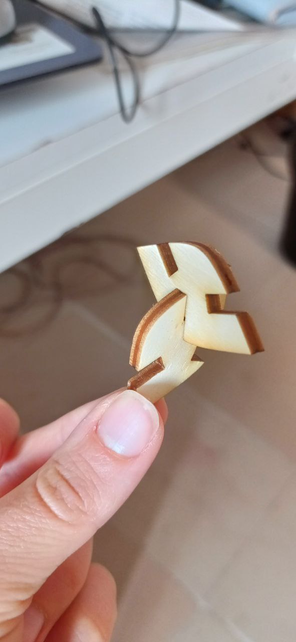
Fortunately, the joints were exact at the first shot fitting perfectly:
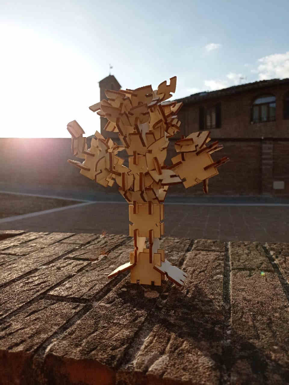
I then continued to assemble my tree and TADAAAAN this is the result:
You can download the presskit model file HERE