14. Output devices⚓︎
The course is starting to feel more and more like a final sprint, as the instructors let us know, and so we have to plan ourselves in order not to waste every assignment and focus it on our final project. All the work we can get for that goal will be a better result of it. That’s why for this output devices week I have decided to test how to output a screen, as I will almost certainly be using one in my project. My goal is to use the display as an element to show the time selection data that the user selects for a cycle of the timer. Here are the Assesment Criteria related to this weeks assignment, Output Devices:
-
- Measure the power consumption of an output device.
- Document your work (in a group or individually).
-
Individual assignment
- Add an output device to a microcontroller board you’ve designed and program it to do something.
-
Learning outcomes
- Demonstrate workflows used in controlling an output device(s) with MCU board you have designed.
-
Have you?
- Linked to the group assignment page.
- Documented how you determined power consumption of an output device with your group.
- Documented what you learned from interfacing output device(s) to microcontroller and controlling the device(s).
- Described your design and fabrication process or linked to previous examples.
- Explained the programming process/es you used.
- Outlined problems and how you fixed them.
- Included original design files and code.
- Included a ‘hero shot/video’ of your board.
For the purpose of the assignment I will try both an OLED and a LCD model. Since I would only need to display text, possibly the LCD would be a good option because it’s bigger size, but I like the OLED technology and the advantages it represents. The idea is that the tests I am going to do during the week will clarify which is a more suitable option, also taking into account programming difficulty, durability and ease of use.

About each model, both technologies have their advantages and disadvantages and therefore it depends on our needs to choose between one or the other. One of the details to take into account is the higher energy consumption of LCD vs OLED panels. This article makes a more detailed analysis of each technology, including MicroLED.


Hello.t1614.output.sergio⚓︎
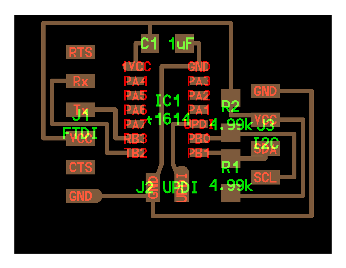
As in the Input devices week, my idea is to design a board in which I can include several connectors to be able to connect future outputs that I want to test later on. This time I have decided to make the jump to the ATtiny1614 because in the board with the ATtiny412 from two weeks ago I already used all the pins of the microcontroller and the memory was too small for some libraries, which will possibly get worse with the use of the screens.
For this board I have based the design on the hello.I2C.t1614 because it is oriented to use the I2C protocol, which is the one that Adrian has recommended me to use to connect the screens. I still don’t understand how this method of communication works but I hope to do so in the Networking and Communications week, which is where it will be explained. My intention for the board is to upgrade the UPDI connector to the 3-pin connector, add a 4-pin connector for networking and include a connector to connect some inputs to test in the feature both outputs displaying the inputs measures.


Warning
It is important to notice how the resistors for the SDA and SCL pins of the I2C connector are wired, as they are making a bridge between each pin connection and VCC.
Footprints⚓︎
To start working on the design of the board in Eagle I need the footprint of ATtiny1614 since it is the first time I am going to use it. The process of adding a footprint is detailed in Electronics Design week as adding a librarie or in Embedded Programing week since I used the ATtiny412, but this time I found another way so I will details ome images below. Component footprints come in library (.lbr) format files. This library can include one or several footprints of the same or several components. Once we have downloaded the file we just have to move it to the libraries folder that Eagle has created in Documents: PC/Documents/Eagle/libraries/. Then we should restart Eagle so that it detects the new file but there is an extra step to be done in order to be able to use it in the schematic. You can use both of this ways:
From the start menu, we drop down the Libraries tabs that appear on the left and click on the grey button of our library. This button should now turn green, which means that it has been activated for use.

In the schematic, click to add a component, and at the bottom right you will see the Open Library Manager button. A new window will open, select the Available tab at the top, look for our library and with it selected click on Use.

My colleague Lorena had some problems with this ATtiny1614 footprint two weeks ago because the ones she had downloaded had a line around them that didn’t allow traces to be drawn when routing. This problem is documented in her Input Devices week. I asked her if she could send me the modified footprint without this problem and she did, so I will attach it at the end of the documentation in case anyone wants to use it. Although you can download the original from sources like Ultralibrarian or Octopart. As you can see in the images below, the only one without a line around it is the second footprint, which is the one modified by Lorena.


Searching among different webs of libraries with Eagle components, I decided to look for a footprint for a standard 4-pin connector as well, since during the [Input Devices week] I used the 6-pin FTDI connector footprint for my input connector, having to remove the two remaining pads when editing in GIMP. Adrian showed me GCT where you can use a base component, in this case the connector, and specify the number of pins you want. The page generates several models, a 3D CAD and a link to SnapEDA to download the footprint.

Info
You have to scroll down where the 3D model is displayed and look for a tab that let’s you select the number of pads. Then, look above the list and 3D model to change tabs from 3D Model Generator to Electrical Models / PCB Footprints and choose the one with the number of pads detailed before.
Design⚓︎
As this is the first time I have used the ATtiny1614 in a board design, I have spent part of the design time reading its DataSheet. This microcontroller has 14 pins in total, so the layout is getting more and more complex. So I decided to first make a small table assigning the pins dedicated to each connector I am going to use, according to the pin layout in the picture.


| FTDI | UPDI | Input | I2C/Output | Networking | Led |
|---|---|---|---|---|---|
GND VCC TX(PB3) RX(PB2) |
VCC GND UPDI(PA0) |
GND PA3 PA2 VCC |
GND VCC SDA(PB1) SCL(PB0) |
GND VCC TX(PB3) RX(PB2) |
GND PA1 |
After assigning all the pins of each connector, 4 pins remain free: PA4 PA5 PA6 PA7. I might add them to an extra connector in case I want to use any of them later on, to have them available for use and not let them go to waste. The design process is detailed in the Electronic Design week and later iterations of other boards, so I won’t go into it here. It is summarized in adding the components to the schematic, generating the labels, transferring it to the board file, routing the connections, exporting the board as png and then editing it in GIMP to obtain a traces file and an outline file. As always, here are some screenshots of the process and the list of components used in the schematic.


| COMPONENT | LIBRARIE NAME | COMPONENT NAME | QUANTITY |
|---|---|---|---|
| Microcontroller | ATTINY1614 | MICROCHIP_ATTINY1614-SSFR_1 | 1 |
| IN/OUT connector | CONN_1x4 | BG300-04-X-X-A_REVC | 2 |
| UPDI connector | FAB | SW_SPDTSWITCH | 1 |
| FTDI connector | FAB | CONN_06_FTDI-SMD-HEADER | 2 |
| Networking connector | FAB | CONN_02x2-PINHEAD-SMD | 1 |
| Capacitor | FAB | CAP_UNPOLARIZEDFAB | 1 |
| Resistance | FAB | R1206FAB | 3 |
| Led | FAB | LEDFAB1206 | 1 |
Fabrication⚓︎
Once we have the board designed and we have generated in GIMP our traces and outline files we take the those to the Mac which we use to drive the Modela and mill the boards. This process is detailed in the Electronics Production week. As always we will use FabModules, a 1/64 milling bit for the traces and 1/32 for the outline. Below I attach some pictures of the process and screenshots with the values used for each file.


After milling the board it is important to do a post-processing to remove all the imperfections that may remain and the dirt that may have the tracks, to avoid soldering problems. Also make sure that all the tracks have been milled as in our design and that there are no unwanted joints due to any failure during the milling or with the file, as sometimes there can be clearance problems if we have not been careful in the design. We can take the opportunity to remove some of the remaining useless copper bits from the board. Again, this process and all the materials used for it are detailed in the Electronics Production week.


With the board ready, it’s time to list the necessary components and take them from the Fab’s electronics inventory. We also prepare the soldering station. In this case I made sure to take the flux, as it is the first 14 pin microchip I solder, to make it easier to solder the pins. I was a bit afraid that there would be “too many” but as I have said in other weeks, it is gratifying to see how much soldering technique I have gained after this course, so it has been quite easy.
The result has been good, although I’m afraid of how fragile the female connectors might be as they don’t sit flat on the board. Normally I take into account the length of the connectors so that they rest on the board and thus force less the soldering, but it’s the first time I used the female connectors and I didn’t take into account the full length.


Programming⚓︎
In this case, the change in programming environment and toolchain from ATtiny1614 to ATtiny412 is minimal because the process is identical in both microchips, since they share tools and library in Arduino. This process is detailed in Embedded Programming, so I only attach a screenshot of the configuration used from Arduino to send the code. To check that everything is working properly and as a debugging element, we start by uploading a basic blink to the board, which will reveal if electrically and software-wise everything is OK. In this case there has not been any problem and the LED lights up correctly.


Extra⚓︎
I think that the FTDI connector may cause some confusion, as the Input and Output connectors are labelled on the board, this one is not and the extra connector is of the same type. I’ve seen Adrian previously mark the pins with paint to distinguish them, so I asked him for help with that. He was very kind to lend me his paints, so I have taken the opportunity to do this process with all the boards I had before, so I don’t have to check the design of each board every time I want to use it, in case I have changed the orientation of any of the connectors. This way I make sure I always connect the boards in the right way, also for the networking bus which can get tricky if you dont use cable by cable connections.


LCD⚓︎
For our first output device, we are using an alphanumeric LCD display for interfacing with a microcontroller, consisting of 4 rows and 20 columns. The display has a processor capable of interpreting this code and printing it alphanumerically. The communication with Arduino is done through the LCD to I2C adapter module, which is an expander of digital inputs and outputs through serial communication. This allows you to control your LCD with just the Arduino’s I2C pins (SDA and SCL). The display contrast between the digits and the background is controlled through the potentiometer included in the module, just turn it until you get the desired contrast. The backlight is controlled by software from the Arduino, but the module allows to disconnect the backlight by simply removing the header jumper. Technical specifications:
- Input voltage: 5 V
- Input current: 125 mA
- Power: 625 mW
- I2C module base device: PCF8574
- LCD base device: HD44780
- Dimensions: 9.8 * 6 cm


I2C port⚓︎
Now that we have wired up the display through the I2C module and the corresponding connector in the board, we have to check which I2C port is the LCD using. To do so we are going to use Neil’s arduino code which is available in the communication protocols section of the networking class. You can find a copy of it written down here:
#include <Wire.h>

void setup() {
   Serial.begin(115200);
   Wire.begin();
   }

uint8_t address,count;

void loop() {
   count = 0;
   Serial.println("start scan ...");
   for (address = 1; address < 127; address++) {
      Wire.beginTransmission (address);
      if (Wire.endTransmission () == 0) {
         count += 1;
         Serial.print("   found ");
         Serial.print(address,DEC);
         Serial.print(" (0x");
         Serial.print(address,HEX);
         Serial.println (")");
         }
      }
   if (count == 0)
      Serial.println("   no devices found");
   delay(1000);
   }
Basically what this code is doing is trying the hole range of addresses for the I2C port and returning the one that has worked. It display the result through the serial monitor and keeps reading. Our I2C port for the LCD display is 0x27, but apparently it’s always this one for any LCD. This is made to create a standard for components manufacturers and facilitate the development of connected objects based on Arduino, ESP32, ESP8266, STM32 or Raspberry Pi micro-controllers. Here’s a link for the I2C addresses of the most common sensors and actuators used in electronics.


First display⚓︎
Hello World Neil’s code
#include <LiquidCrystal_PCF8574.h>
#include <Wire.h>

LiquidCrystal_PCF8574 lcd(0x27);    //set LCD address 0x27
int count = 0;

void setup() {
   //lcd.begin(16,2);           //initialize 16x2 LCD
   lcd.begin(20,4);             //initialize 20x4 LCD
   lcd.setBacklight(255);       //turn on backlight
   lcd.home();                  //go home
   lcd.clear();                 //clear display
   lcd.print("Hello World!");   //print text
   lcd.setCursor(0,1);          //move cursor
   lcd.print("Count: ");
}

void loop() {
   lcd.print(count);
   lcd.setCursor(7,1);
   count += 1;
}
At first try I got a message about a missing file on Arduino. This was because I haven’t got the LCD display library installed. To add new libraries or update existing ones we have to search in the top menu tool bar for Program > Add Library > Manage Libaries. A new window should open with our Library Manager. Once there we can use the top right box to search the needed library. The one I need is LiquidCrystal_PCF8574.h in any version, so I installed the last one available.

Now that all the code is working, we can follow the process described above in the programming part of our ATtiny 1614 output board. Before uploading the code, it’s recommended to disconnect the screen as a preventive measure. Using the Arduino configuration mentioned, the code can now be uploaded to the board. We must wait until the Verifying successful message pops, which tells us that everything has been done correctly. When we reconnect the LCD display the text shows up!

Fun trials⚓︎
Now that I’ve gotten the text to display on the screen, Neil’s counter has given me an idea. Since FabAcademy is basically a course where the goal is to fail as quickly as possible because that is what is really going to make you learn, I have decided to change the message from “Hello World” to “Mistakes I made during FabAcademy” using the same counter. It seems much more appropriate to me! 
As it couldn’t be otherwise, it didn’t work the first time (yet another error for the accountant  ). To display the text on the screen we need to indicate the position of the cursor first with the
 .setCursor(X,Y) function, where X and Y are the “boxes” available on the screen and not its pixels. If we write longer text that the maximum “boxes” size of the display, which is 20x4 as we initiated at the beginning of the function (lcd.begin(20,4)), it won’t get displayed. That’s why we have to separate the text in different print functions.


OLED⚓︎
For our second output device, we are using an OLED display
- Operating voltage: 3V - 5.5V DC
- Driver: SSD1306
- Interface: I2C
- Resolution: 128 * 64 pixels
- Color: Yellow and blue (black background)

Update
Working on my final project I found this AWESOME documentation about OLED displays. Anything that you would like to display in an OLED is beautifuly explained here.
Wiring⚓︎
I started with doing the same I2C port reading but the serial monitor was printing no devices found despite being connected. At first I thought the screen was faulty but Adrian revealed the trick. SDA and SCL ports are swapped between the LCD and the OLED and I and I haven’t realized.


I2C port⚓︎
Swapping the pins has fixed everything. Now we execute the same hello.I2C program from Neil to check the I2C port for the OLED, already had the address defined in the list of the link mentioned before. Serial monitor prints the 0x3C address.

First display⚓︎
As with the LCD display, I had to install some libraries needed for programming the OLED.

I modified Adrian’s code from Adrianino OLED tests to try and display some text.
#include <Wire.h>
#include <Adafruit_GFX.h>
#include <Adafruit_SSD1306.h>

#define SCREEN_WIDTH 128    //OLED display width, in pixels
#define SCREEN_HEIGHT 64    //OLED display height, in pixels

// Declaration for an SSD1306 display connected to I2C (SDA, SCL pins)
Adafruit_SSD1306 display(SCREEN_WIDTH, SCREEN_HEIGHT, &Wire, -1);

void setup() {
    Serial.begin(115200);

    if(!display.begin(SSD1306_SWITCHCAPVCC, 0x3C))  //Address 0x3C for 128x64
        Serial.println(F("SSD1306 allocation failed"));

    display.clearDisplay();
    display.setTextSize(1);
    display.setTextColor(WHITE);
    display.setCursor(0, 5);
    display.println("Hello world!");
    display.setCursor(0, 20);
    display.println("Fab Academy 2021");
    display.println("Sergio Herranz");
    display.display();
}

void loop() {

}
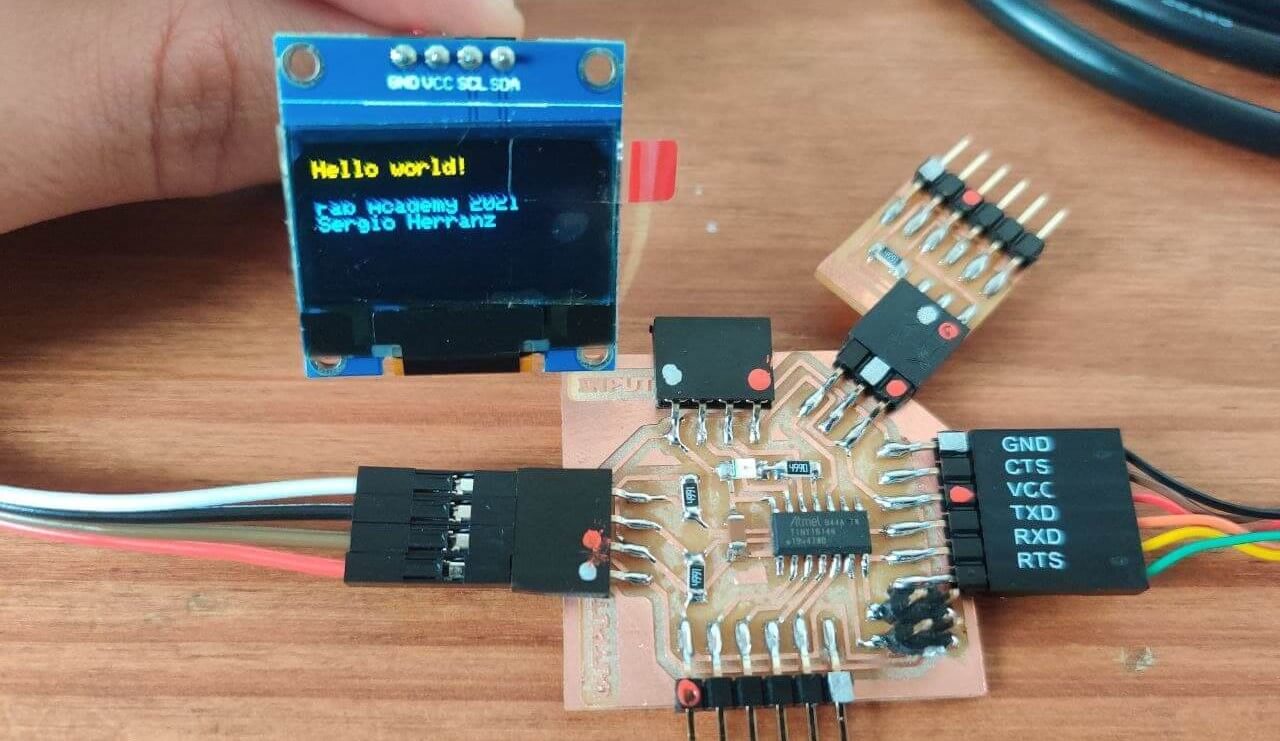
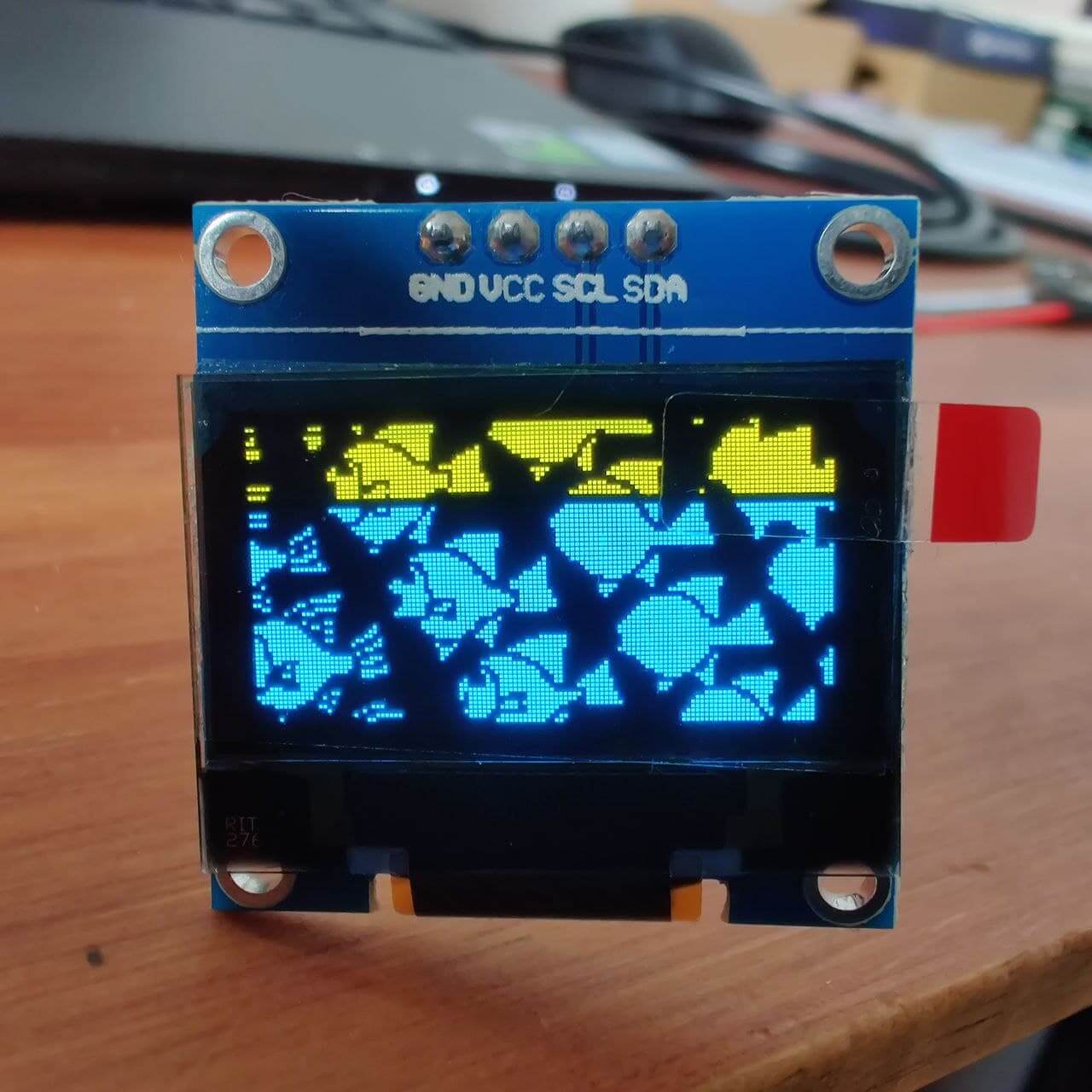
Image to oled⚓︎
I wanted to show an image on the OLED, so I followed this guide which has almost every example you could want to display on your OLED.
The process is done by transforming an image to a 128x64 px monochrome bitmap, and the using a program linked in that guide to transform the bitmap to an array in C.

These are some of the images I transformed to display them on the OLED but finally just showed the second and fourth one.


Then we have to implement that array inside the code provided in the guide.

#include <Wire.h>
#include <Adafruit_GFX.h>
#include <Adafruit_SSD1306.h>

#define SCREEN_WIDTH 128
#define SCREEN_HEIGHT 64

Adafruit_SSD1306 display(SCREEN_WIDTH, SCREEN_HEIGHT, &Wire, -1);

static const unsigned char PROGMEM image_data_Saraarray[] = {
    0x03, 0xf8, 0x1f, 0x70, 0x30, 0xff, 0x00, 0x7c, 0xfc, 0x40, 0xfc, 0x0f, 0xc0, 0xcc, 0x0f, 0xc0,
    0x01, 0xf8, 0x1c, 0xe0, 0x80, 0xff, 0x00, 0x7f, 0x3e, 0x10, 0xfc, 0x0f, 0xc0, 0x84, 0x0f, 0xc0,
    0xfc, 0x07, 0xe1, 0xef, 0x81, 0xfe, 0x00, 0x7f, 0x86, 0x1f, 0x7c, 0x0f, 0xdf, 0x00, 0x0f, 0xff,
    0xfc, 0x07, 0xc1, 0xbf, 0x81, 0xfe, 0x00, 0x7f, 0x80, 0x1f, 0x03, 0xf0, 0x3f, 0x00, 0x10, 0x3f,
    0xfc, 0x07, 0xc2, 0x3f, 0x01, 0xf9, 0xf8, 0x7f, 0x80, 0xef, 0x03, 0xf0, 0x3f, 0x02, 0x10, 0x3f,
    0xfc, 0x07, 0xc4, 0x7f, 0x04, 0x01, 0xff, 0x83, 0xc0, 0xff, 0x83, 0xf0, 0x3f, 0x03, 0xf0, 0x3f,
    0xfc, 0x07, 0xd8, 0x7f, 0xfc, 0x01, 0xff, 0xc0, 0x20, 0x79, 0x83, 0xf0, 0x3f, 0x33, 0xf0, 0x3f,
    0xfc, 0x07, 0xf8, 0xf1, 0xfc, 0x01, 0xff, 0xc0, 0x3e, 0x78, 0x03, 0xf0, 0x3f, 0x7b, 0xf0, 0x3f,
    0x7c, 0x00, 0x70, 0x81, 0xfc, 0x03, 0xff, 0xc0, 0x3f, 0xbc, 0x3b, 0xf0, 0x3f, 0xff, 0xf0, 0x3e,
    0x01, 0xf8, 0x73, 0x01, 0xf8, 0x03, 0xff, 0xc0, 0x1f, 0xcc, 0x3c, 0x0f, 0xc0, 0xff, 0xff, 0xc0,
    0x01, 0xf8, 0xee, 0x03, 0xf8, 0x03, 0xff, 0xc0, 0x1f, 0xc0, 0x1c, 0x0f, 0xc0, 0xfd, 0xef, 0xc0,
    0x01, 0xf0, 0xde, 0x03, 0xfb, 0xfc, 0x00, 0x30, 0x1f, 0xc1, 0x9c, 0x0f, 0xc0, 0xfc, 0x0f, 0xc0,
    0x01, 0xf1, 0x3e, 0x02, 0x07, 0xfc, 0x00, 0x3f, 0xdf, 0xe0, 0xfc, 0x0f, 0xc0, 0xcc, 0x0f, 0xc0,
    0x01, 0xf2, 0x3c, 0x1c, 0x07, 0xfc, 0x00, 0x3f, 0xf1, 0xe0, 0xf4, 0x0f, 0xc0, 0x84, 0x0f, 0xc0,
    0x01, 0xcc, 0x3c, 0xf8, 0x0f, 0xfc, 0x00, 0x3f, 0xf0, 0x20, 0xf3, 0x0f, 0xc0, 0x00, 0x0f, 0xc0,
    0xfc, 0x0c, 0x73, 0xf8, 0x0f, 0xfc, 0x00, 0x1f, 0xf0, 0x1c, 0x79, 0xf0, 0x3f, 0x00, 0x00, 0x3f,
    0xfc, 0x1c, 0x43, 0xf8, 0x0f, 0xfc, 0x00, 0x1f, 0xf0, 0x0f, 0x79, 0xf0, 0x3f, 0x02, 0x10, 0x3f,
    0xfc, 0x19, 0x87, 0xf8, 0x0f, 0xfc, 0x00, 0x1f, 0xf0, 0x0f, 0x99, 0xf0, 0x3f, 0x03, 0x30, 0x3f,
    0xfc, 0x1f, 0x07, 0xf0, 0x0f, 0xf8, 0x00, 0x1f, 0xf0, 0x0f, 0xc0, 0xf0, 0x3f, 0x33, 0xf0, 0x3f,
    0xfc, 0x07, 0x07, 0xf0, 0x0f, 0x87, 0xff, 0xdf, 0xf8, 0x0f, 0xc3, 0xf8, 0x3f, 0x7b, 0xf0, 0x3f,
    0xfc, 0xcf, 0x07, 0xf0, 0x70, 0x07, 0xff, 0xe0, 0x18, 0x0f, 0xc3, 0x18, 0x3f, 0xff, 0xf0, 0x3f,
    0x03, 0xcf, 0x07, 0xff, 0xe0, 0x07, 0xff, 0xe0, 0x07, 0x07, 0xc3, 0x87, 0xc0, 0xff, 0xff, 0xc0,
    0x07, 0xce, 0x0f, 0x0f, 0xe0, 0x07, 0xff, 0xe0, 0x07, 0xf7, 0xe1, 0x87, 0xc0, 0xfd, 0xef, 0xc0,
    0x07, 0x8e, 0x00, 0x0f, 0xe0, 0x07, 0xff, 0xe0, 0x07, 0xf8, 0xe1, 0x87, 0xc0, 0xfc, 0xef, 0xc0,
    0x07, 0x9e, 0x70, 0x0f, 0xe0, 0x07, 0xff, 0xe0, 0x07, 0xf8, 0x01, 0xc3, 0xc0, 0xcc, 0x0f, 0xc0,
    0x07, 0x9d, 0xf0, 0x1f, 0xe0, 0x07, 0xff, 0xe0, 0x07, 0xf8, 0x1d, 0xc3, 0xc0, 0x84, 0x0f, 0xc0,
    0x07, 0x81, 0xf0, 0x1f, 0xe0, 0x07, 0xff, 0xe0, 0x07, 0xf8, 0x1e, 0x03, 0xc0, 0x00, 0x0f, 0xc0,
    0xf8, 0x61, 0xf0, 0x1f, 0xe0, 0x07, 0xff, 0xe0, 0x07, 0xf8, 0x1f, 0x3c, 0x3f, 0x00, 0x00, 0x3f,
    0xf8, 0xe1, 0xf0, 0x1f, 0xe0, 0x07, 0xff, 0xe0, 0x07, 0xf8, 0x1f, 0x3c, 0x3f, 0x02, 0x10, 0x3f,
    0xf0, 0xe1, 0xf0, 0x1f, 0x9f, 0xf8, 0x00, 0x1e, 0x07, 0xf8, 0x0f, 0x3c, 0x3f, 0x03, 0xb0, 0x3f,
    0xf0, 0xe1, 0xf0, 0xe0, 0x1f, 0xf8, 0x00, 0x1f, 0xf8, 0x38, 0x0f, 0x1c, 0x3f, 0x03, 0xf0, 0x3f,
    0xf0, 0xe1, 0x8f, 0xe0, 0x1f, 0xf8, 0x00, 0x1f, 0xf8, 0x07, 0x8f, 0x1c, 0x3f, 0x02, 0x10, 0x3f,
    0xf0, 0xcc, 0x0f, 0xe0, 0x1f, 0xf8, 0x00, 0x1f, 0xf8, 0x07, 0xf1, 0x1c, 0x3f, 0x00, 0x00, 0x3f,
    0x0f, 0x1c, 0x0f, 0xe0, 0x1f, 0xf8, 0x00, 0x1f, 0xfc, 0x07, 0xf0, 0xe3, 0xc0, 0x00, 0x0f, 0xc0,
    0x0f, 0x1e, 0x0f, 0xe0, 0x1f, 0xf8, 0x00, 0x1f, 0xfc, 0x07, 0xf0, 0xe3, 0xc0, 0x00, 0x0f, 0xc0,
    0x0f, 0x1e, 0x0f, 0xe0, 0x1f, 0xf8, 0x00, 0x1f, 0xf8, 0x07, 0xf0, 0xe3, 0xc0, 0x84, 0x0f, 0xc0,
    0x0f, 0x1e, 0x0f, 0xe0, 0x1f, 0xf8, 0x00, 0x1f, 0xf8, 0x07, 0xf0, 0xe3, 0xc0, 0xfc, 0xcf, 0xc0,
    0x07, 0x1e, 0x0f, 0xe0, 0x1f, 0xf8, 0x00, 0x1f, 0xf8, 0x07, 0xf0, 0xc3, 0xc0, 0xfd, 0xff, 0xc0,
    0x07, 0x1e, 0x0f, 0xe0, 0x1f, 0xf8, 0x00, 0x1f, 0xf8, 0x07, 0xf0, 0xc3, 0xc0, 0xff, 0xff, 0xc0,
    0x71, 0x1e, 0x0f, 0xe0, 0x1f, 0xf8, 0x00, 0x1f, 0xf8, 0x07, 0xf0, 0xcc, 0x3f, 0xff, 0xf0, 0x3f,
    0xf8, 0x62, 0x0f, 0xe0, 0x1f, 0xf8, 0x00, 0x1f, 0xf8, 0x07, 0xf7, 0x3c, 0x3f, 0xff, 0xf0, 0x3f,
    0xf8, 0x61, 0xff, 0xf0, 0x1f, 0xf8, 0x00, 0x1f, 0xf8, 0x04, 0x1e, 0x3c, 0x3f, 0x7b, 0xf0, 0x3f,
    0xf8, 0x71, 0xf0, 0x00, 0x1f, 0xf8, 0x00, 0x1f, 0xf9, 0xf8, 0x1e, 0x3c, 0x3f, 0x03, 0xf0, 0x3f,
    0xf8, 0x31, 0xf0, 0x0f, 0xe0, 0x18, 0x00, 0xe0, 0x07, 0xf8, 0x1e, 0x78, 0x3f, 0x02, 0x10, 0x3f,
    0xfc, 0x30, 0xf8, 0x0f, 0xf0, 0x07, 0xff, 0xe0, 0x07, 0xf8, 0x1e, 0x78, 0x3f, 0x00, 0x00, 0x3f,
    0x78, 0x30, 0xf8, 0x0f, 0xf0, 0x07, 0xff, 0xe0, 0x07, 0xf0, 0x1e, 0x78, 0x3f, 0x00, 0x0f, 0xc0,
    0x03, 0xc0, 0xf8, 0x0f, 0xf0, 0x07, 0xff, 0xe0, 0x07, 0xf0, 0x3d, 0x87, 0xc0, 0x00, 0x0f, 0xc0,
    0x03, 0xe7, 0xf8, 0x0f, 0xf0, 0x07, 0xff, 0xe0, 0x07, 0xf0, 0x33, 0x0f, 0xc0, 0x84, 0x0f, 0xc0,
    0x03, 0xe7, 0x88, 0x07, 0xf0, 0x07, 0xff, 0xe0, 0x0f, 0xf0, 0xc3, 0x0f, 0xc0, 0xec, 0x0f, 0xc0,
    0x03, 0xe3, 0x82, 0x07, 0xf0, 0x07, 0xff, 0xe0, 0x0f, 0xf7, 0xc7, 0x0f, 0xc0, 0xfc, 0xcf, 0xc0,
    0x03, 0xe3, 0x83, 0xe7, 0xf0, 0x07, 0xff, 0xe0, 0x0f, 0x9f, 0x86, 0x0f, 0xc0, 0xfd, 0xef, 0xc0,
    0x01, 0xf1, 0xc3, 0xf8, 0x78, 0x07, 0xff, 0xc0, 0x00, 0x1f, 0x86, 0x0f, 0xc0, 0xff, 0xff, 0xc7,
    0x7c, 0x09, 0xc3, 0xf8, 0x07, 0x03, 0xff, 0xcf, 0xf0, 0x1f, 0x81, 0xf0, 0x3f, 0x7f, 0xf0, 0x3f,
    0x7c, 0x0f, 0xe1, 0xfc, 0x07, 0xfc, 0x00, 0x3f, 0xf0, 0x1f, 0x33, 0xf0, 0x3f, 0x7b, 0xf0, 0x3f,
    0x7c, 0x0f, 0x21, 0xfc, 0x07, 0xfc, 0x00, 0x3f, 0xe0, 0x3f, 0xf3, 0xf0, 0x3f, 0x03, 0xf0, 0x3f,
    0x7c, 0x0f, 0x01, 0xfc, 0x07, 0xfc, 0x00, 0x3f, 0xe0, 0x3c, 0xe3, 0xf0, 0x3f, 0x03, 0x30, 0x3f,
    0x7c, 0x07, 0x8e, 0xfe, 0x03, 0xfc, 0x00, 0x3f, 0xe0, 0x21, 0xe3, 0xf0, 0x3f, 0x02, 0x10, 0x3f,
    0x7c, 0x07, 0x8f, 0x3e, 0x03, 0xfc, 0x00, 0x3f, 0xe0, 0x81, 0xc3, 0xf0, 0x3f, 0x00, 0x00, 0x3f,
    0x81, 0xf8, 0xc7, 0x06, 0x03, 0xfc, 0x00, 0x3f, 0xc7, 0x83, 0xdc, 0x0f, 0xc0, 0x00, 0x0f, 0xc0,
    0x81, 0xf8, 0x27, 0x80, 0x81, 0xfc, 0x00, 0x3f, 0xbf, 0x83, 0x7c, 0x0f, 0xc0, 0x84, 0x0f, 0xc0,
    0x81, 0xf8, 0x3b, 0x80, 0xff, 0xfe, 0x00, 0x20, 0x3f, 0x04, 0x7c, 0x0f, 0xc0, 0xfc, 0x0f, 0xc0,
    0x81, 0xf8, 0x1f, 0xc0, 0xfe, 0x01, 0xff, 0x80, 0x3f, 0x08, 0xfc, 0x0f, 0xc0, 0xfc, 0x0f, 0xc0,
    0x81, 0xf8, 0x1e, 0x40, 0x7e, 0x01, 0xff, 0x80, 0x7f, 0x30, 0xfc, 0x0f, 0xc0, 0xfd, 0xef, 0xc0,
    0x81, 0xf8, 0x1f, 0x30, 0x7f, 0x01, 0xff, 0x80, 0x7f, 0xf0, 0xfc, 0x0f, 0xc0, 0xff, 0xff, 0xc0
}

void setup() {
    Serial.begin(115200);

    if(!display.begin(SSD1306_SWITCHCAPVCC, 0x3C))
        Serial.println(F("SSD1306 allocation failed"));

    // Clear the buffer.
    display.clearDisplay();

    // Draw bitmap on the screen
    display.drawBitmap(0, 0, image_data_Saraarray, 128, 64, 1);
    display.display();
}

void loop() {

}
This is the final result of displaying an image, transformed to a bitmap and the to a C array to make it readeable for the micro.

Hero shot⚓︎
This a compilation of some of the shots I took of displaying things on the two displays, also including part of the Adafruit full test for an OLED screen, which you can find at the end of the video.
Group assignment⚓︎
This week’s group assignment consists of measuring the power consumption of our output device. In my case, as I have used two displays with different technology and one of their main differences is the energy efficiency, I think it will be interesting to see the result and establish a comparison with the technical data we have seen at the beginning about them.
Danger
To measure the consumption of a device we must place an element that is capable of measuring the current intensity that passes through it. Therefore, to measure current we must always do it in series, using our measuring element as a means to close the circuit. This makes it somewhat dangerous if we are working with devices that require a lot of power. Safety is a very important element, because as Neil explained during the class, a current greater than 10mA could shock us, and to a greater extent lead to fibrillation or death. In this week’s schedule, it is the first topic we look at. To make sure I was going to make the measurements correctly, I first made a small electrical schematic, as shown below.


Power consumption⚓︎
In my case I am going to use a multimeter connecting GND to the black connector and the current to the low current port, because although there is a port to measure current, it is for higher values and trying to measure data on it gave me very low measurements. In this case I measured the LCD screen at a maximum range of 200mA and the OLED at 20mA. Taking into account that the voltage we have on the board is 5V (it can have small variations but we take this value as standard) we calculate the power consumption with the formula P(W) = V(V) x I(A).
I = 45.5mA = 0.0455A -> P(W) = 5 x 0.0455 = 0.2275W

I = 15.64mA = 0.01564A -> P(W) = 5 x 0.01564 = 0.0782W

Conclusions⚓︎
With the results in hand we can do a ratio to see how much more one device consumes versus the other. In this case operating 0.0782 / 0.2275 = 0.347 -> 0.347 x 100 = 34.7% we get that the OLED screen consumes 34.7% of LCD total power or 65.3% less which is the same. This difference is very high, almost twice as high as the technical specifications of each technology, but we could find an explanation for it:
- The first argument, the size of both screens is quite different, being the LCD approximately 2.5x the size of the OLED, so if we calculate the percentage based on this, the figure would be very similar to the one exposed in the technical comparison at the beginning.
- The second is the brightness level of the LCD screen, which is adjustable with a potentiometer on the back and could reduce its power consumption, but in terms of comparison both had a similar brightness.
- And the third, in this case in favour of OLED, is that the image displayed on it leaves almost the entire screen on, so the power consumption is high for this type of device. In the case of displaying only a few lines of text (the most common for this type of device) consumption would be much lower since the rest of the pixels would be off, highlighting one of the main features of this technology, while in the case of LCD we would need to have the backlight on in the same way.
Files⚓︎
- Schematic design from Eagle of the Output board (
.sch): file - Board design from Eagle of the Output board (
.brd): file - Traces of the Output board (
.png): file - Exterior of the Output board (
.png): file - Arduino code for finding the I2C port(
.ino): file - Arduino code for the LCD(
.ino): file - Arduino code for the OLED(
.ino): file - Arduino code for the bitmap image for the OLED(
.ino): file