
Input Devices
WEEK 10
(07/04/2021 18:28 p.m.) Wednesday afternoon. After two weeks of hard effort, we have managed to present our machine on time in front of the whole class! From the fab lab UE Madrid, Alberto and me presential; and Sergio and Mickaël remotely, we have managed to finish off the last details of the machine, the video and this assigment´s slice.
During the presentation, Alberto has exposed the machine and the situation in which we find ourselves to make it. Neil, seemed very concerned about Mauro's situation, and to our surprise ... Mauro appeared at the presentation! 😍😍 Since yesterday, he left the hospital. And little by little, he is regaining his strength 💪💪. It was a very pleasant surprise! 💚
This week, we return to electronics again ... chan, chan, chan (dramatic sound)., but this time to integrate and program sensors.
(08/04/2021 10:38 a.m.) On this occasion, Nuria has recommended, to each of us, we work with the sensors that we are likely to use for our final project. I'm a little scared, as I usually am in these electronic weeks. But this time I feel much more relaxed and focused than other weeks.
(10/04/2021 23:23 p.m.) Also, this week in Madrid has celebrated the Fashion Week! and my friend and mentor Raquel Buj (Zap & Buj) has presented her first solo collection, that she called NIDOS (Nests) . I am very proud of all the work she has done, and the opportunity that she has given me to be able to see and participate in her runway. 😍😘
With this adrenaline rush through the runway and Mauro returns to our crew again, I must commemorate this week with a song with a lot of energy, The Boys are Back by Dropkick Murphys . ☘☘
It's time to get ready for that song and dance
Let's go my friends, it's time to take a chance
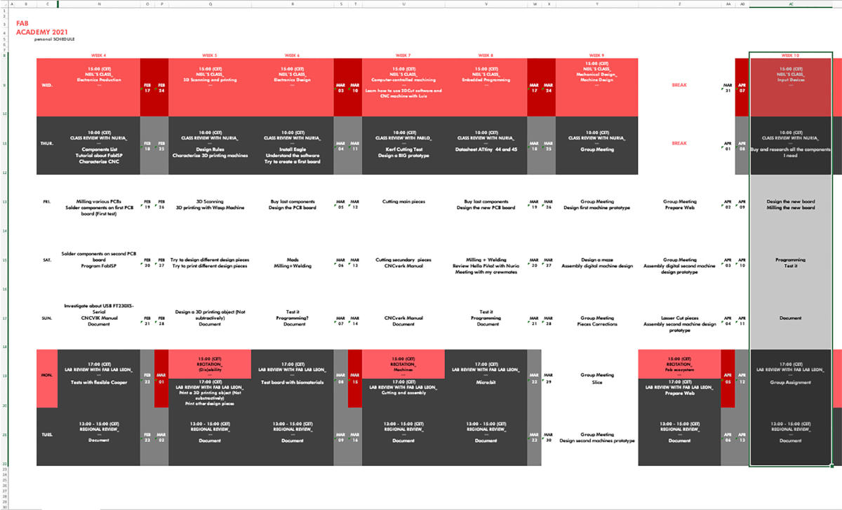
Organizing tasks
Like previous week, we have two types of assignments, one's group and other individual. So as usual, I organize my schedule and here the following Evaluation Criteria that we have to approach to complete the Assignment:
- ✓ Probe an input device(s)'s analog and digital signals
- ✓ Document what we learned from interfacing an input device(s) to microcontroller to the measured results
- ✓ Document our work
- ✓ Documented our design and fabrication process
- ✓ Measure something: add a sensor to a microcontroller board that we have designed and read it
- ✓ Explained the programming process/es we used
- ✓ Explained problems and how you fixed them
- ✓ Included our source codes.
Extra credit
- ✓ Include a "hero shot" of our board
Group Assignment
- TESTING ANALOG LEVELS WITH THE OSCILOSCOPE
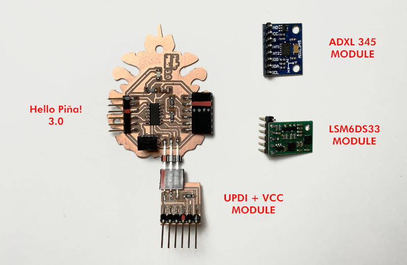
(14/04/2021 09:37 a.m.) During Wednesday morning, with the Head of fab lab IED Madrid, we have measured the analog levels of my board with my two accelerometer sensors that I have: the Pololu LSM6DS33 module and the ADXL 345 module.
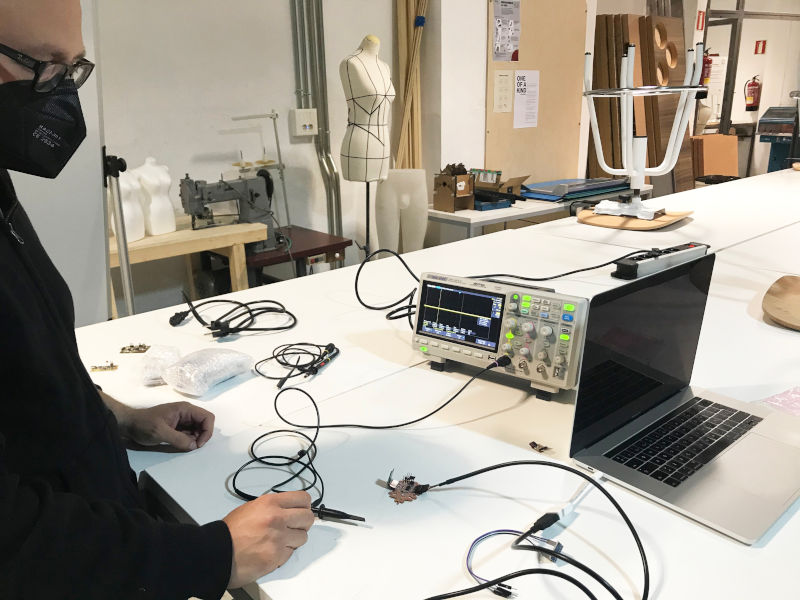
(14/04/2021 10:12 a.m.) With the LSM6DS33 sensor, there have been more issues, the signal that appeared was constant, and we don´t know exactly why. 🤷♀️. But with the ADXL 345 sensor we have measured the input and output signal of the board and the accelerometer.
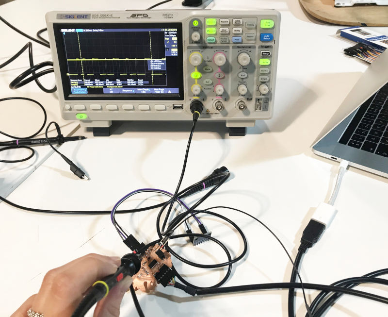
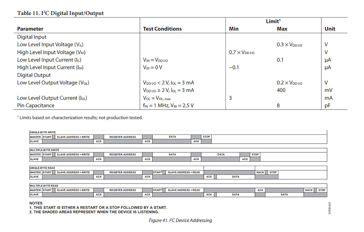
According to the Accelerometer Datasheet, the signal that my oscilloscope is giving me is a mix of information related to these four analog signals. The ideal way would be to see the breakdown of waves with an analog analyzer, like Adrián showed us in the local Review. But, unfortunately we don't have one in fab lab IED.
Here, you can see a video when the levels vary as I move the accelerometer:
Individual Assignment
HELLO PIÑA! 3.0 ACCELEROMETER
-
_ BOARD DESIGN
For this week in which we have to incorporate a sensor, I want to work with an accelerometer that will need as part of my final project.
For my new board, I wanted to go one step further and use the new generation of ATtiny microcontrollers, so I am going to use an Attiny 1614.
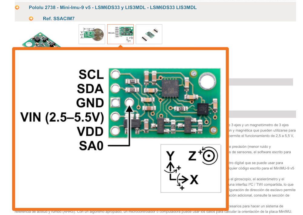
Following Neil's schematic board of a 6-axis accelerometer with gyroscope, Hello LSM6DS33, I am about to design my new board in Eagle.
(08/04/2021 11:06 a.m.) During our local review, Adrián has suggested to us (to get ahead of the Networking and Communications week), that we integrate a Serial Bus connector in our boards to be able to reuse the boards in the next weeks.
(08/04/2021 12:21 p.m.) After our local review, I got down to work, looking at the fab lab IED Madrid inventory, what components it had and which ones I would need.
At the beginning, my idea was to integrate and solder the accelerometer chip inside the new board I am going to design. Nuria warned me that these types of chips were very small and difficult to solder, and she sent me a photo to give me an idea of the size.
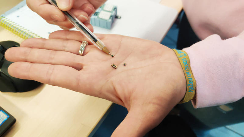
Seeing the complexity that could have soldering the component (knowing my clumsiness with electronics) 😅 I opted to use the Pololu LSM6DS33 accelerometer module.
For the new board I want to design, I'm going to take the next step and use the new generation ATtiny 1614 microcontrollers 💪💪.
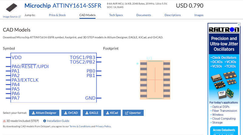
To design the board in Eagle, we need the schematic and footprint of the new microcontroller, because it is not in the fab library. From Adrián's webpage, I saw he got the footprints from this Octopart page, where you can download and later update the driver footprints.
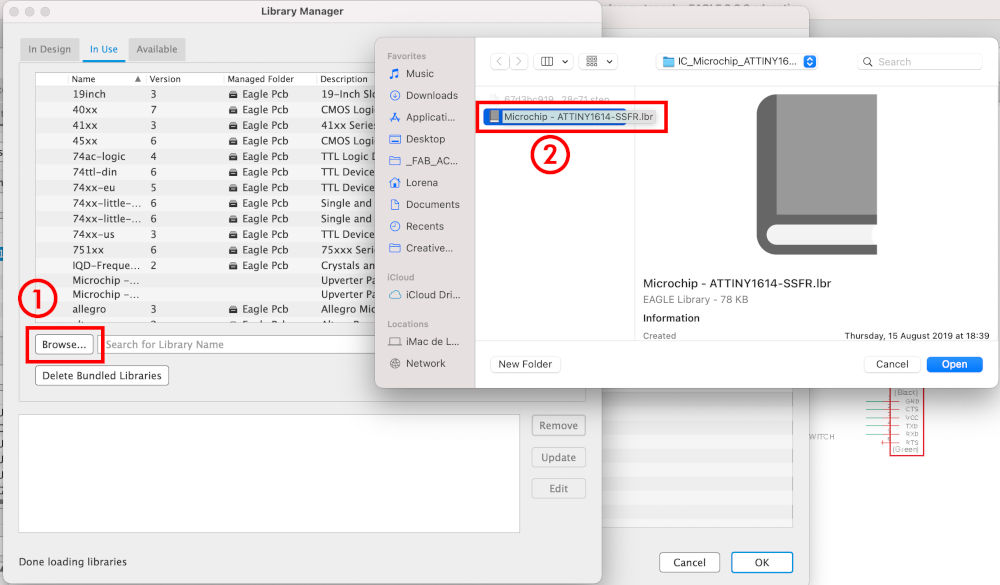
Once downloaded, I am going to add the footprint to my library. For that, I open Eagle and go to: Options > Directories > Browse > Libraries , I paste the download folder of my new microcontroller.
Once added, I am going to start with the schematic. In Add Part, I look for my microcontroller, but I find the footprints have a rectangular outline around them (which won't let me route the tracks on my board) and the pins are slightly small). 🙃
So I have to modify it. From this window I go to Open Library Manager > I select the library of my new microchip and press Edit.
When pressing this option, two windows appear. I have to close the first one that appers ADD, and I stay in the window where the folder of our ATtiny1614 library appears with its three built-in microcontrollers.
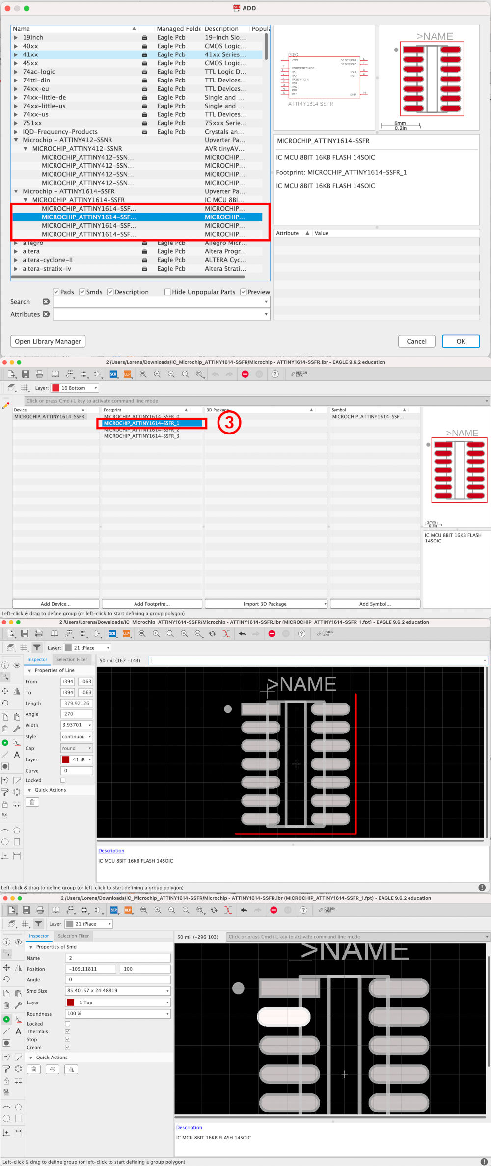
Since I really have no idea which of the three footprints is the best, I double click on the middle option.
Suddenly a new window appears, which allows us to add or remove layers of our microcontroller or component that we are going to modify.
The first thing I do is, select the perimeter rectangle and delete it. And then, I select the microcontroller pins one by one, and increase their length to be able to solder them better on the board.
This process, a priori, seems simple. But having no idea how to do it, it took me a lot of time to research and understand what I was doing. 😅
(08/04/2021 18:36 p.m.) During the board design, on Neil's original LSM6DS33 module board, he directly connects the communication of SDA and SCL pins accelerometer with the microcontroller. But, talking to Adrián about the board, he recommended adding 4.99KΩ resistors between the microcontroller pins and the SDA and SCL pins, to limit the current in devices with I2C communication. Following this schematic:.
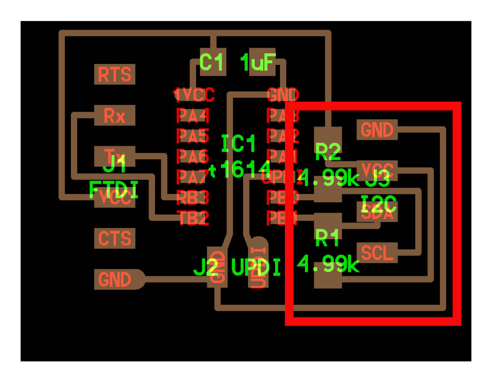
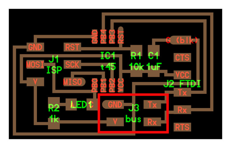
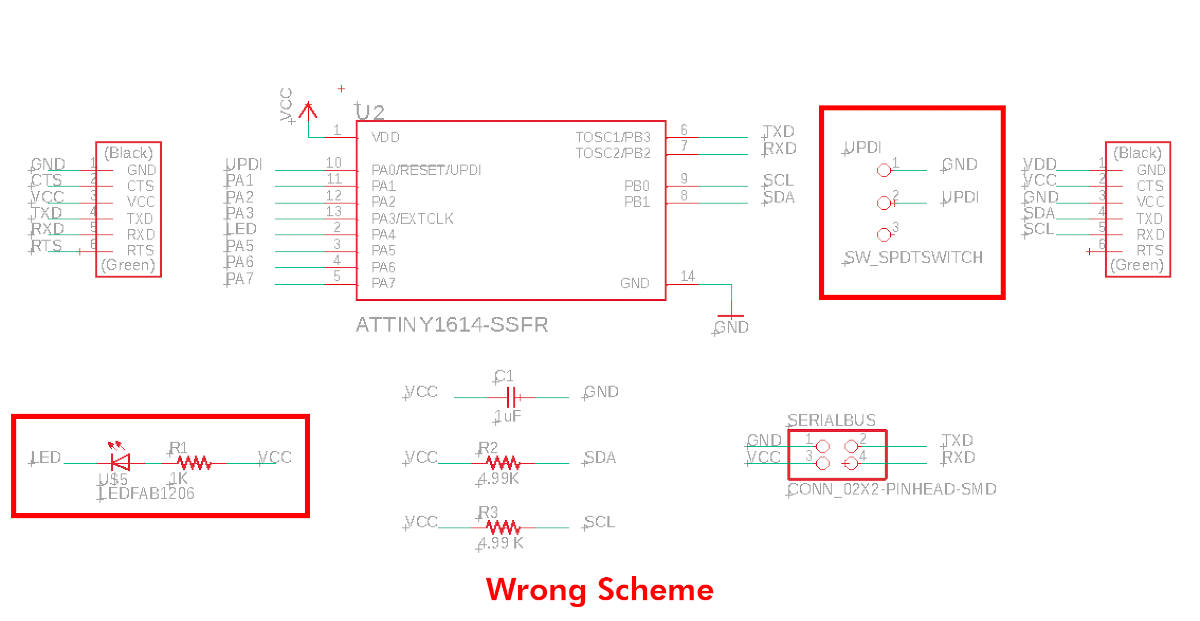
This was my first schematic designed on Friday. (10/04/2021 09:18 a.m.) But, on Saturday with Alberto at Fab Lab UE Madrid, II realize that I made two mistakes. One was that I routed the LED I had incorporated backwards, and on the other, I did not have a Serial UPDI module to program my new board. 😬😅
When Alberto and me realized this little detail, we spoke with our crewmate Mickaël and Adrián, and they did not say that we had to mill our Serial UPDI to program the new microcontroller.
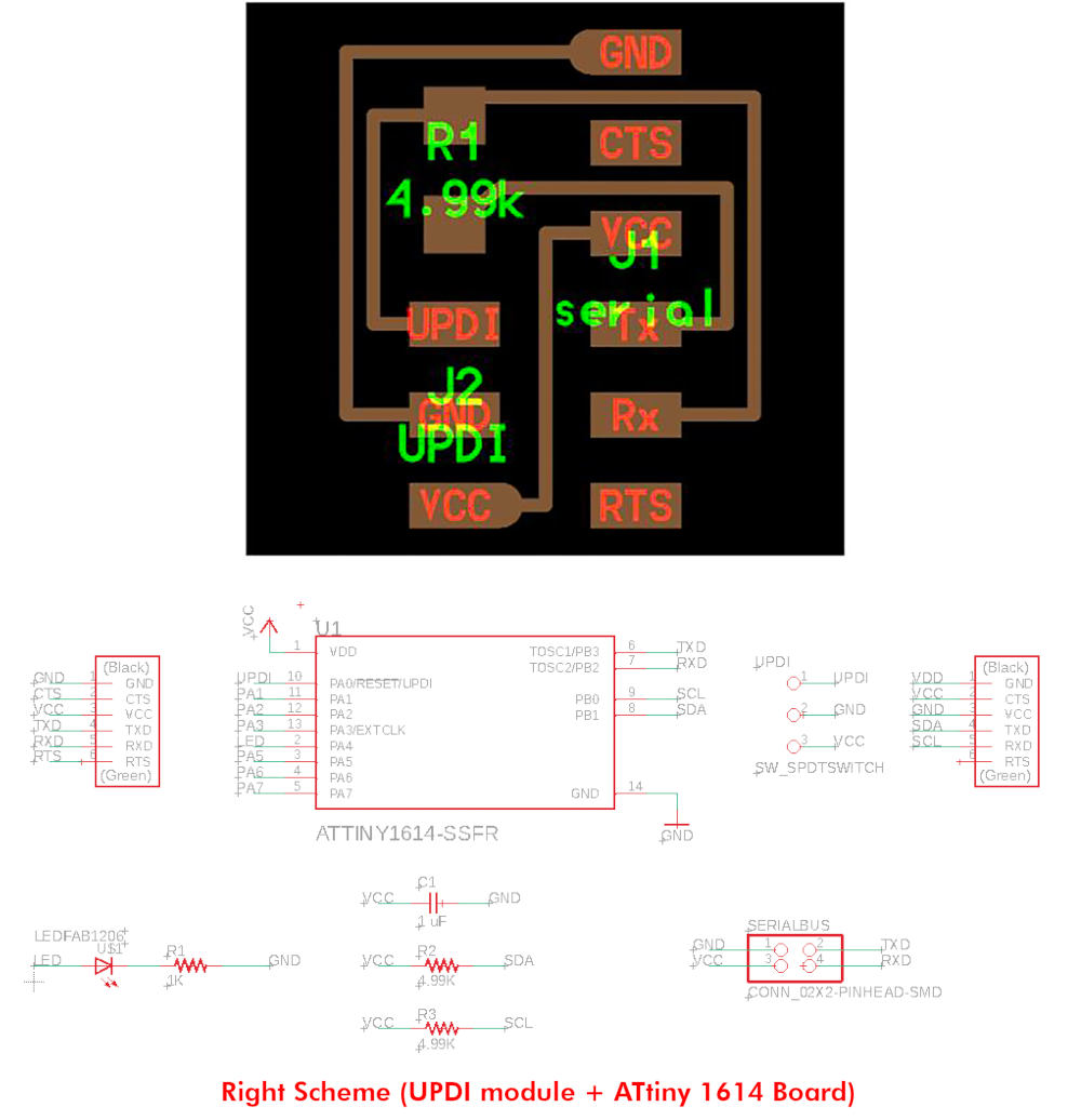
To do this, we went to Adrianino's webpage 😍🦋, where Adrián designed a UPDI + VCC module to program his board (which is also made with an ATtiny 1614 microcontroller).
This is Neil's original schematic, but we opted for the Adrián´s serial had made for Adrianino 💚💚.
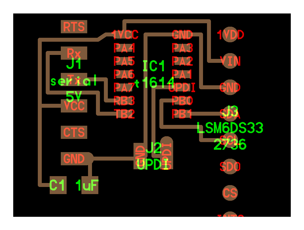
All mistakes corrected, this is the final schematic of my new board!
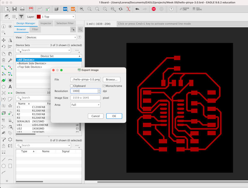
I exported the image in png, following the criteria of the previous week of Electronics Design, but I still have the same problem on Mac, since when exporting it the image is oversized and I have to readjust the image manually in Illustrator 😪😪.
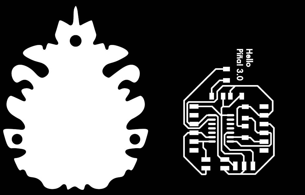
Following the idea of my previous boards, I am going to make the Hello Piña! 3.0, but this time with a more organic exterior design in the shape of the pinecone. Here you can see the files: Hello Piña! 3.0 Traces. PNG + Hello Piña! 3.0 Outlines. PNG .
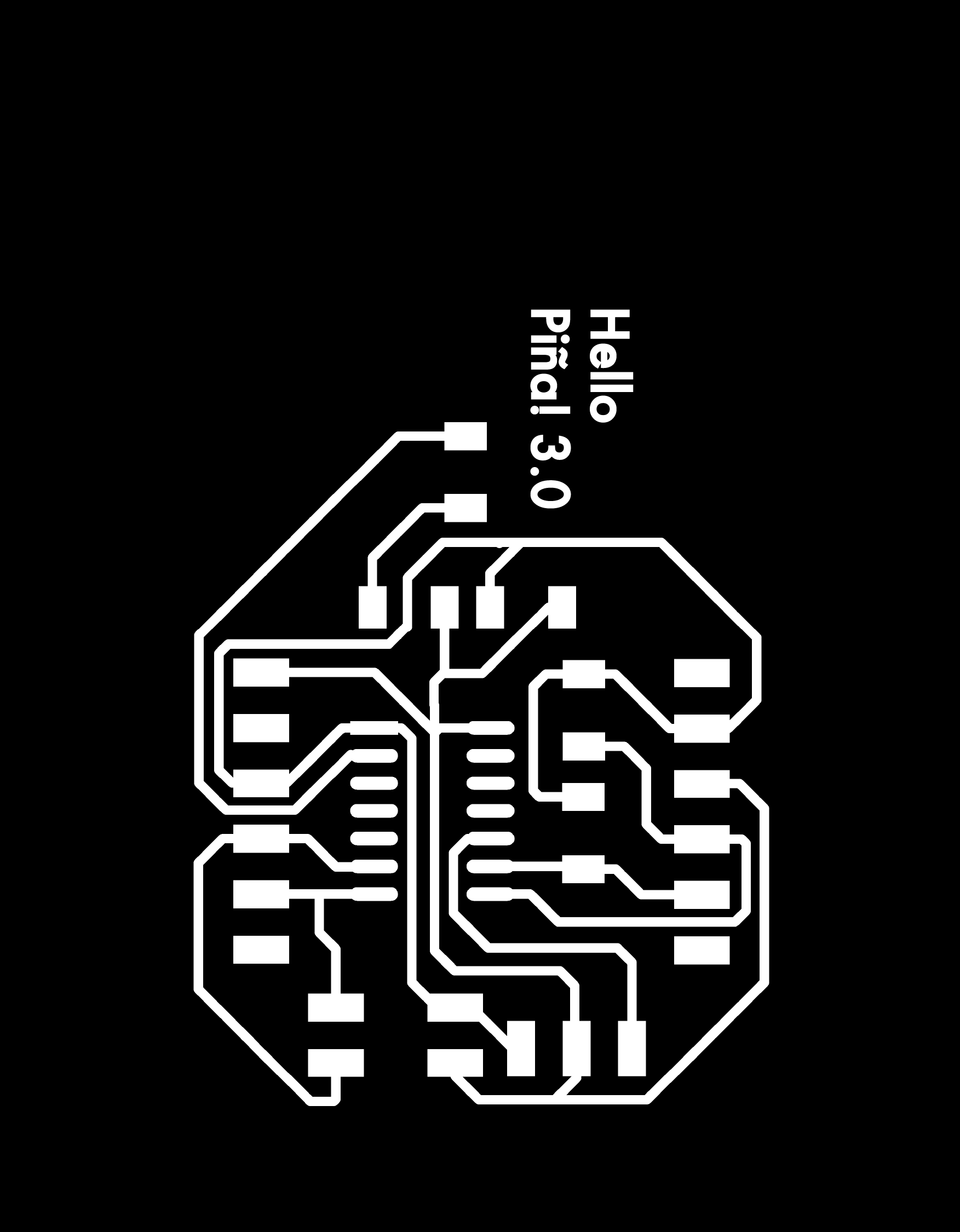
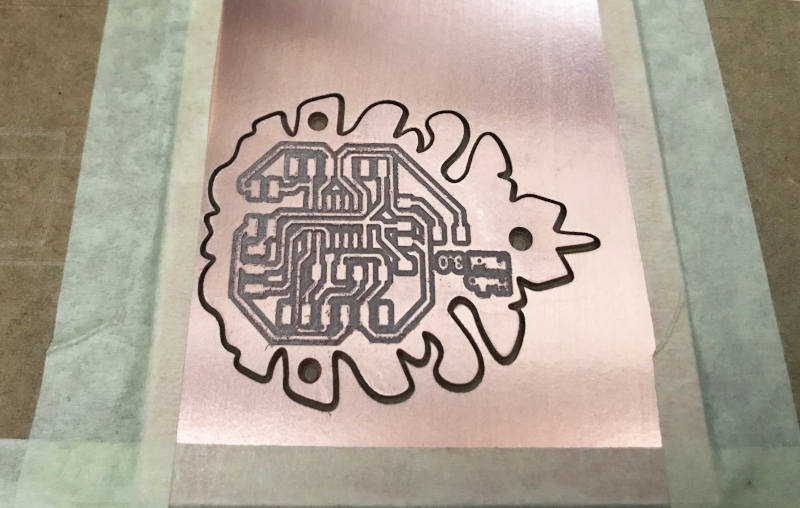
When I started to mill the board I had some problems along the way. Since the bed of the MDX-400 milling machine of the fab lab UE Madrid is slightly out of calibration at the Y axis. So I changed the orientation of the PCB board, and I got a more optimal milling.
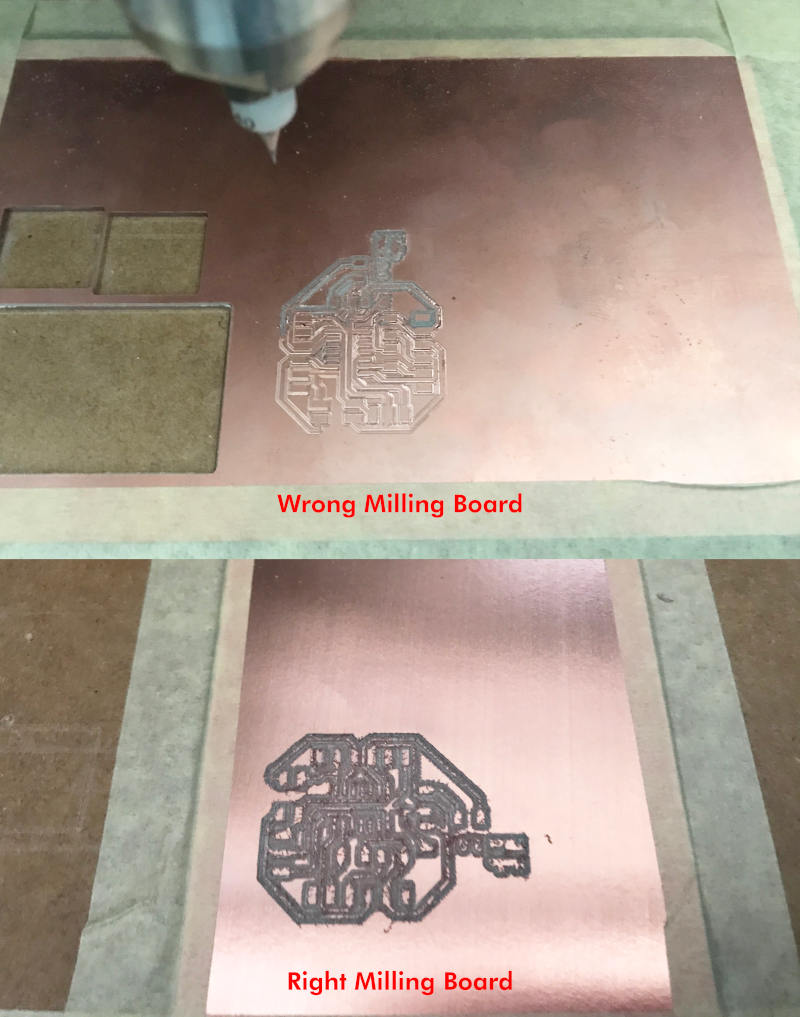
This is the end result when milling the new Hello Piña! 3.0 😍😍
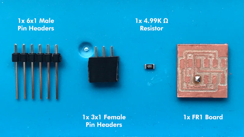
Once we have all the boards milled, I am going to solder my new Serial UPDI + VCC module and my new Hello Piña! 3.0.
For the Serial UPDI + VCC module we need:
- 1x 4.99KΩ resistors
- 1x 1x6 male pin header
- 1x 1x3 female pin header
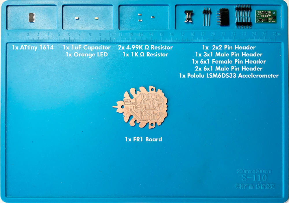
And for the new Hello Piña! 3.0 I need:
- 1x ATtiny1614
- 1x 1uF Capacitor
- 1x orange LEDs
- 2x 4.99KΩ resistors
- 2x 1KΩ resistors
- 1x 1x3 male pin header
- 2x 1x6 male pin header
- 1x 2x2 male pin header
- 1x 1x6 female pin header
- 1x Pololu LSM6DS33 Module
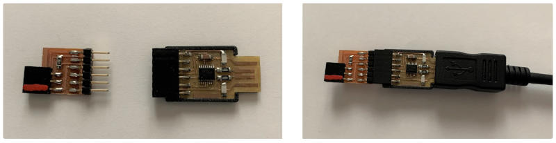
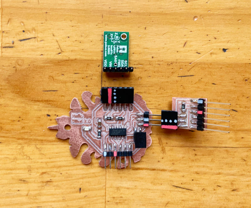
Once all the components have been soldered, this is the final result of the new Hello Piña! 3.0, the Serial UPDI + VCC and the LSM6DS33 module.
-
_ TRY TO PROGRAMMING ATTINY 1614
To program the new board with the ATtiny 1614, I have followed the steps that Adrián explained in the January Bootcamp, where he presented Adrianino 😍. So following his tutorial the first thing I do is:
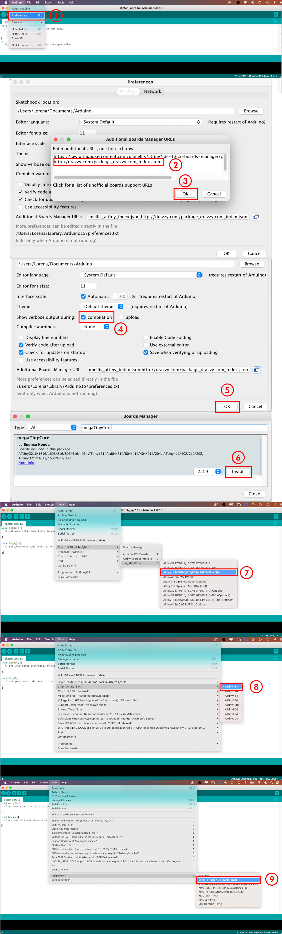
From the Spence Konde tutorial, I copy this board manager URL: http://drazzy.com/package_drazzy.com_index.json.Then, in Arduino IDE> Preferences> Additional Boards Manager URLs, we paste the URL. In Adrián's tutorial, he tells us it is important that once we have pasted the URL in Show verbose output during: we select Compilation. Once this is done, we go to Boards Manager, and we look for megaTinyCore, we download version 2.2.9 and install it.
Once installed, in Tools, we select:
- Boards > MegaTinyCore > ATtiny1614
- Chip > ATtiny1614
- Programmer > Serial Port and 4.7k (pyupdi style)
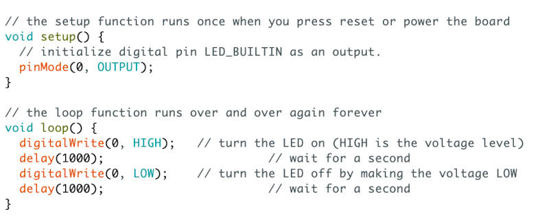
ATo begin, I am going to load a simple Blink code onto my board, as I do traditionally to check if my board works or not. 😅
Once ready, to program I connect: my new Hello Piña 3.0! through the Serial UPDI + VCC with the FTDI to the computer.
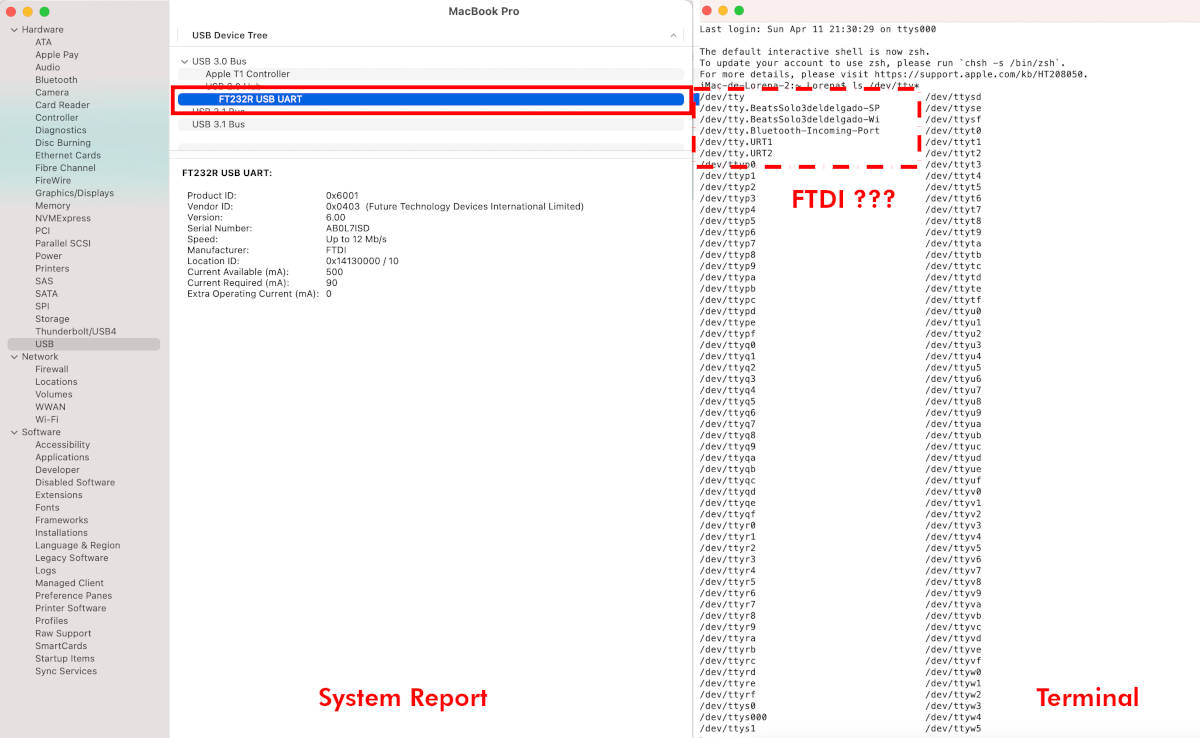
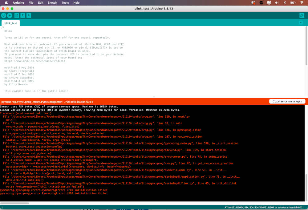
When I Upload the code, my computer asks me to select an output Port. In the list that appears on my screen, initially none of the devices that appears appear to be my FTDI. 😳😳

As in other debugging occasions, I go to the apple icon> About this Mac> System Report> USB, to check if my FTDI is recognized by my computer. At the beginning, the FTDI is connected to the computer. But after some debugging sessions with Nuria, we check at the terminal if my FTDI by the computer using the command line: ls //dev/tty *. However, the terminal does not recognize the FTDI. Suspicious! 🤔🤨
With this problem, Nuria asked me if I had installed the FTDI drivers on my computer, through this page. Weeks before I had installed them, but I decided to reinstall them again to see if this was the problem. After several hours of reinstallation and debugging, the FTDI still does not recognize my laptop.😩😩
I report the problem to Nuria, and she advises me to try another FTDI to see if my own FTDI cable is the issue. So, I go back to the fab lab UE Madrid, where Alberto has managed to program his board with some home FTDI that he has at the fab lab. 😂
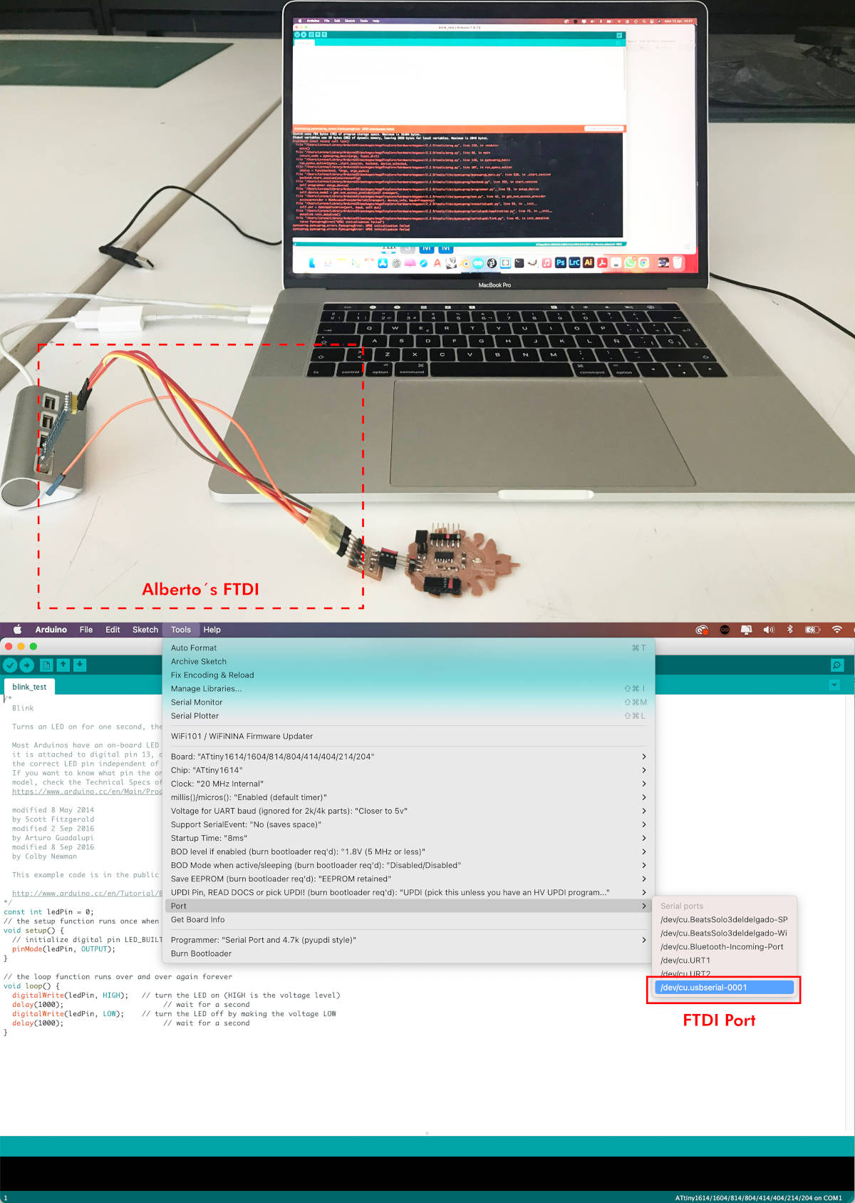
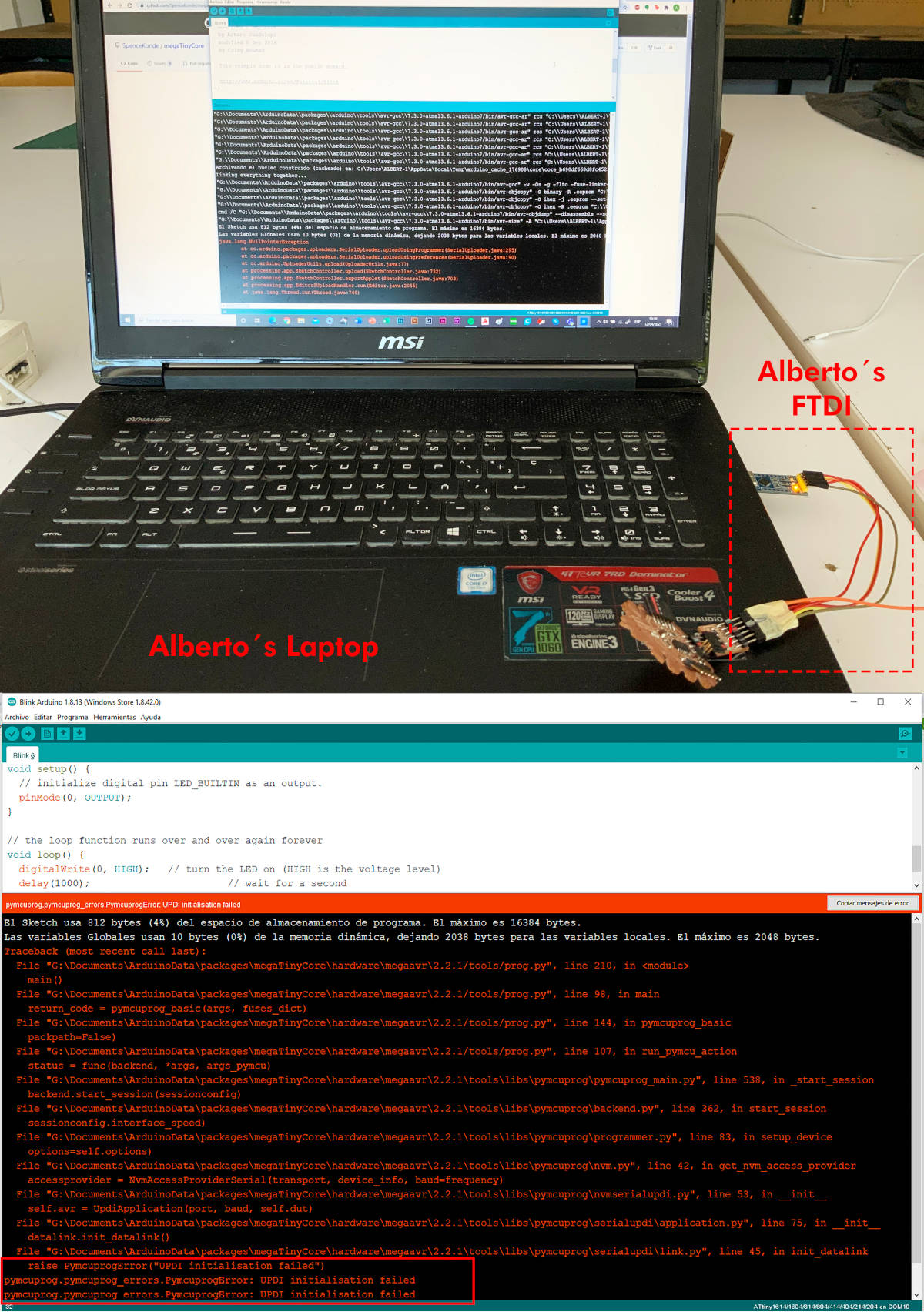
Here I check my computer recognizes Alberto's FTDI output port! 🤩, but when I go to load the code, Arduino informs me that there is a problem with the FTDI, and the code cannot be loaded. 😱😱😱
Given the problem, Alberto lends me his laptop, and with his FTDI, I carry out the same process to connect and load the Blink code ... BUT! I have the same problem again, and the code cannot be loaded. 🤯🤯🤯 What's going on?!?!?! 😡😡😭😭
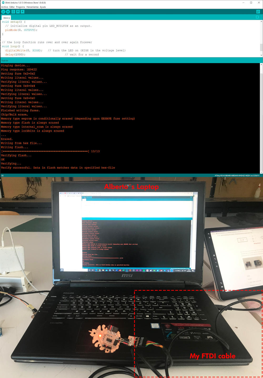
After several hours of despair... with Alberto's computer I substitute his FTDI for my FTDI, and finally... I GOT TO PROGRAM MY NEW HELLO PIÑA! 3.0 !!!!! 😍😍🎉🎉🎉🎉🎊🎊🎊
-
_ TRY TO PROGRAMMING ACCELEROMETER CODE PART I (POLOLU LSM6DS33 MODULE)
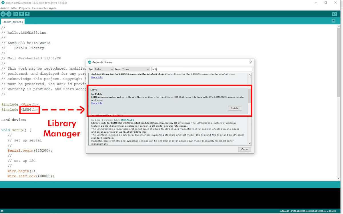
To start programming my accelerometer (using Alberto's laptop and my FTDI from now on), the first thing I do is connect the LSM6DS33 module to my Hello Piña! 3.0. And to program the board I'm going to use Neil´s code made for this module.
Once I copy it to the Arduino IDE, I am going to download the Pololu LSM6 library from Library Manager, to be able to load and read the accelerometer data.
Once the code is downloaded and loaded onto the board, I open the Monitor, and I see the monitor do not do any reading. 😕😕
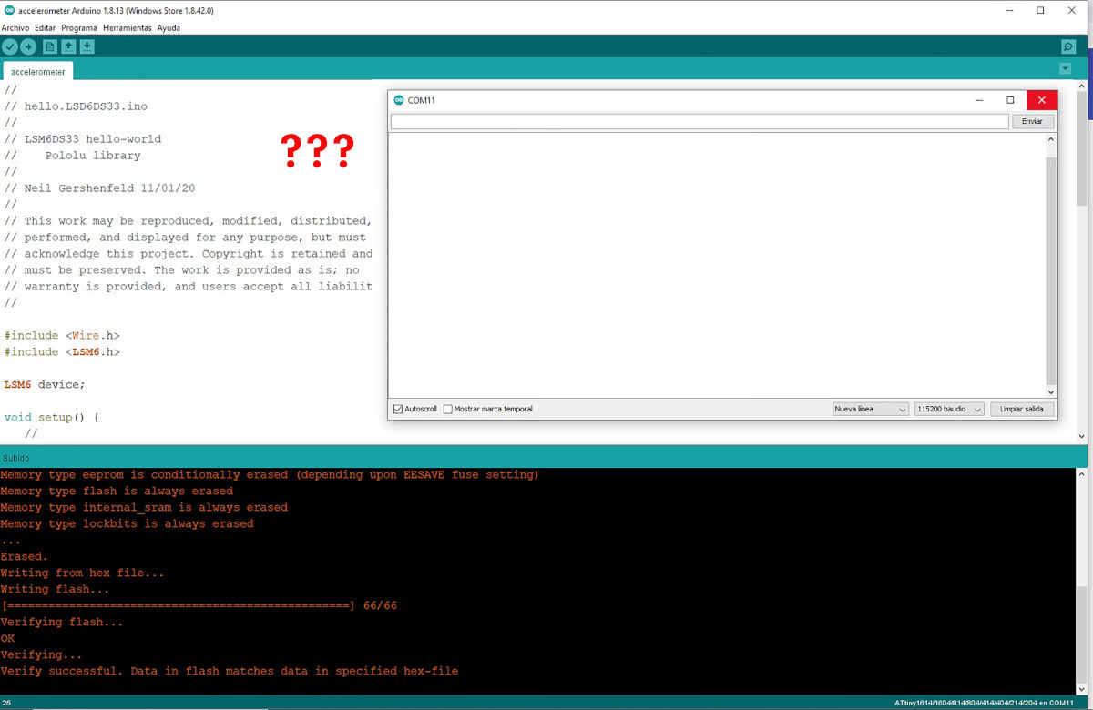
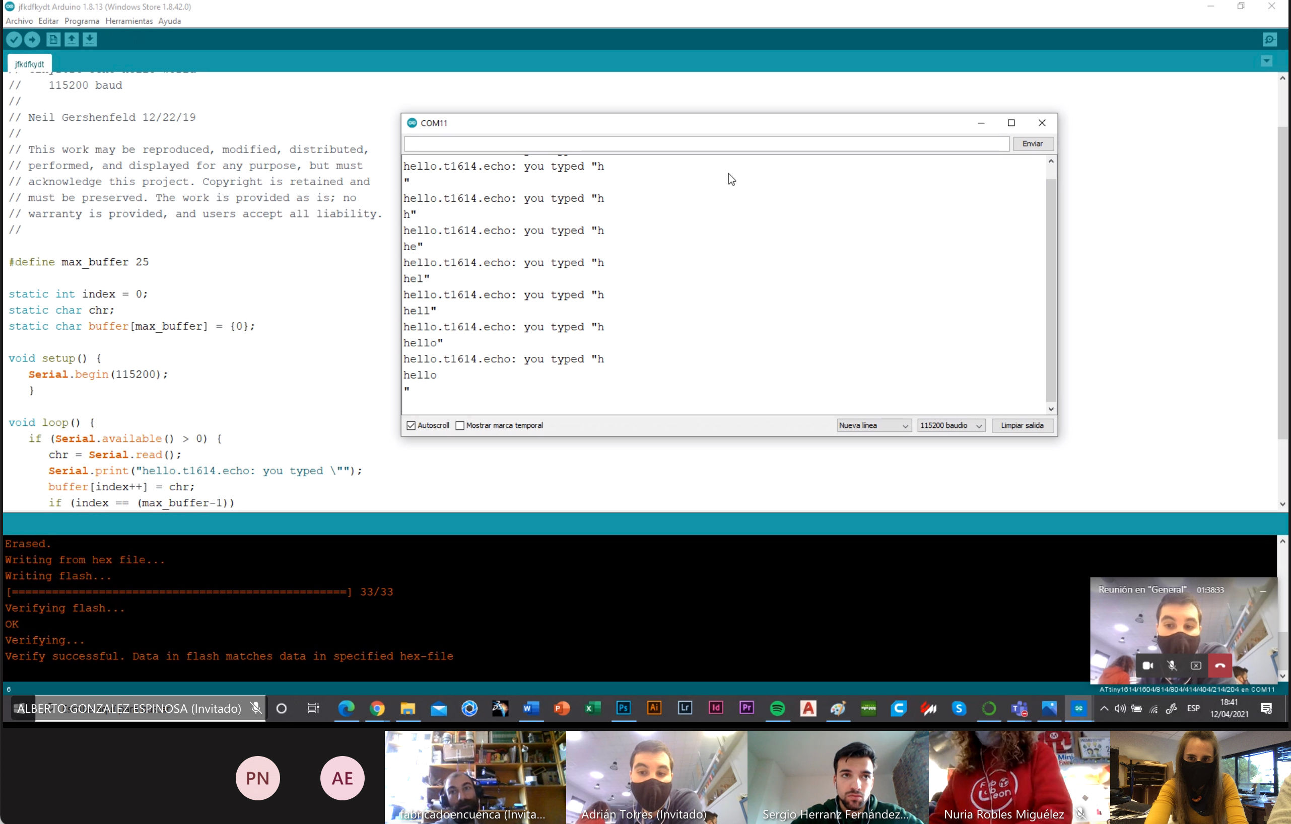
(12/04/2021 17:16 p.m.) In our local review on Mondays, I report the problem to Adrián + Nuria + Pablo, and I show them, in situ, my problem. The first thing Adrián recommends me is load a Hello.World code, to check if the problem comes from the module or the microcontroller.
When I do it, it seems to work! therefore the microcontroller is safe!. But retesting Neil's accelerometer and code, we see that it still doesn't work. 😤😤
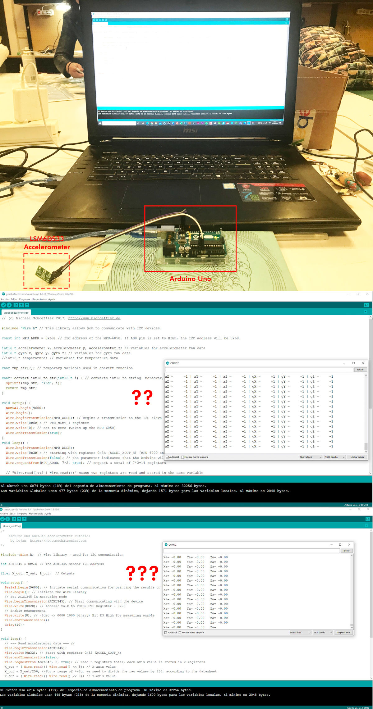
After our review, I start to do a debugging session with an Arduino One and the LSM6DS33 accelerometer, with the help of one of Alberto's fab lab colleagues, David, who is a computer scientist 😊😊💚💚.
We tried to load several codes from other similar accelerometer modules in Arduino One, but after several hours of debugging the monitor towards strange readings. So I decided to put the LSM6DS33 module aside 😞😞 and try my luck with a new accelerometer, the ADXL345.
-
_ PROGRAMMING ACCELEROMETER CODE (ARCELI ADXL345 MODULE)
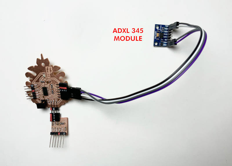
(13/04/2021 17:13 p.m.)Seeing the failure obtained with the LSM6DS33 accelerometer, I have chosen to try to program the board with a different accelerometer module, an Arceli ADXL 345 (Datasheet).
In this case, the pins of this module have a different orientation than the LSM6DS33 accelerometer, so I use some Dupont cables, to connect VCC, GND, SCL and SDA.
Following the instructions on the Adafruit website, the first thing I do is install the Adafruit ADXL345 accelerometer library and I also download the Adafruit Sensor library.
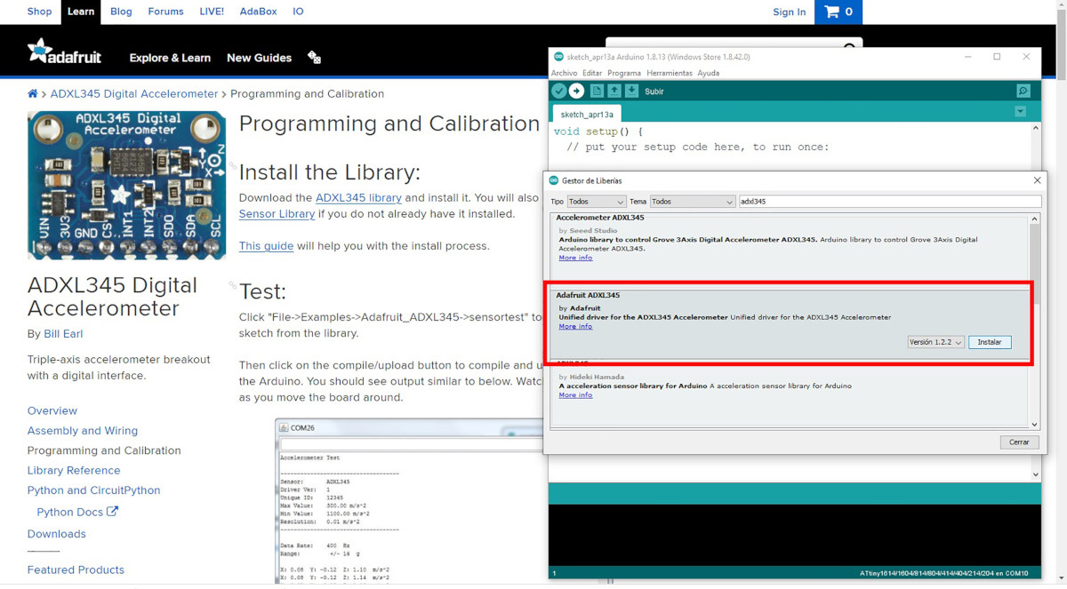
To start with, I try loading the sensortest sample code for this accelerometer.
And when I open the monitor, I see the accelerometer WORKS !!! 🤩🤩🤩🤩🎉🎉🎉🎉
I think this is the first time that something has worked well for me at the first time! 🤣🤣
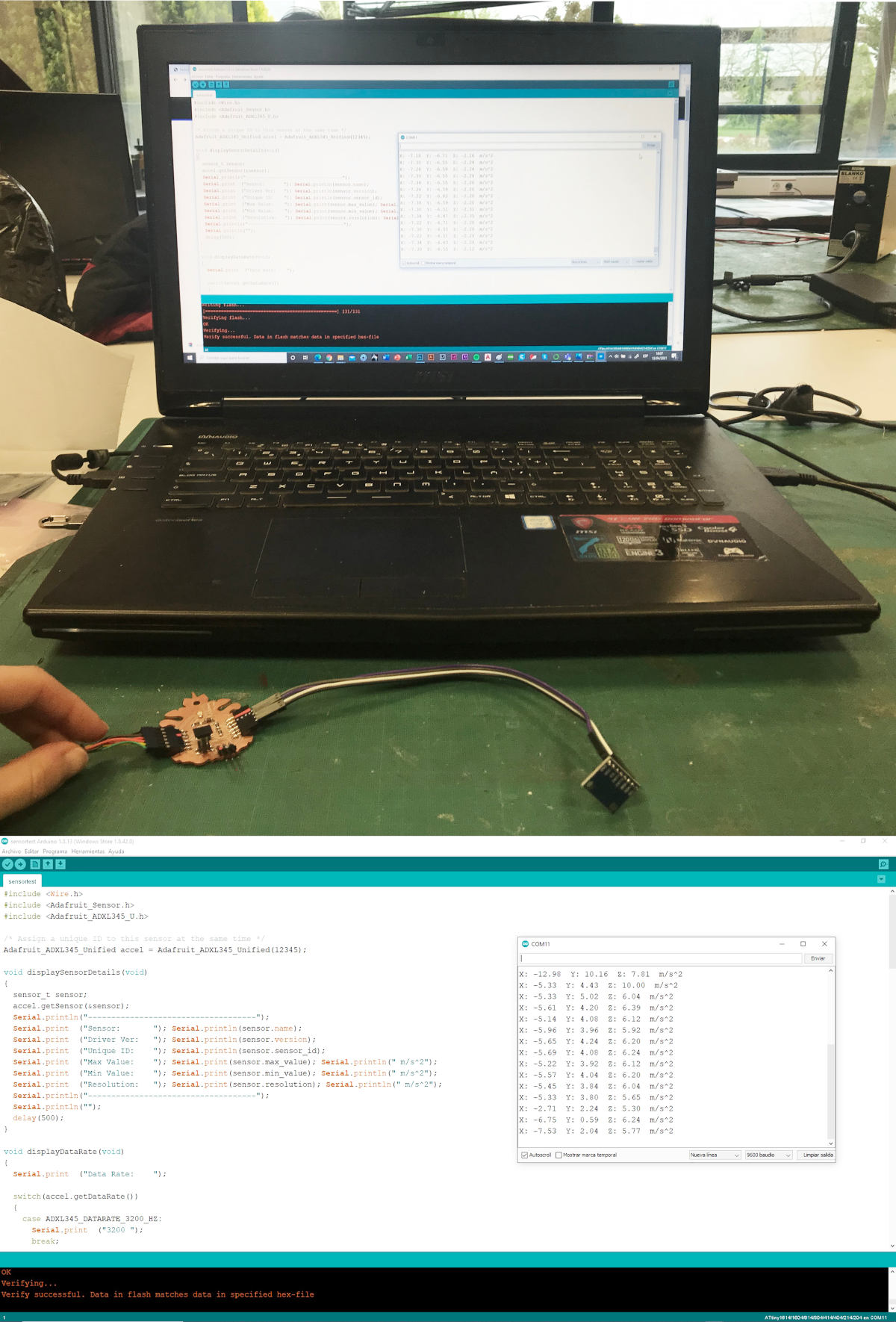
In this video you can see how to move the accelerometer, the monitor is teaching me a series of values in the XYZ axes: 😍😍
-
_ TRY TO PROGRAMMING ACCELEROMETER CODE PART II (POLOLU LSM6DS33 MODULE)
(12/04/2021 22:34 p.m.) During Monday night, Adrián asked me if I managed to solve my problem with the LSM6DS33 accelerometer, before starting to work with the ADXL345. I informed him that I had not succeeded yet 😔. So, he suggested me to try to follow this tutorial for an LSM303 Triple Axis Accelerometer and Magnetometer(Compass)breakout board.
(13/04/2021 18:28 p.m.) So, on Tuesday afternoon, after getting to measure values with the ADXL345 accelerometer 😍, I decided to give other opportunity to the LSM6DS33 module, following the tutorial that Adrián taught me. 😘
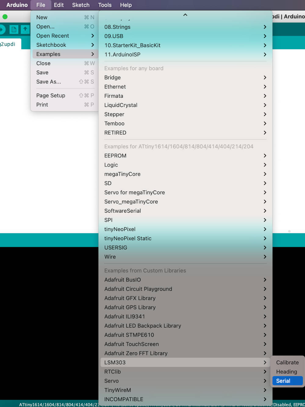
I downloaded the LSM303 library, as well as the Adafruit_Sensor and Adafruit_BusIO libraries. Once I have them, I try to load an example code LSM303 > Serial, and finally I can read data from the accelerometer in the monitor !!! 😍😍😍🎉🎉🎉🎉
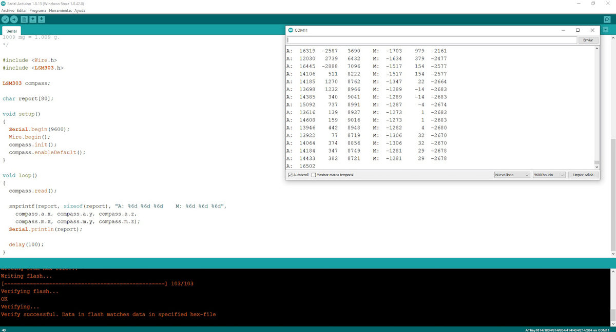
Here you can see a video where according to the movement of my Hello Piña! 3.0 + LSM6DS303 the monitor is reading data from the accelerometer. It is amazing!!!! 🤣🤣🤣🤣
Next, I try a simple code to check the gyroscope, with the code Heading Test. And I verify that the monitor reads the accelerometer again!! 😍😍.
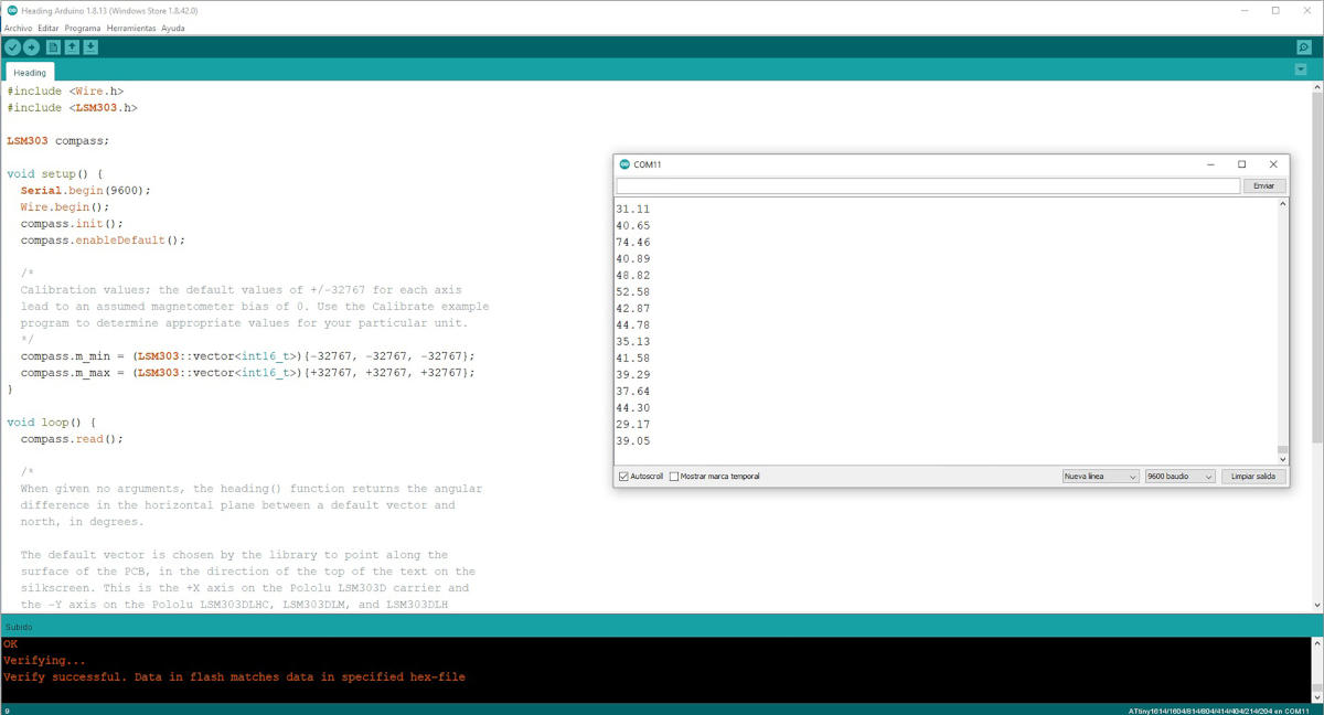
Here you can see a video, where depending on the movement I make, the monitor makes a different reading of data.
SUMMARY
Finally, from a week of ups and downs like a roller coaster, I have managed to program the new Hello Piña! 3.0 with two different accelerometer modules 😍.
After these tests performed, I think I will choose to use the ADXL 345 for my future final project. 😅
FILES
HELLO PIÑA! 3.0 ACCELEROMETER
PROGRAMMING ACCELEROMETER CODE (ARCELI ADXL345 MODULE)
PROGRAMMING ACCELEROMETER CODE (POLOLU LSM6DS33 MODULE)
REFERENCES