
Electronics Design
WEEK 06
(08/03/2021 00:00 a.m.) Monday midnight. Today is International Women's Day, and I want to congratulate each everyone of working women, especially all the women instructors, organizers, women makers, alumni and all my classmates who are part of the Fab Academy program. 💜💜💜
We will continue working and fighting for equality and job recognition. 💪
This week, we are back with Electronics!
Chan, chan, chan (dramatic sound).
But this time, we have entered the unknown world of how to recreate our own PBC boards from design to fabrication.
As it happens to me with electronics, it is a task that is very difficult for me to understand and which I need to dedicate time. (03/03/2021 18:38 p.m.). After our Neil class, I usually feel very exhauted from the pressure and tension of finishing the assignment from the week before. But this time I felt awake and positive 💪💪.
To carry out this assignment, we have needed a lot of help from our instructors Adrián and Nuria. 💚💚
(06/03/2021 09:22 a.m.) And on Saturday, my crewmates Alberto, Sergio and me had the opportunity to meet one alumni from Fab Academy 2019, Alejandro Ulecia, at the Fab Lab UE. Alejandro spent the whole day with us explaining and teaching us, by first hand, his experience at Fab Academy and he was helping us with the components and make our boards.
Despite having been a difficult week, we have continued with the same positive attitude of the weeks before. In honor of this new Monday, the week song is No light, No light by Florence + The Machine.
(No light)
Tell me what you want me to say 🙆♀️
Organizing tasks
Since week 04 we have two types of assignments, one's group and other individual. So as usual, I organize my schedule and here the following Evaluation Criteria that we have to approach to complete the Assignment:
- ✓ Use the test equipment in your lab to observe the operation of a microcontroller circuit board (check operating voltage on the board with multimeter or voltmeter and use oscilloscope to check noise of operating voltage and interpret a data signal, minimum)
- ✓ Document our work with the test equipment
- ✓ Redraw one of the echo hello-world boards or something equivalent
- ✓ Add (at least) a button and a LED (with current-limiting resistor) or equivalent input and output
- ✓ Check design rules, milling, soldering it and test it
- ✓ Included our original design files (Eagle, KiCad, etc)
- ✓ Documented what you have learned and explained the problems we had, how to fixed them, if the board doesn´t work, etc
Extra credit
- ✓ Include a "hero shot" of our board
Group Assignment
MULTIMETER
At Fab Lab IED Madrid we use a multimeter from Unit-T UT139C brand, which we use in design and innovation masters, specifically electronics subjects.
In my case, I use the multimeter to check the direction and polarity of some components such as LEDs or diodes, in addition to checking the continuity of the tracks on the boards that we mill.
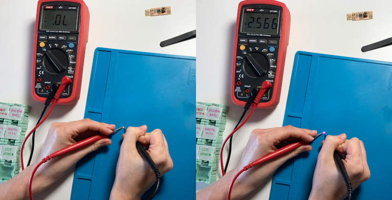
In this short video you can see how I verify the polarity of the LEDs. On LEDs, a green mark usually appears on one side, indicating the negative pole of the component. To verify the polarity of the LEDs, we must place the black test lead (GND) with the LED´s negative pole and the red test lead (current) with the LED´s positive pole.
Here you can see how I verify the continuity tracks of the FabISP I did at Week 04:
Individual Assignment
FIRST "HELLO BOARD" PROTOTYPE
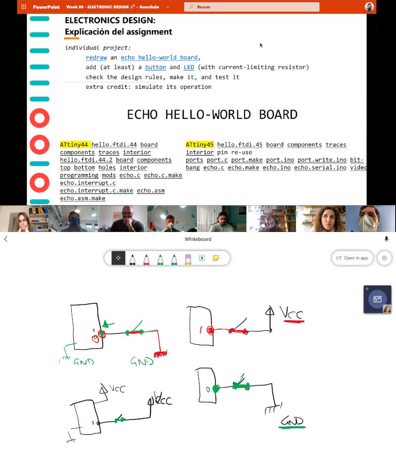
(04/03/2021 10:24 a.m.) Thursday morning.. After Neil's class, at the local review we do a review with Adrián + Nuria + Pablo, about the objectives that we must approach for this week.
Among the five crewmates that belong to the Fab Lab León, for the majority of us, designing boards is something completely new because we do not know or have forgotten some basic concepts about components, electronics and circuits since our high school studies 😅. That is why we review how works the operation of microcontrollers when we connect them to VCC or GND, among others.
As we do not have much experience in boards design and microcontrollers, Nuria recommends us to work on spirals, starting with easier microcontrollers and then trying to level up using the new generations of microcontrollers.
So as a first spiral, I take Nuria's recommendation to work with the Echo hello-world ATtiny45 board .
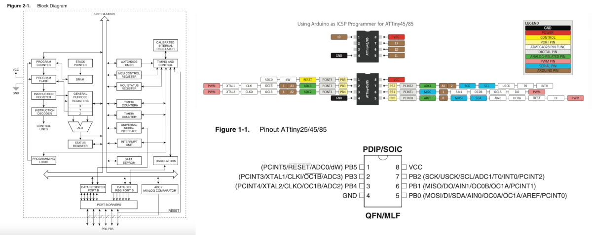
The first thing I do is look for the ATtiny 45 Datasheet to familiarize myself with the type of microcontroller I am going to work with and the pins that compose it.
I do not fully understand the operation of the microcontrollers and their datasheet yet, but little by little I am seeing how the pins work and how I have to connect them with the rest of hello-world components.
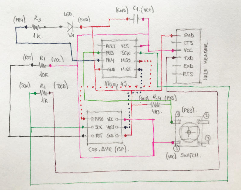
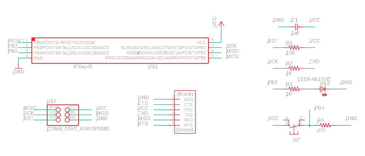
As we have to make a board where we include (at least) a button and a led, following the scheme of the hello.ftdi.45, I draw, schematically, the components that I am going to use and with colors I draw the paths that connect some pins and components with the others.
- EAGLE
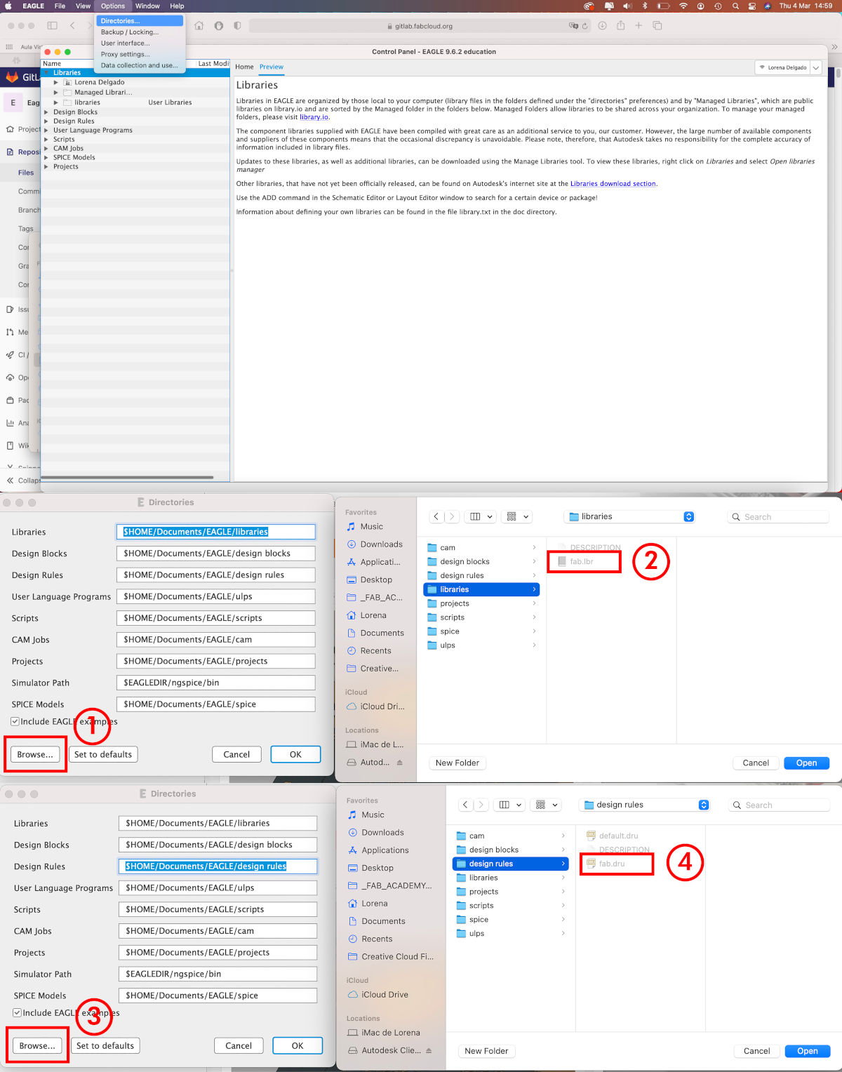
To design my first hello-world board, I used EAGLE version 9.6.2. Following Nuria´s instructions during our local Review, the first thing we do is download and install the fab libraries and design rules that Neil taught us during the class. Here you can download the libraries.
To install them we have to go to: Options > Directories. From Downloads we copy the fab.lbr file. We opened Eagle´sDirectories window, and in Libraries we select the directory and click on Browse ... It will go us to an Eagle library folder, and here we paste the fab.lbr file.
To install the Design Rules, we do the same process, but following the Design Rules route in the directories.
Following Nuria´s video tutorials 💚 that she did for us about Eagle Introduction, I started adding and wiring between the components I need for my hello-world.
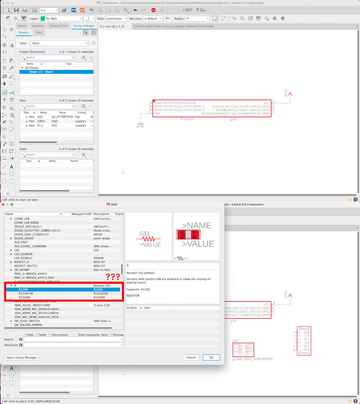
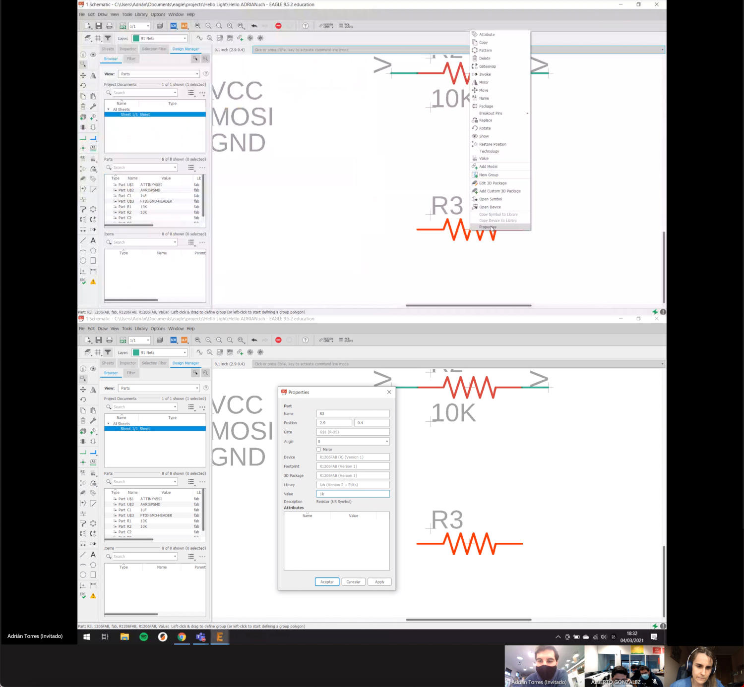
Here Adrián came to my rescue! 💚 During our meeting, in which Alberto joined us, Adrián told us, that in this case, the type of resistance we should use were the "Fab" tags components. He selected the R1206FAB resistance. When he placed it on the board, he told us to change the name and load of the components, we should Click Right on the component > Properties, and in Value we can put the load value in the resistance we will use.
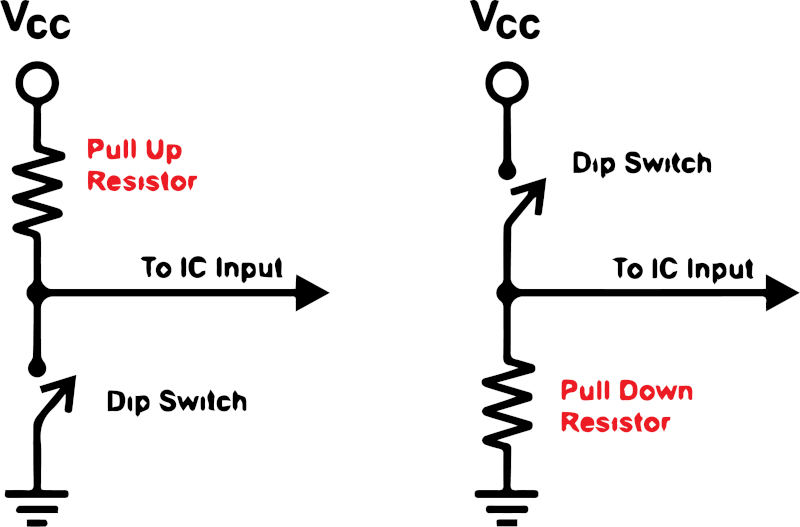
When I get to the button part, during the local Review, Nuria explained us that there are two ways to place it: using a pull-up or pull-down resistor. This means that when the button is open the load can enter into the microcontroller pin, to which we connect it, and vary the status of your entry.
If we put a pull-up resistor, we will be connecting the button to GND (ground), while if we put a pull-down resistor, the button will be connected to VCC.
Once I have place, connected and identified all the components and their pins, I generate the board and go to the Switch to Board tab.
In the Board view we started moving, rotating and wiring the tracks that connect the pins of our hello-board.
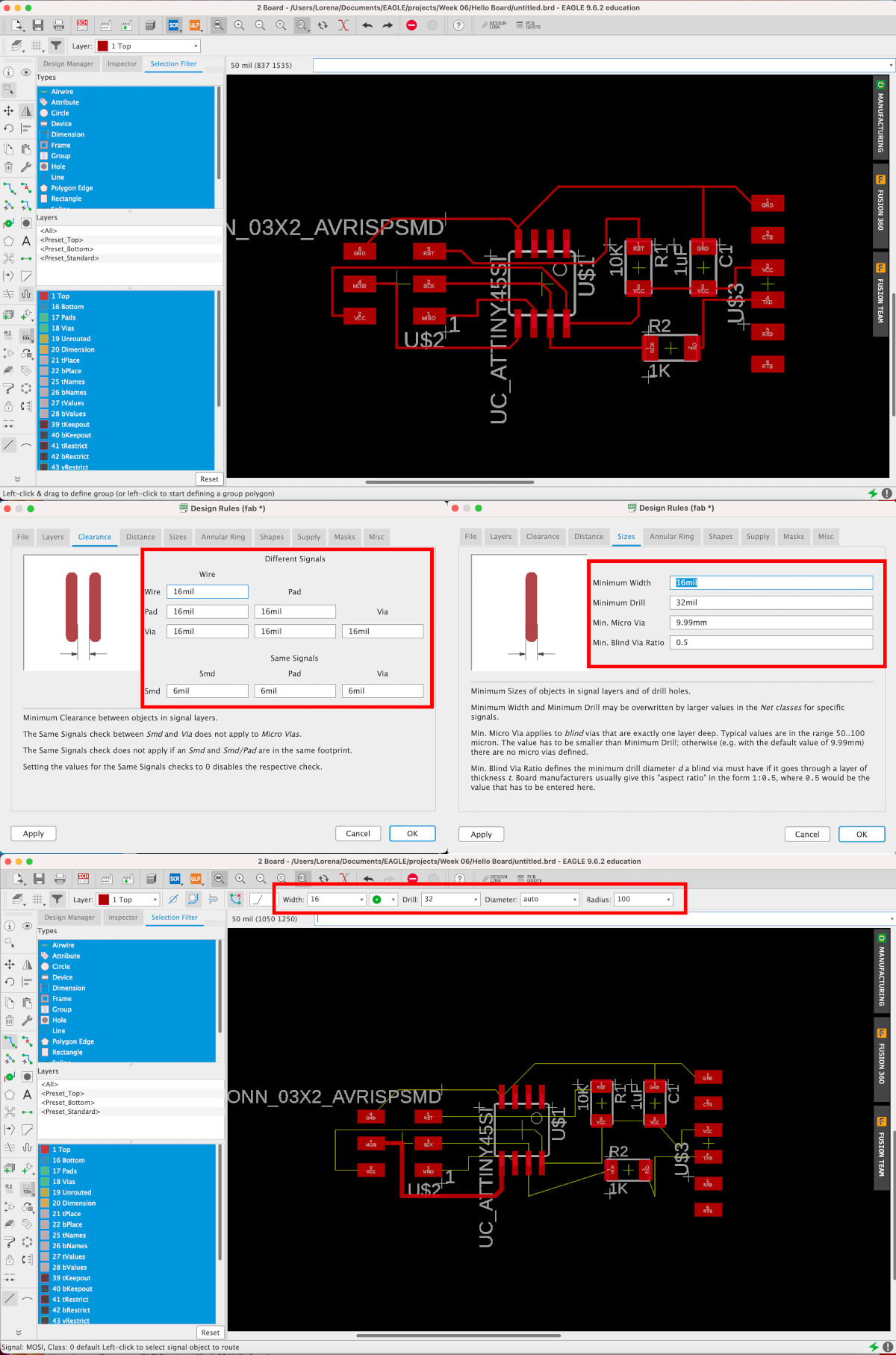
While I was wiring I did not realize that the tracks I was drawing were from 6 mil width, and Adrián reminded me that I should activate the fab Design Rules and put them with a measure of 16 mil width.
For this, we go to Edit > Design Rules ... On the first tab, let's go to Load ... and we select the fab.dru file, we have previously installed. Here we have to verify the Clearance and the Sizes have the measurements showing in the image below.
(06/03/2021 11:27 a.m.). After several attempts to design, I decide to start with this type of board.
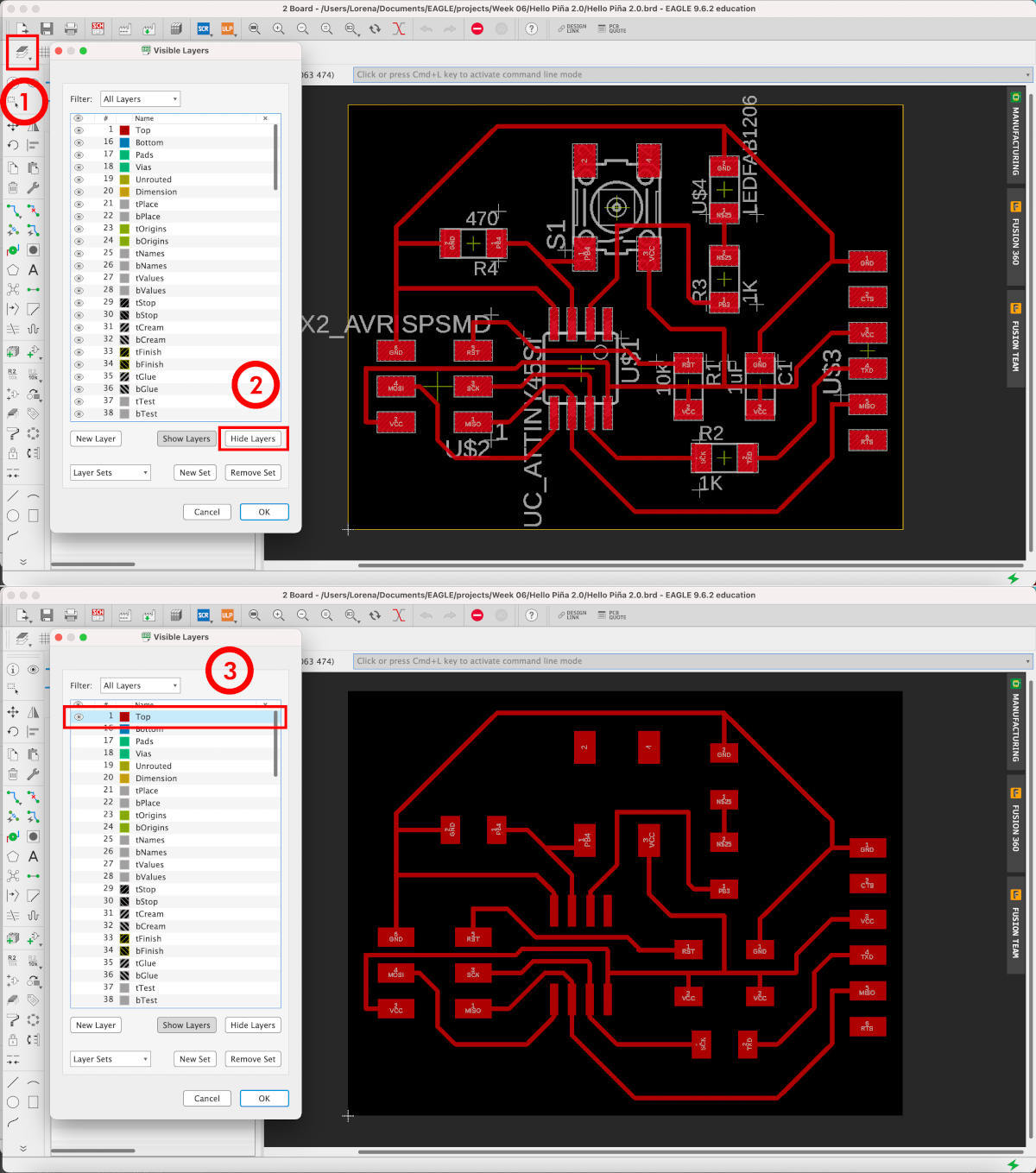
Now, we must hide all the layers except the top layer, in which our tracks and the trace of our components are drawn.
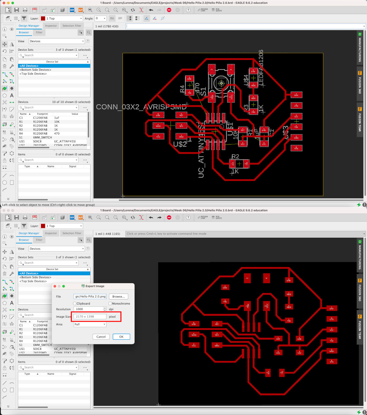
Once we have it ready, we export the diagram to .png in: File> Export> Image. And here, we select the location where we want to export the image to 1000 dpi of resolution, in Monochrome and Full Area.
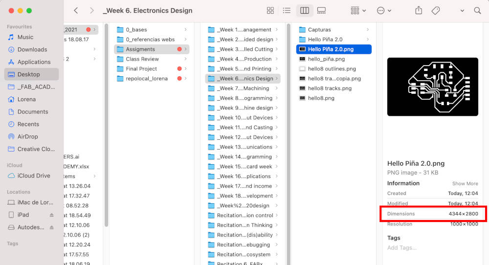
An error that appears by default when exporting the Eagle´s png files on Mac is, when we set the image the dimensions are duplicated 😳. Nuria told me this error is quite common because Mac understands the exported image is in inches and to transform it into pixels per mm duplicates the images x 2.54.
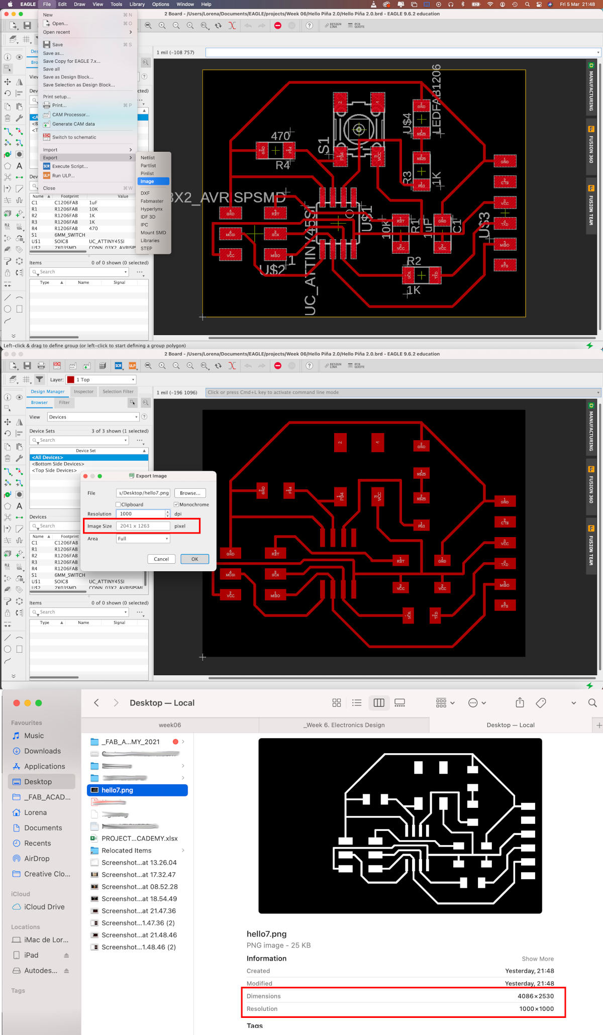
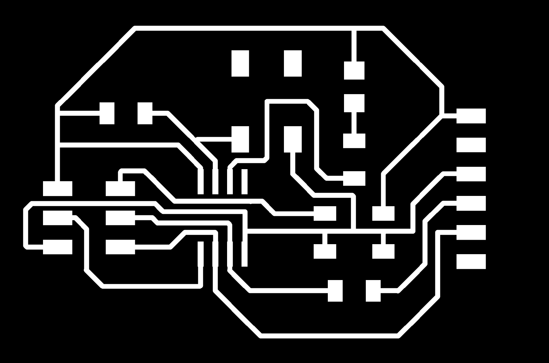
So, every time I export an image from Eagle, I have to scale the measurements of the image from Illustrator or GIMP 😅😅. Here, you can download the First Hello Board Traces.PNG + First Hello Board Outlines.PNG
- MILLING FIRST BOARD
To mill my first Hello-Board, Alberto uses at the FAB Lab UE Fab Modules, so I prepare the files and load the milling board on his Roland MDX-40.
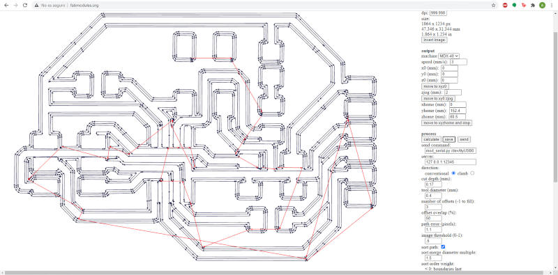
Here you can watch a short video where I am milling the tracks of my first board:
(06/03/2021 18:09 p.m.). While the machine was milling the outlines of my first borad, the Roland MDX-40 decided not to work, mysteriously. 😳
So Alejandro suggested me to do something that anyone should NOT BE DONE, but ... as the Spanish saying goes: "A grandes males, grandes remedios". (The translation in English is something like: Huge evils things, great remedies solutions). 🤣🤣🤣
Alejandro helped me cut my first hello-world with a cutter and a saw. 🙊🙊
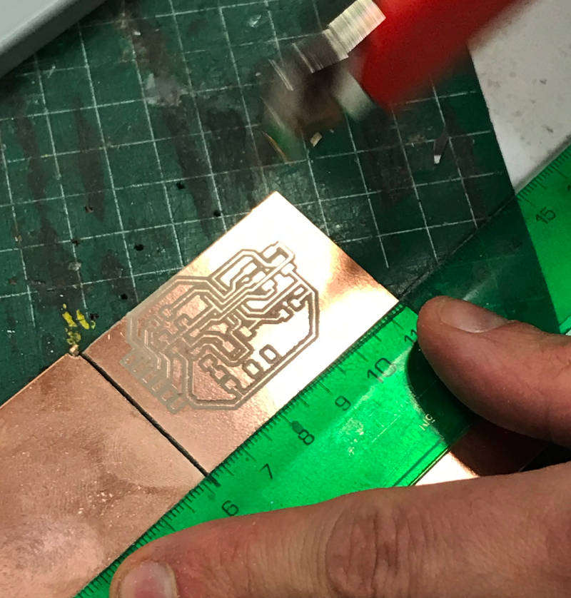
I know I know! This is not politically correct showing it, but...
Does not Fab Academy consist of explaining and showing our experience, both the good and bad side of what we do during the assignments?
- SOLDERING FIRST BOARD
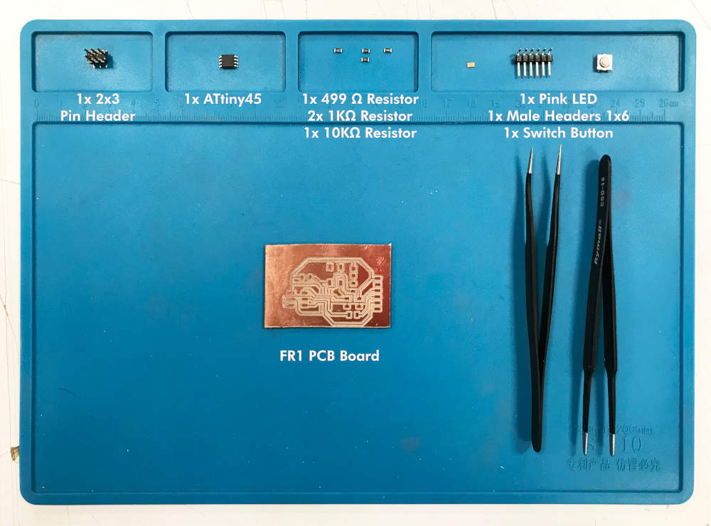
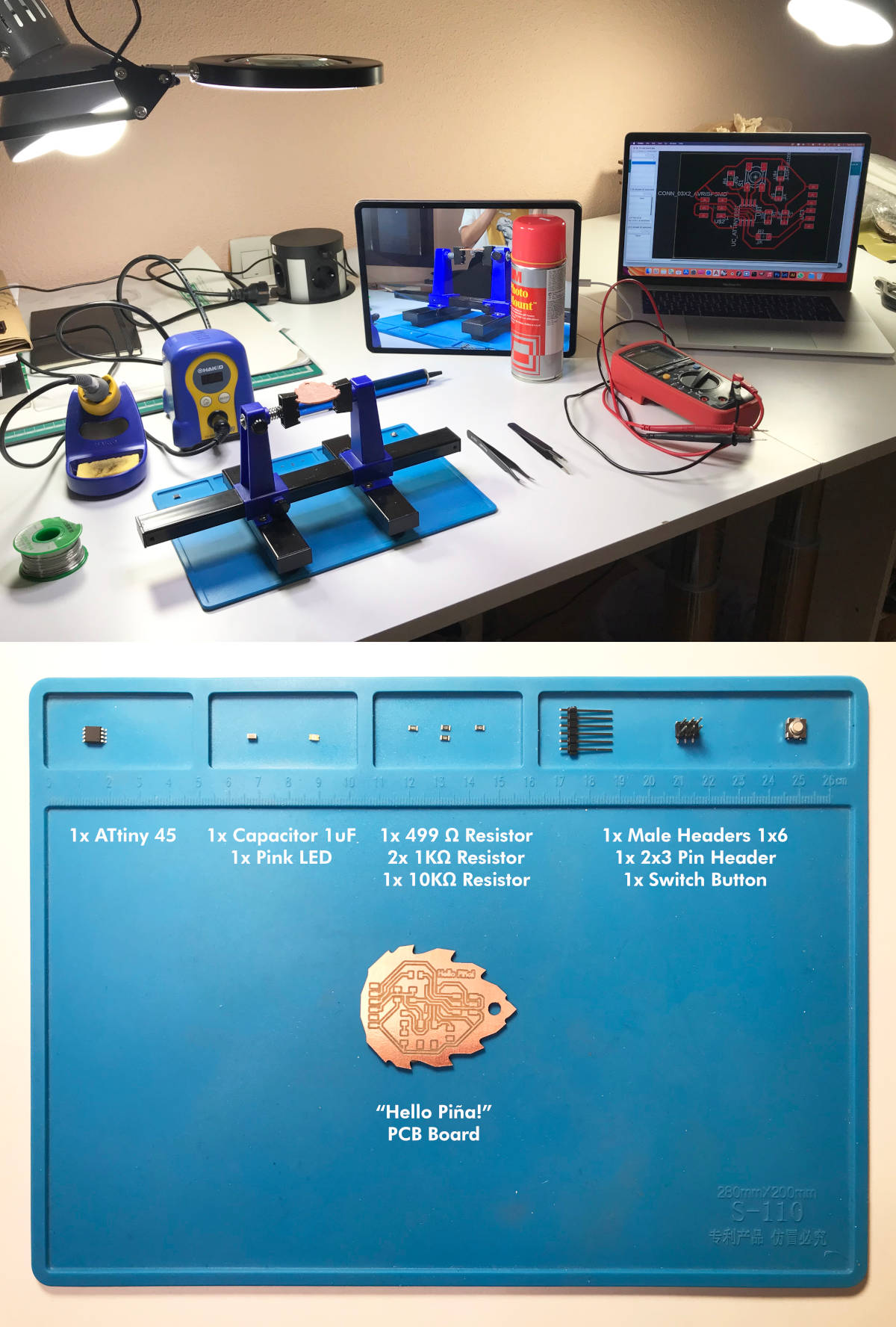
(06/03/2021 18:23 p.m.). Once, Alejandro helped me to cut the board, I prepared the components I needed to weld my first Hello-Board:
- 1x ATtiny45
- 1x 10kΩ resistors
- 2x 1kΩ resistors
- 1x 499Ω resistors
- 1x 1uF Capacitor
- 1x pink LED
- 1x Switch Button
- 1x 1x6 male header
- 1x 2x3 pin header
(06/03/2021 19:04 p.m.).Once I started soldering, Alberto made a video that sent our instructors. Adrián intercepted a series of problems while I was welding (and that I will not to commit). 😅😅
First is, I have to begin soldering the smallest components, and leave the bigger ones for the end.In my case, I made it upside down 🙃.
The other issue was the FTDI male pins that I used had the pins folded in perpendicular and could give me problems and breaking the tracks. (Thing that happened to me). 😬😑
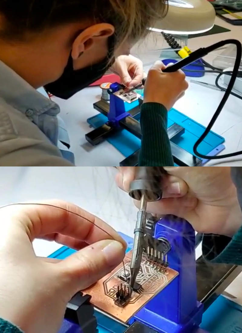
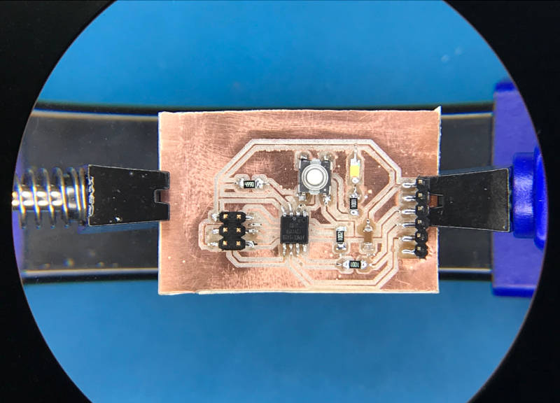
Despite the faults committed, I managed to weld the whole board! And this was the final result!
- TRYING TO PROGRAMMING
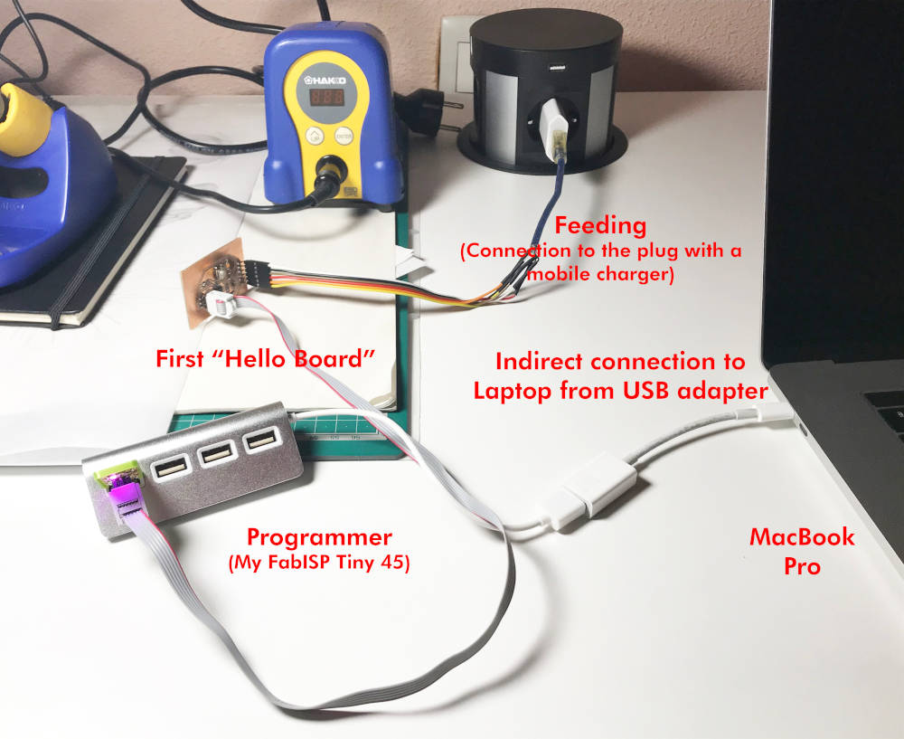
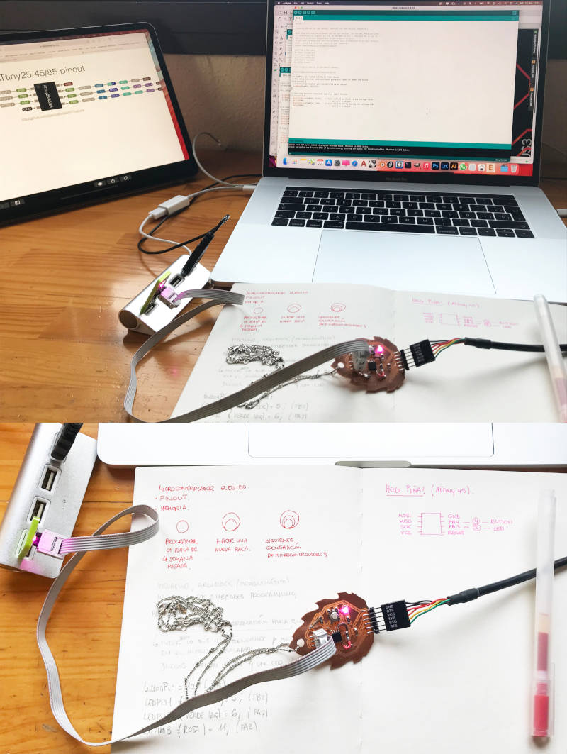
For this, what I did was to follow the same procedure as in Week 04. First, indirectly plug my programmer with a USB adapter to my laptop. With the flat cable connect my FABISP Tiny45 with the ISP header of my Hello Board, and with a FTDI cable connect my Hello Board to the current through a mobile charger.
I open the Arduino version that had installed since last year, and I updated to version 1.8.13.
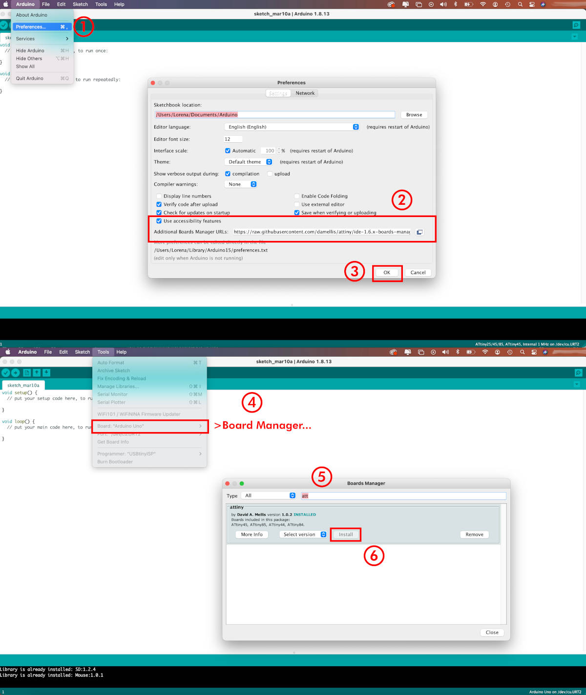
Following the steps of this tutorial of How to program a Hello Board Attiny45 with a FABISP, I go to Preferences, and in Additional Boards Manager, I add this URL.
Once added, I go to Board Manager, search for "attiny" and download David Mellis version 1.0.2.
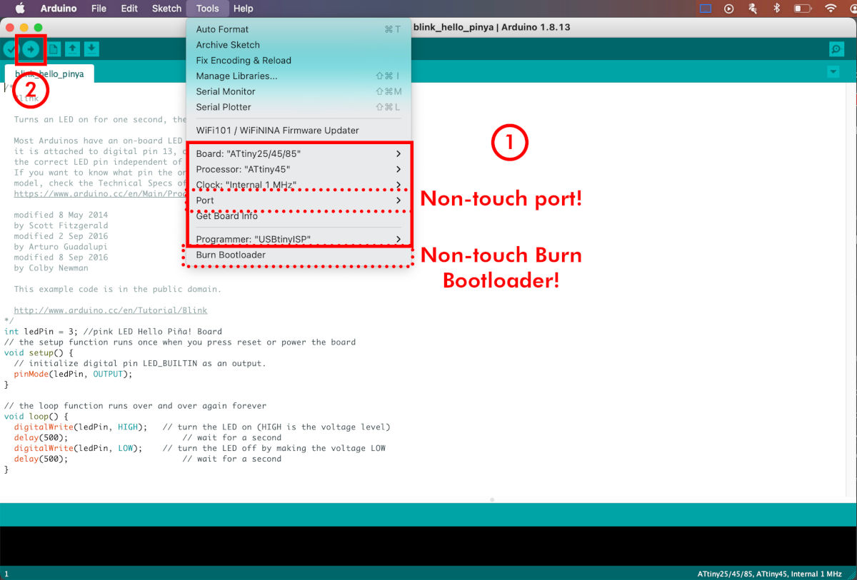
Program a simple Blink code, and in Tools, adjust the following features:
- Board: ATtiny25/45/85
- Processor: ATtiny45
- Clock: Internal 1MHz
- Programmer: USBtinyISP
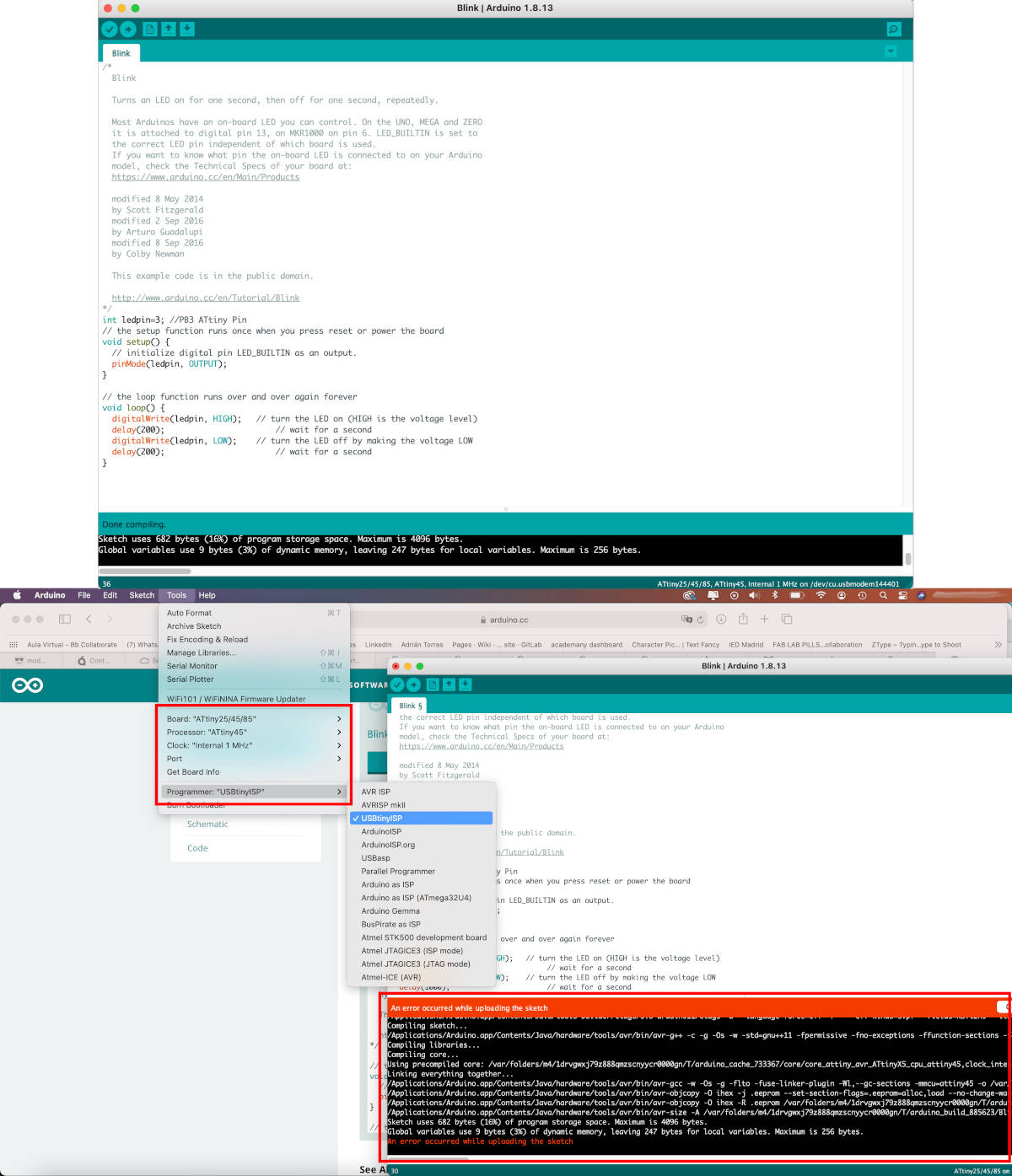
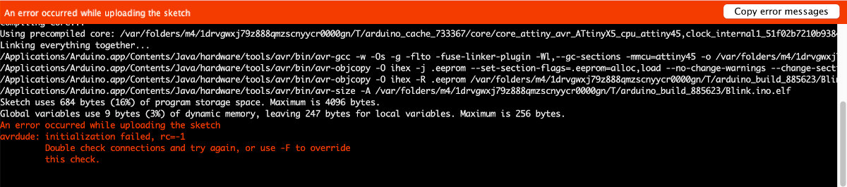
But something strange happens! 🧐 The first thing that appears when the programming my board is: An error occurred while uploading the sketch.
When I try to reload the file, a new message appears:
avrdude: initialization failed, rc = -1.
How is it possible?🙇
(06/03/2021 23:13 p.m.) Faced with this problem, and being still Saturday, I decide to venture myself to design another new Hello-Board during next Sunday a little more decent. 😂💪
"HELLO PIÑA!" BOARD
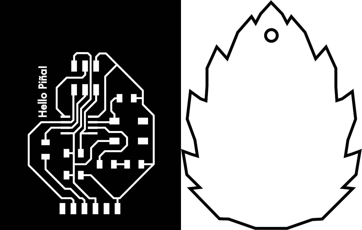
- REDESIGN A NEW TRACES CIRCUIT
(07/03/2021 08:19 a.m.). During Sunday morning, I began to redesign my new Hello-World board.
To do something fun, and honor my second last name, which is Piña (Piña in Spanish has double meaning: can be pineapple or pine cone), I came up with the idea of making a pine cone shaped board, and baptizing it as Hello Piña! 🤣🤗.
So following the same steps I realized in my first Hello-World, I reorganized the components of my hello-world Attiny45. And when I exported the image of the traces, I had to re-adjust the image dimensions manually by the conversion issue of inches to mm.
TFor the outlines of the pine cone, I looked for an image that I liked and redrawn its outline in Illustrator.
Once drawn, I adapted the outline´s size to the size of the image of the board tracks. I customized and added a small detail to make the board hang up 🤓.
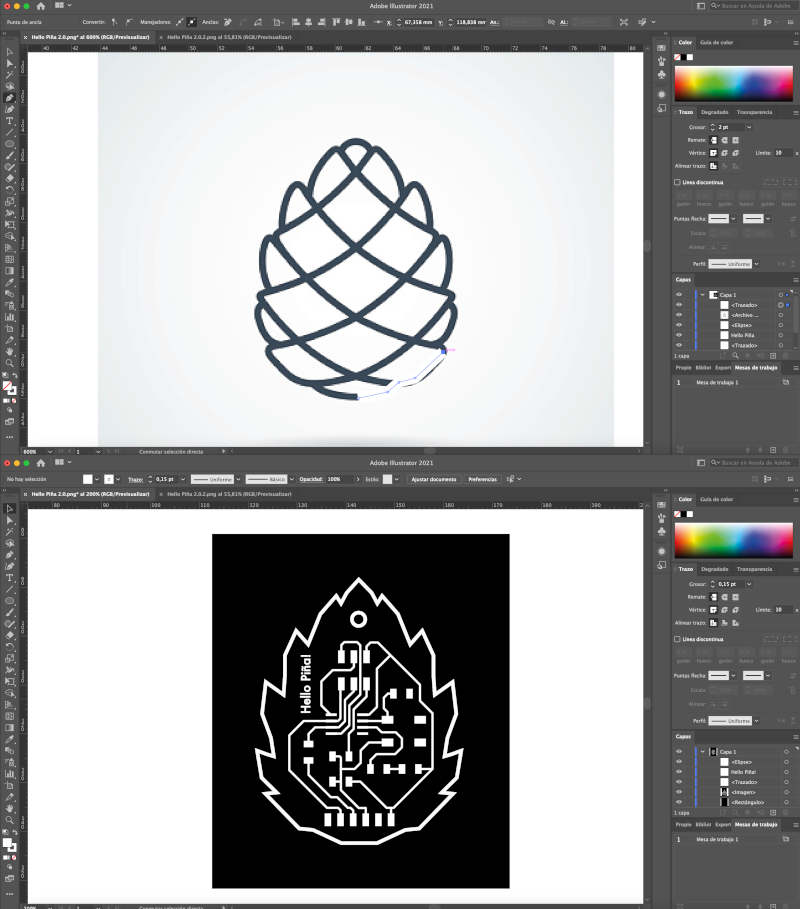
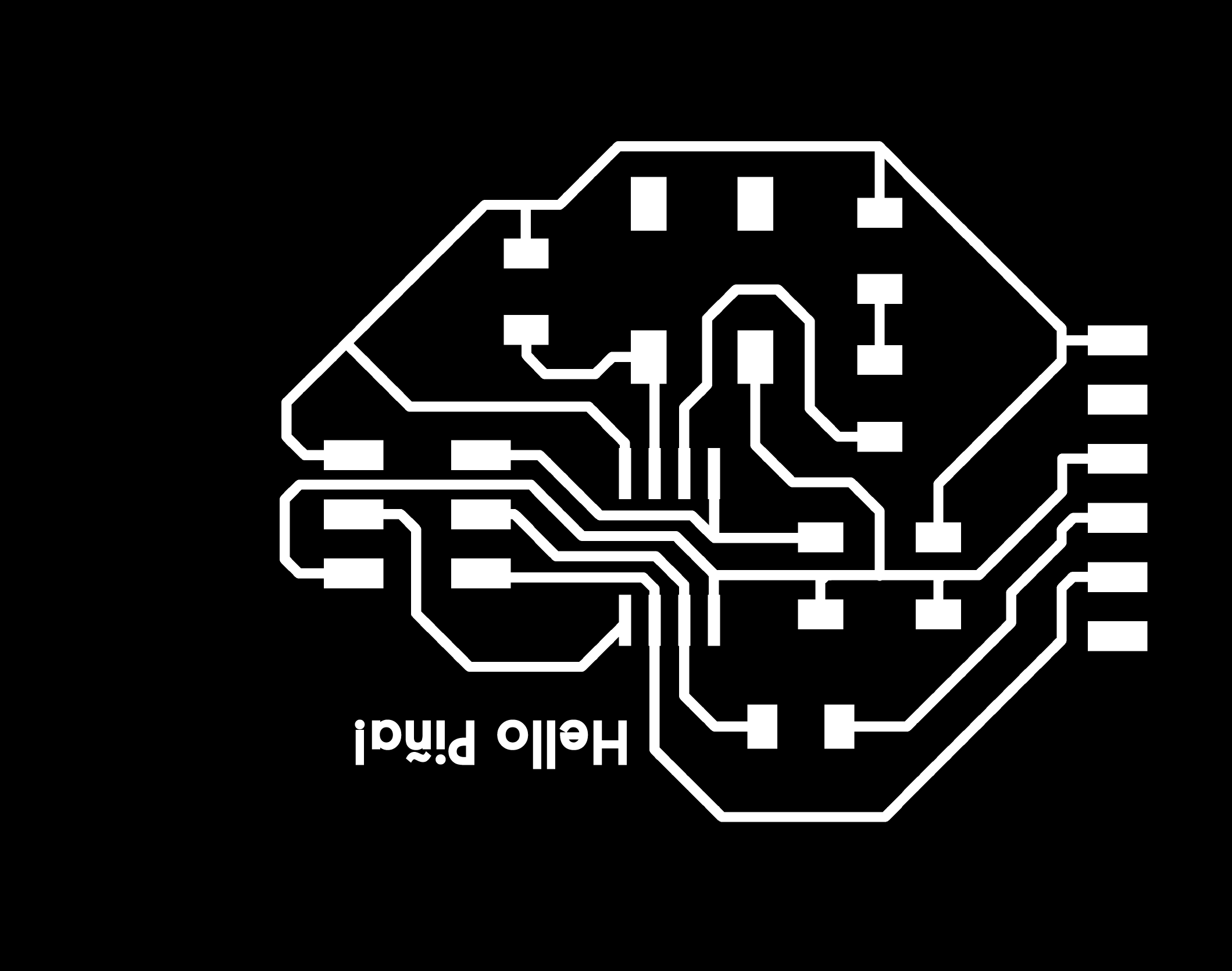
This is the final result of my first Hello Piña!😍. Here you can download the Hello Piña Traces.PNG + Hello Piña Outlines.PNG files.
- MILLING "HELLO PIÑA!" BOARD
(08/03/2021 09:03 a.m) Happy International Women´s Day!💜💜, In Madrid, for several years, this day is usually a very nice day!. But unfortunately due to the COVID-19 situation it has not been possible to celebrate. 😢 However, we will continue working and fighting for the rights of working women 💪💪.
As I have introduced in previous weeks (and you have seen throughout this assignment) when I talk about my thoughts and feelings I write in orange, and when I make mistakes I write them in purple.
(08/03/2021 17:04 p.m) I would have liked during this day, everything I did was written in orange. But unfortunately, the morning and part of the afternoon of this day I made many mistakes and unexpected. 😓😓😓
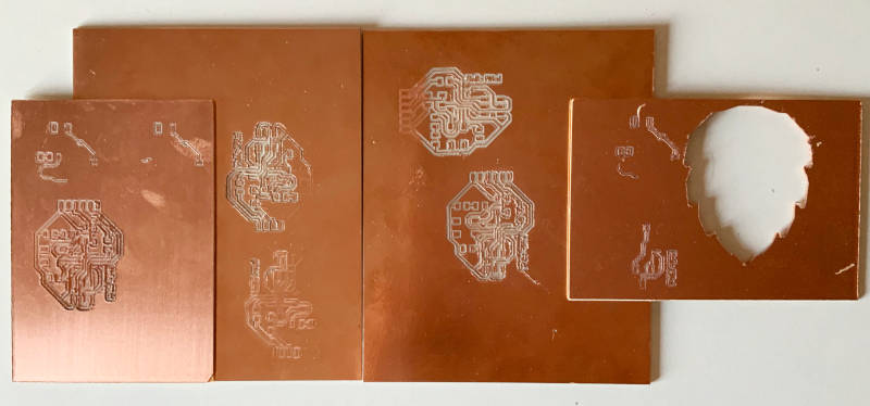
(08/03/2021 09:08 a.m) First thing in the morning, I started milling my first Hello Piña! The problem was when I was milling the first one I did not realize that the bed of the milling machine was out of calibration. That meant, in the following attempts I had to change the direction of the board and I had numerous errors...😥
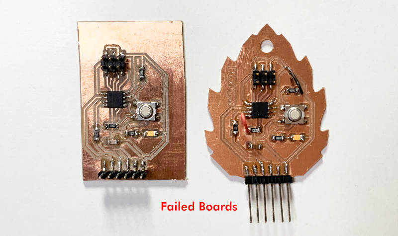
(08/03/2021 18:56 p.m) These were all the mistakes I made and all the material I wasted to be able to mill my first Hello Piña! 😨😨😭😭
I know, I know! Again, this is not properly to showing. But for beginners like me, it is important to show the dos and don'ts to learn in the future.
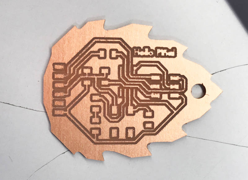
(08/03/2021 17:17 p.m) Despite all the mishaps, I finally managed to mill my first Hello Piña! 😍😍😍
- SOLDERING "HELLO PIÑA!" BOARD
(09/03/2021 07:12 a.m). Tuesday morning. I get up early to try to solder the board components first before the Regional Review. I prepare all the material and again I use the components that I made in my first hello-world board hello-world board.
I reported my problem to my instructors and Nuria suggested me to have the tracks wired like a Frankenstein with cables that I had at home.
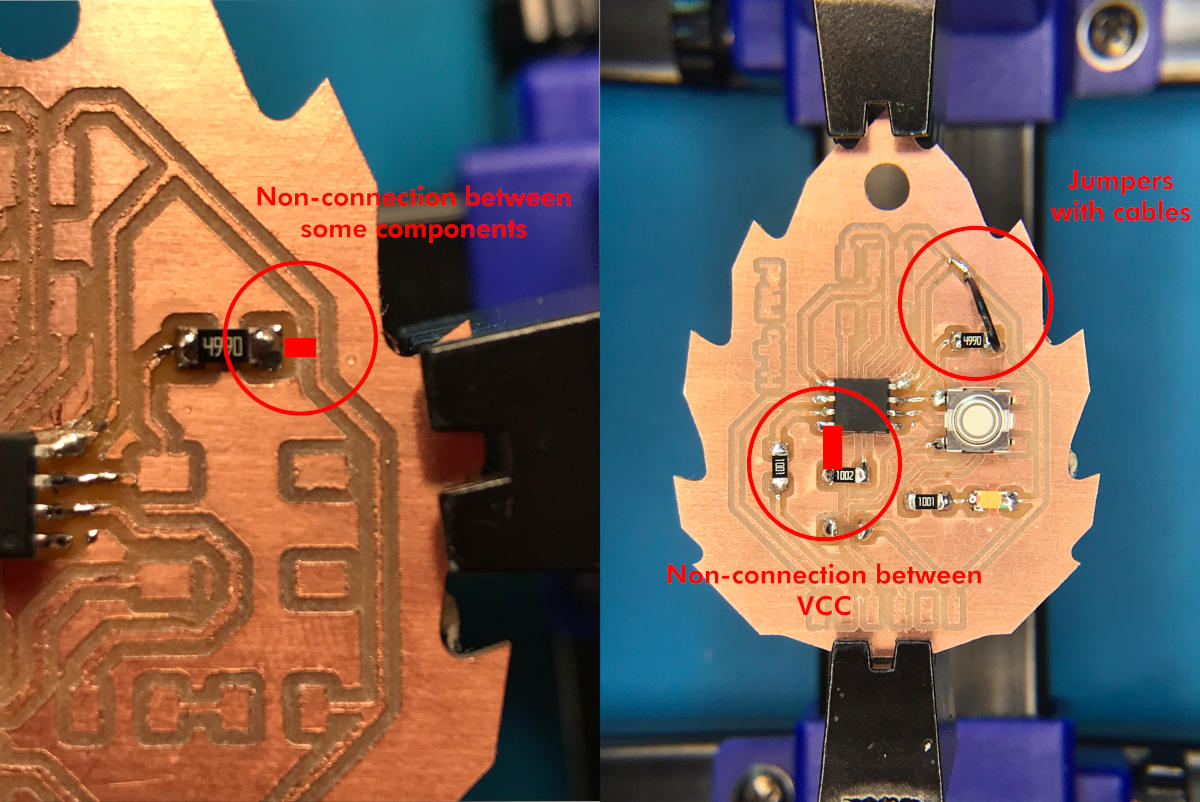
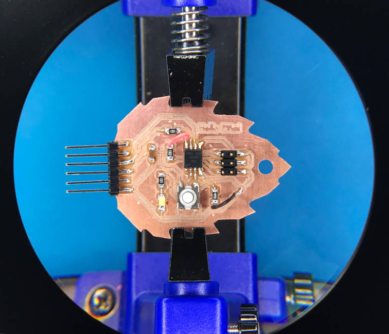
After soldering and wiring the tracks that I had not milled, this was the result of my franken Hello Piña! 🧟♀️🤣😍.
- TRYING TO PROGRAMMING (PART I)
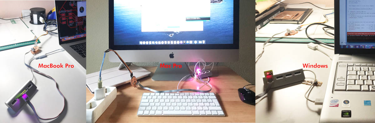
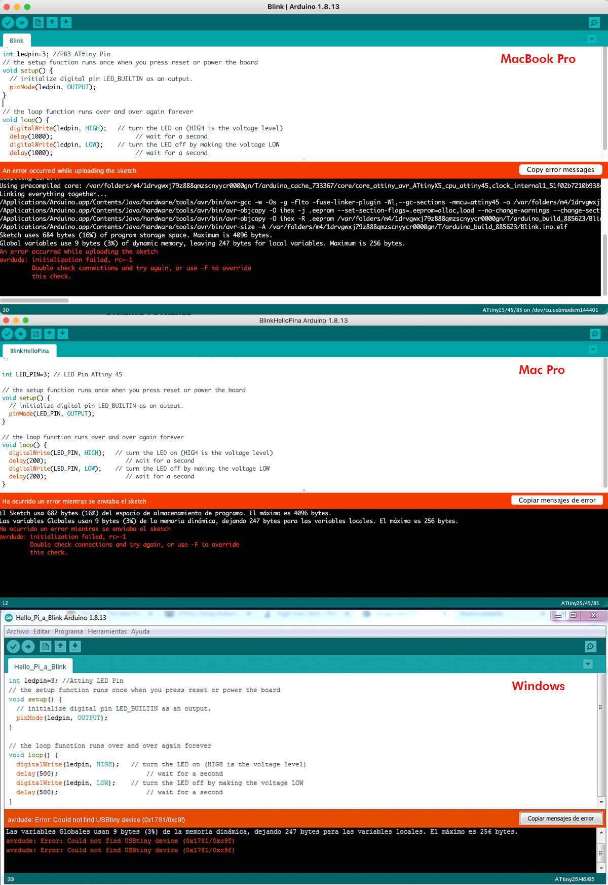
I tested it on three different kinds of computers that I had at home, following the same procedure on each of them, testing different USB ports, different versions of Arduino ...
But sadly a message was repeated, over, over again ... and over again...
avrdude: initialization failed, rc = -1.
avrdude: initialization failed, rc = -1.
avrdude: initialization failed, rc = -1.
...
😭😭😭😭😭😭😭😭
Did I have a problem with welding again? How is it possible?
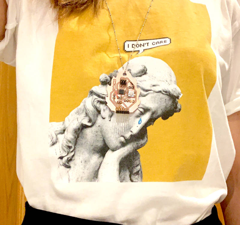
The only positive consolation in this story was what I learned, get humor out of the matter (using my Hello Piña! as a pendant) and settle the problem a few days later, when I will be calmer. 🧘♀️
- TRYING TO PROGRAMMING (PART II)
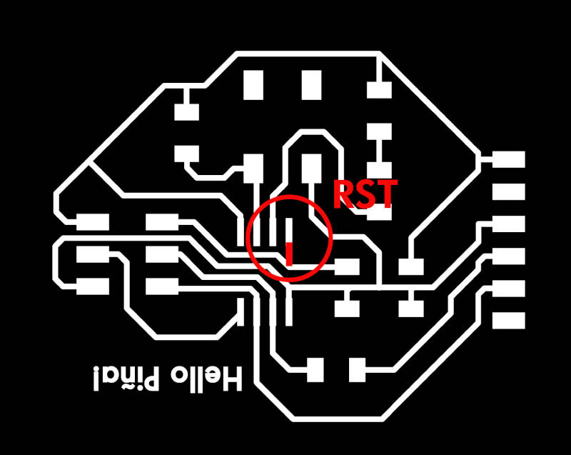
(12.03.2021 9:29 a.m.) After a few days of rest, while we were working at Week 07 with the CNC machine, I began to review the design of my board to see if the error could come from here.
When I started to review it and seeing the work that my crewmates had done and compare with mine, I realized that I had not connected the ATtiny RST pin with the ISP of my board. 🙇🙇🙇
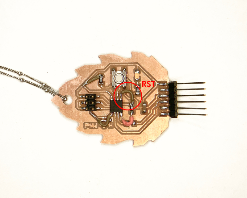
So I had to wire the ATtiny RST pin with the track that connected the resistor with the RST pin of my ISP Header. At the end my board looked like a Frankenstein as my Frankenmannequin from Week 07. 🤣🤣
(21.03.2021 20:23 p.m.) During this weekend, Nuria 💜 replied my Hello Piña! and it worked! 😱 So following the same workflow that she did on Arduino ...
HELLO PIÑA! IS RISEN !!!!!!
😭😭😭😭🎉🎉🎉🎉🎉🎉
Thanks so much for the help, Nuria! 😍😘💜
(To watch the entire process of How we fix my Hello Piña!, you can see it at Week 08).
Here you can see a short video using an Arduino Blink Example :
And, here you can see other short video using an Arduino Button Example :
REFERENCES
OSCILOSCOPE AND MULTIMETER
EAGLE
FILES
FIRST "HELLO BOARD" PROTOTYPE
HELLO PIÑA!