BACK TO HOME PAGE
FINAL PROJECT
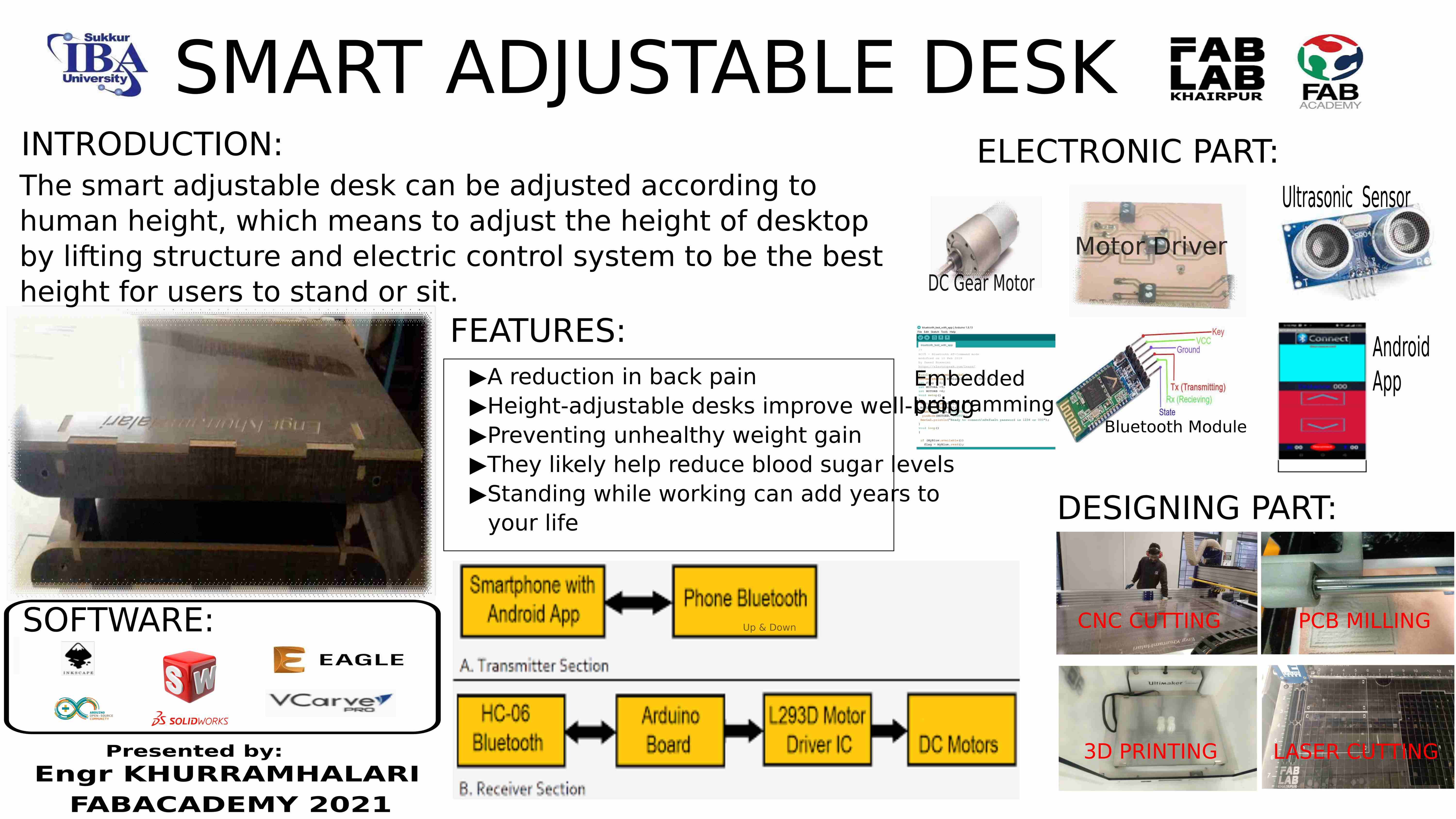
SMART ADJUSTABLE DESK
Final Project Slide
Final Video
Mechanical Designing
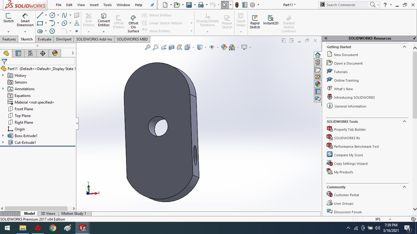
I used a professional approach for the mechanical design and first decided to make a CAD. I used solid works for this purpose because it is one of the most advanced software available for CAD. After designing I used shopbot to cut parts for my project precisely this helps me a lot in calculation and due to this hardware designing become simple for me.
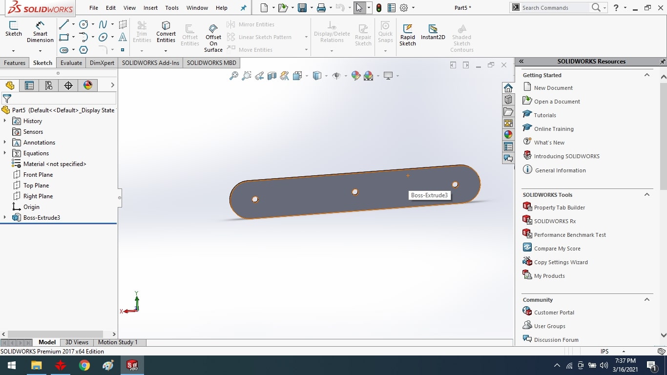
Designing of Main Body
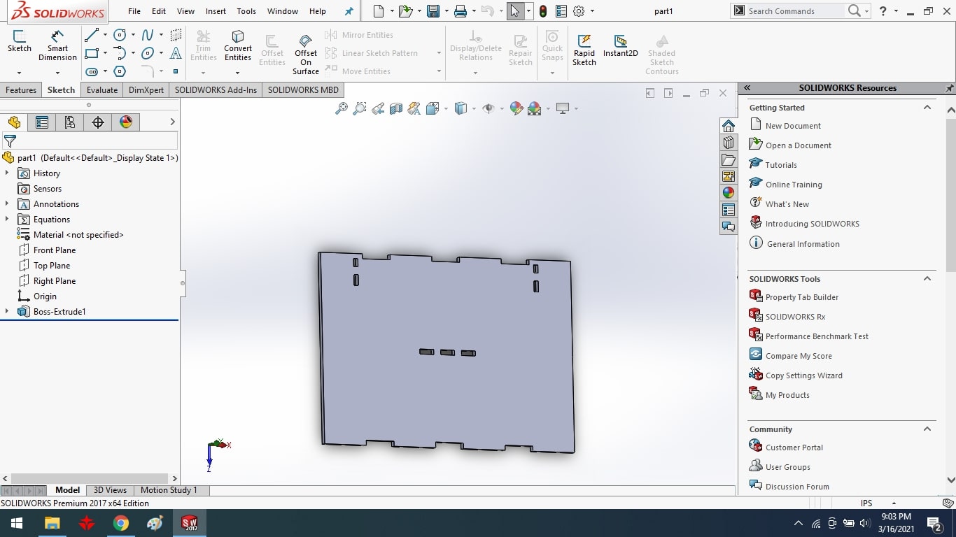
Bottom Part of Desk
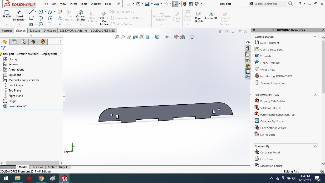
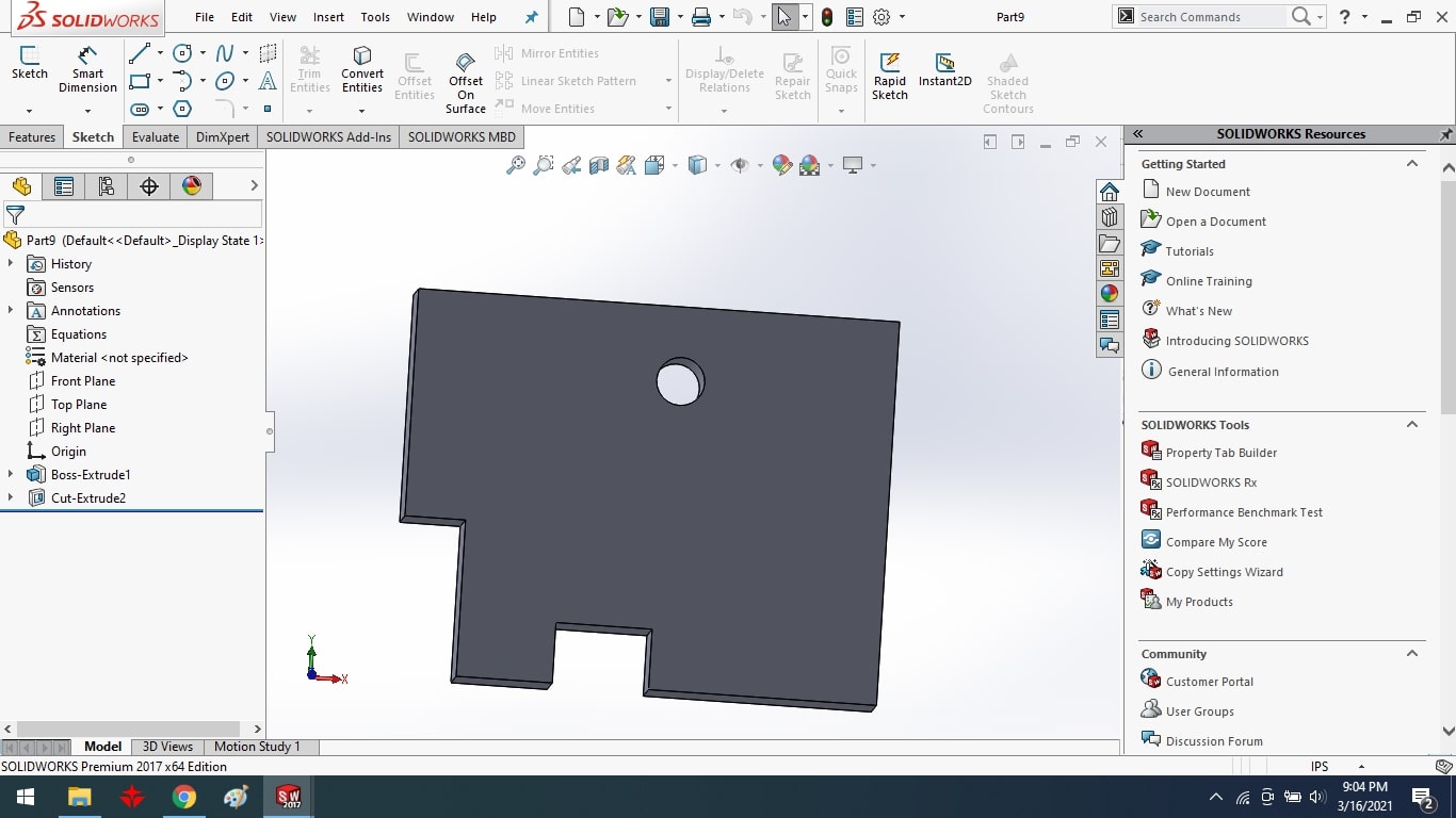
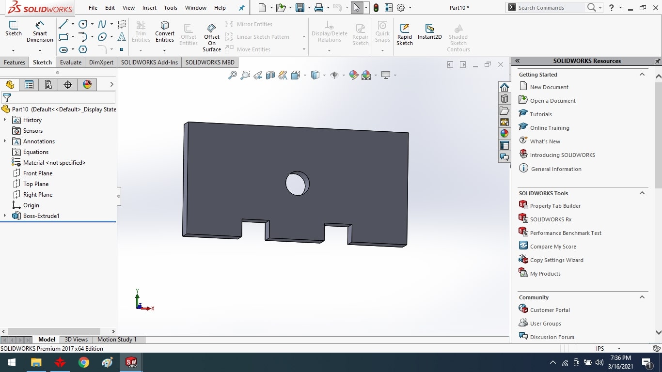
Bottom Side Support Part.
Scissor Support.
Scissor of Desk
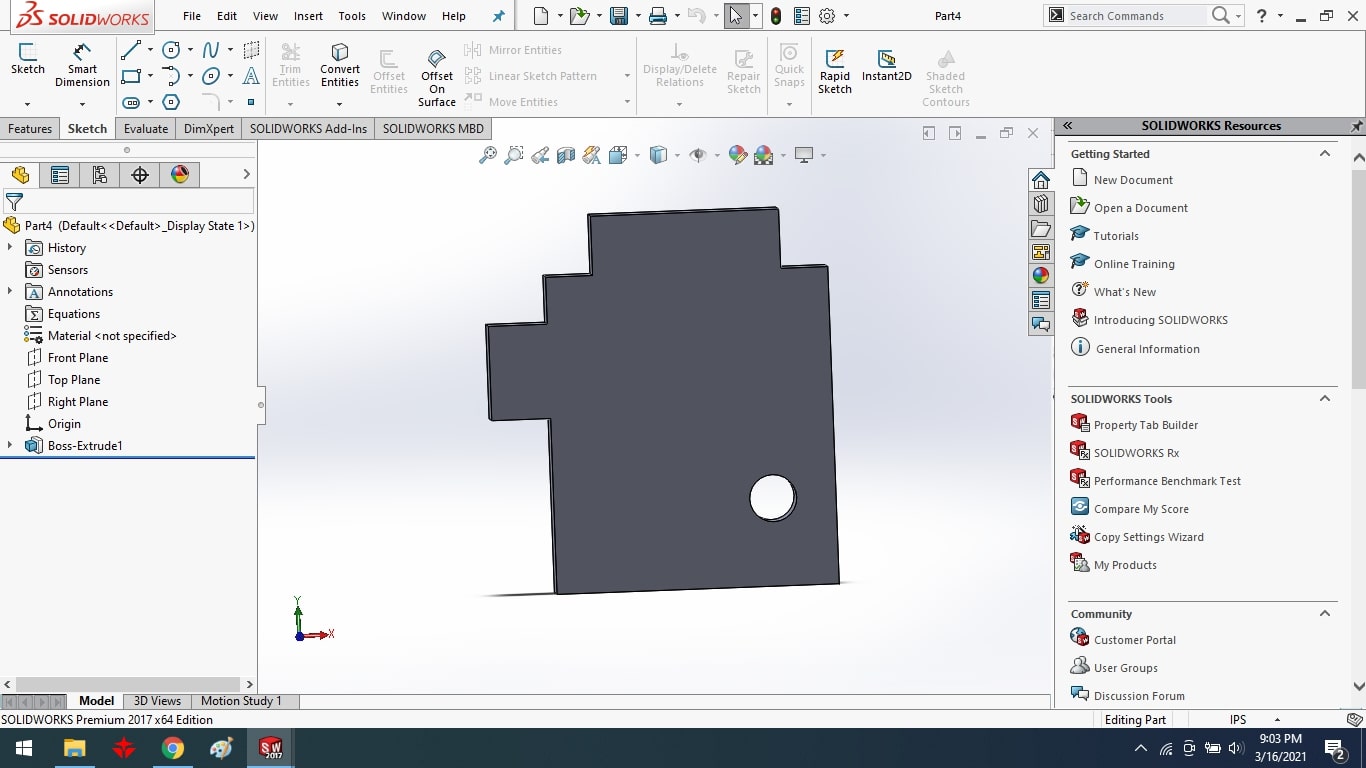
Rod Support
Worm Shaft Support
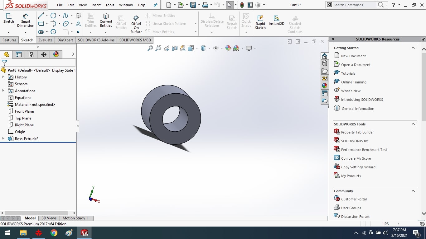
Bolt Bush
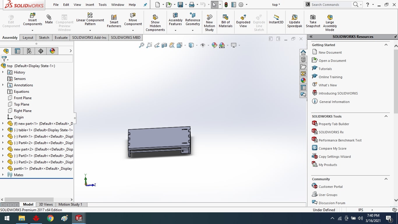
Top Assembly
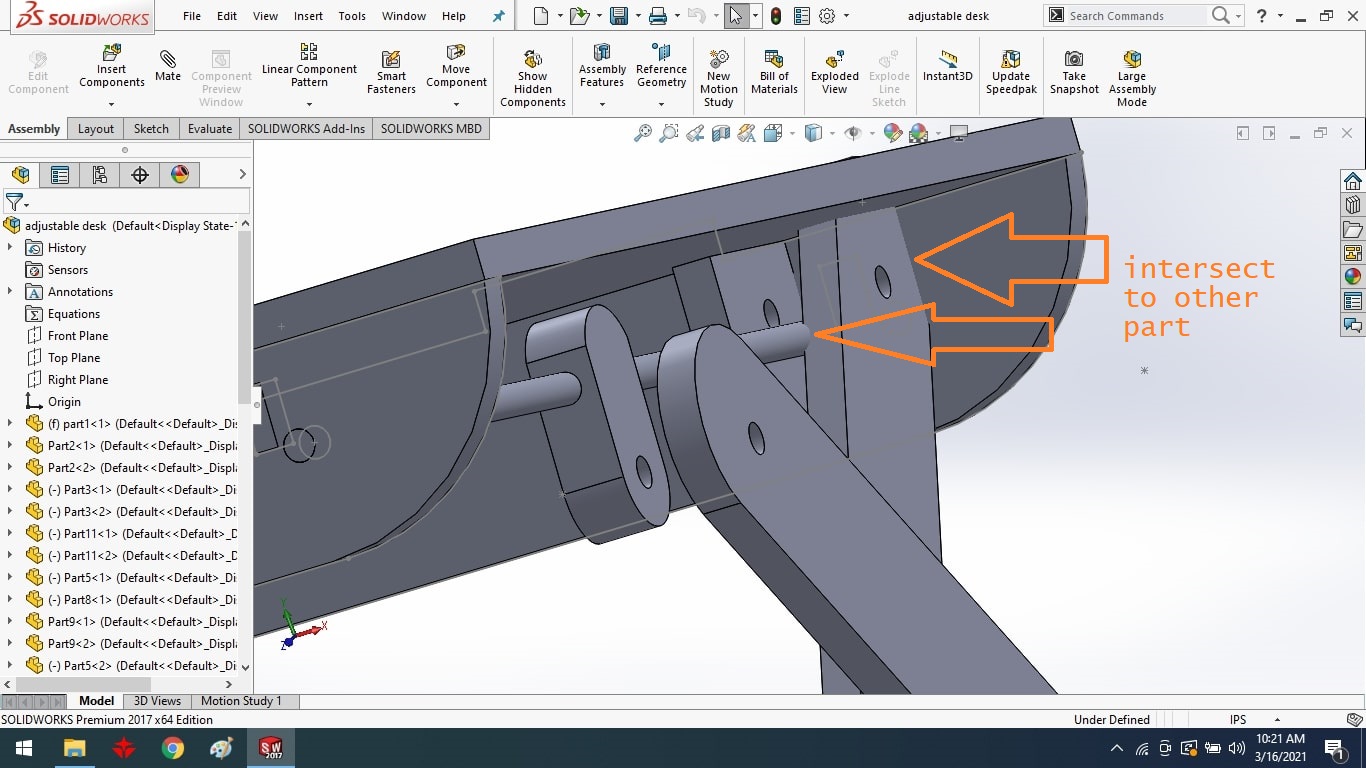
During the assembling of parts, I observed a situation in which the scissor overlaps with another part so I again check all the measurements of components then I identified a problem that is the dimension of both sides of the desk were different.
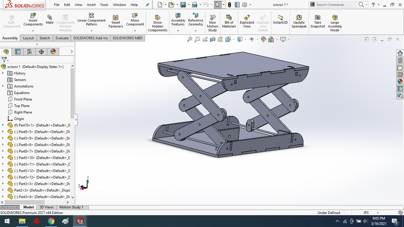
Final Design.
Final Design Video.
Mechanical Part Cutting and Fixing:
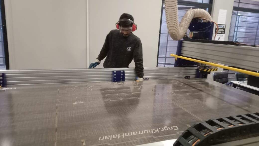
After generating toolpath from VCarve I cut all parts using Shopbot. To learn how to generate toolpath from VCarve please visit Generate toolpath
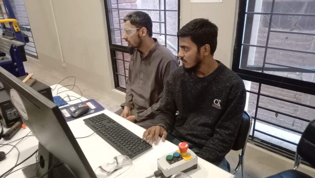
Give file to shopbot in g code format.
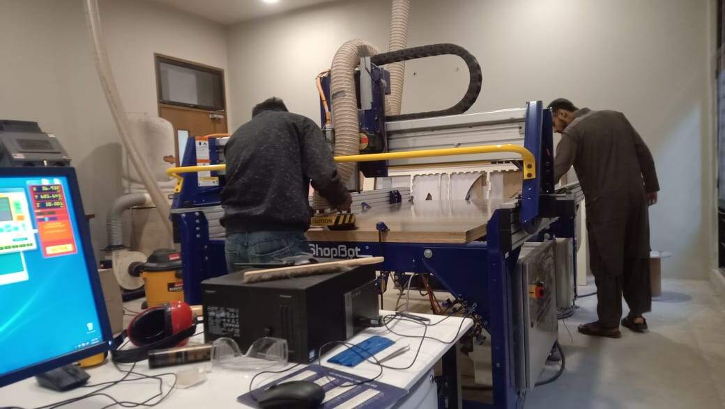
Change the spindle bit.
set the clamp.
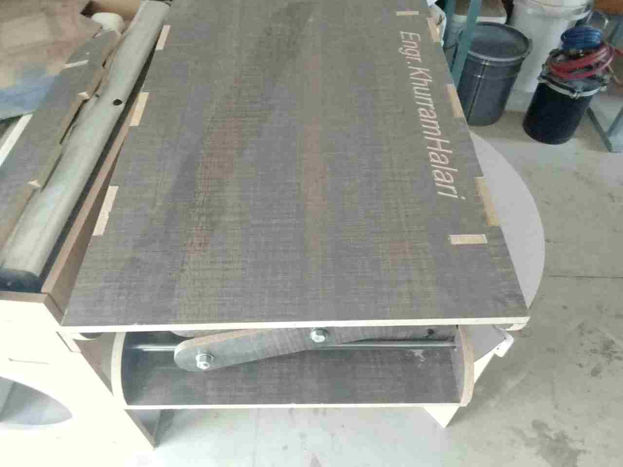
Compelete final structure

Mechanical Design and Problems:
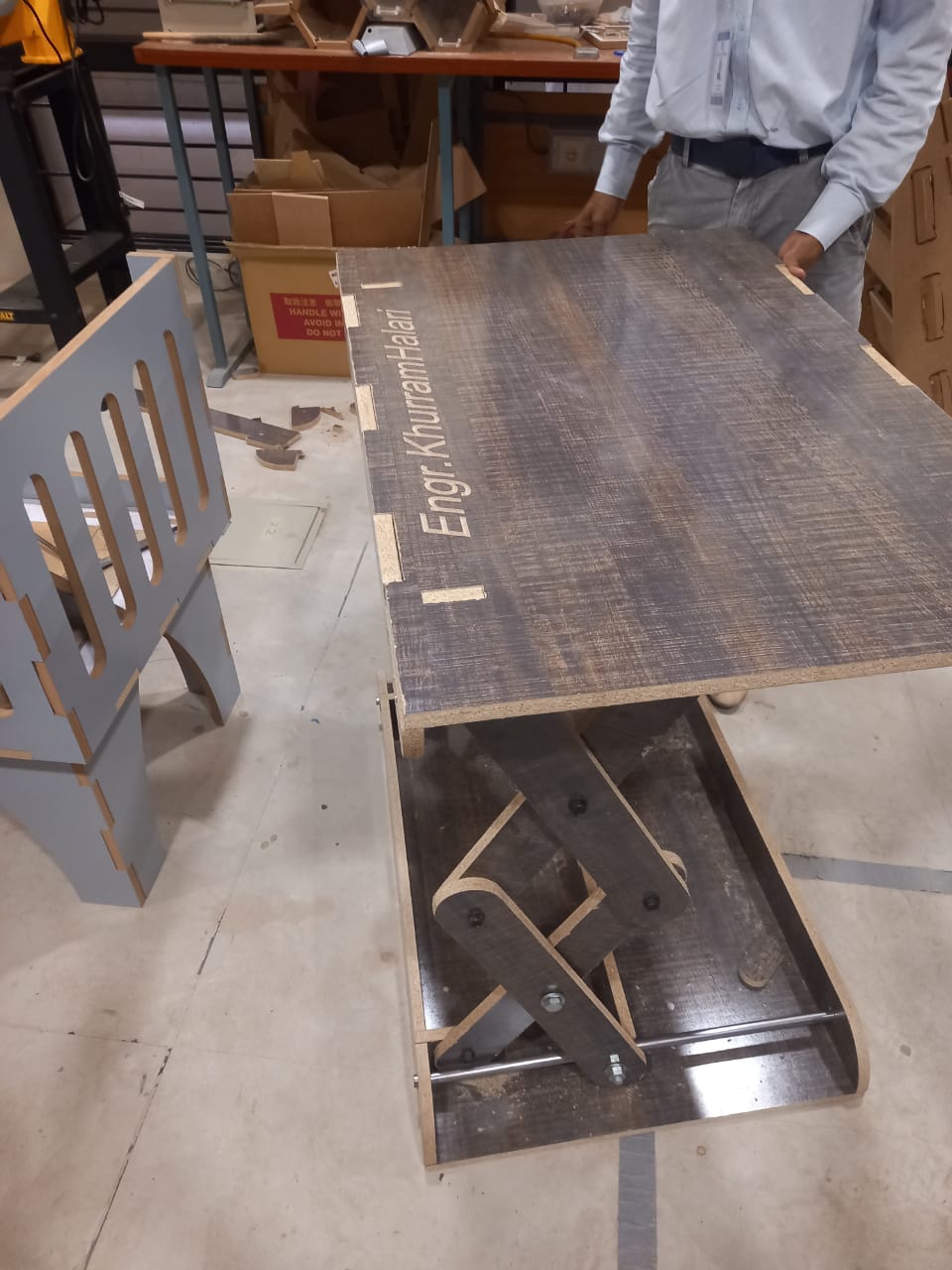
In the beginning, I was trying to use a hollow pipe fitted in wooden pieces for the movement but like wood, it causes so much friction which was affecting the motor and overall performance so I decide to use a solid metal pipe and fitted it with ball bearings to eliminate friction.
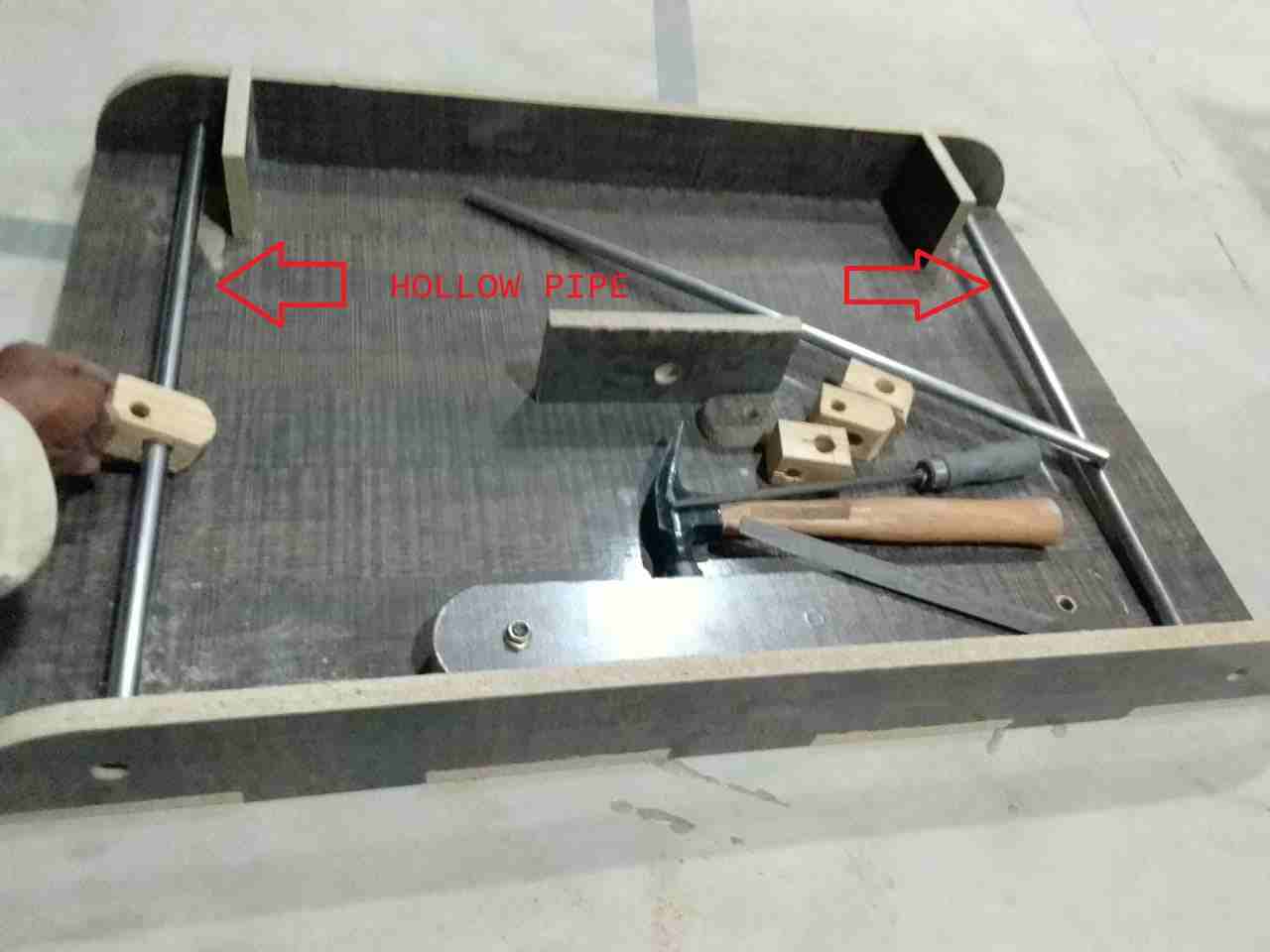
Hollow pipe
The hollow pipe was not in equal dimensions to its ends thus it was another reason to replace it with a solid pipe of 8mm diameter. In addition, to avoid any shedding, good-quality wood was used.

Solid metal rod
Design problem 2:
Initially to drive the load worm shaft was selected but soon it was found that it is not suitable for the operation as it was slipping so it was replaced with a lead screw because it can bear load easily and can drive on a nut.
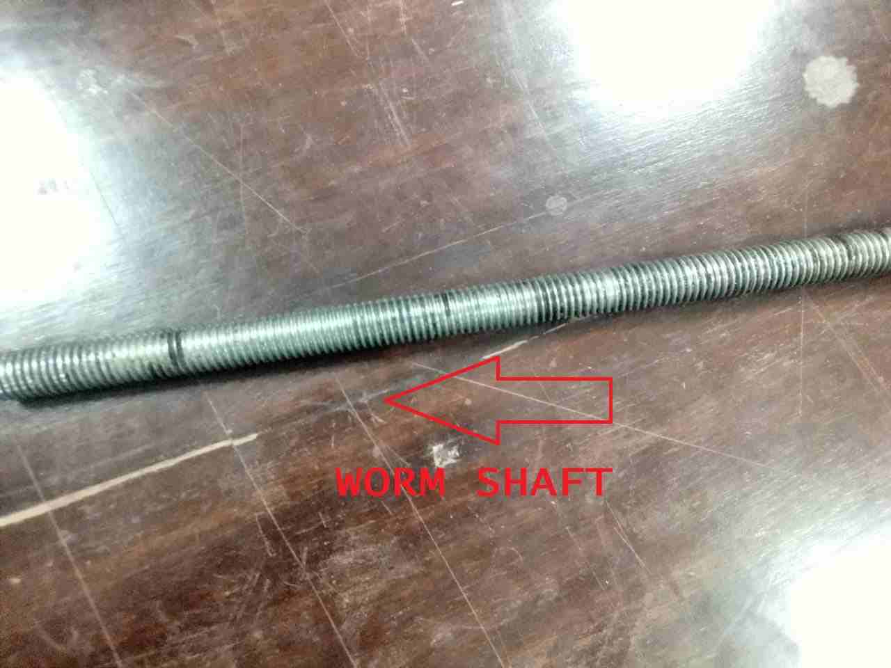
Simple worm shaft
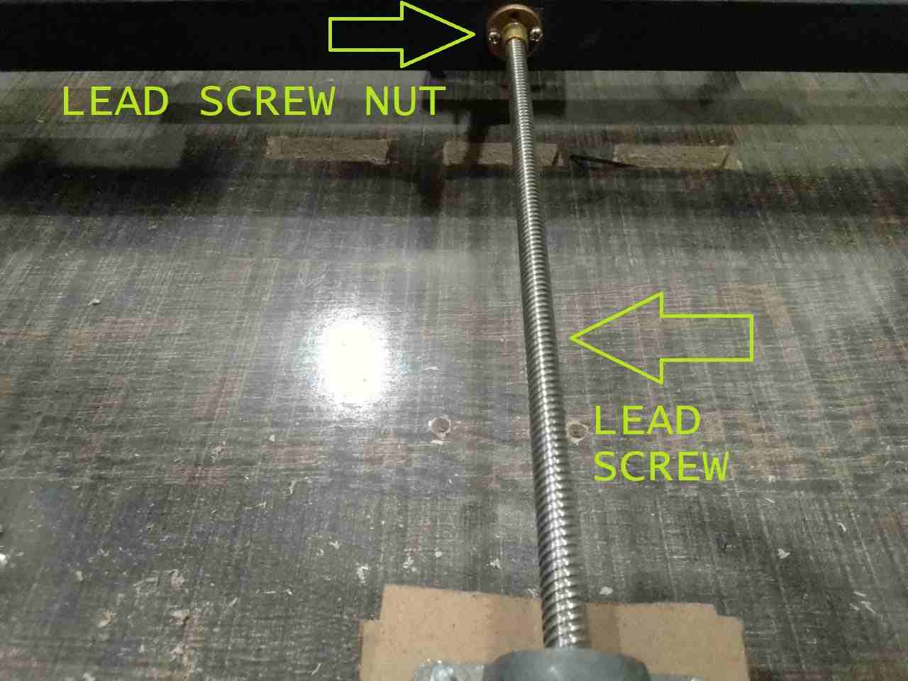
Lead screw with nut
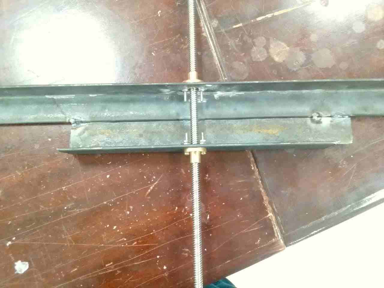
Design problem 3:
As we can see center supporting is made up of a thin metal strip it was not strong enough to move both sides or hold both sides together. So in solution I used strong angle iron and join them together so that both sides move together not back and forth
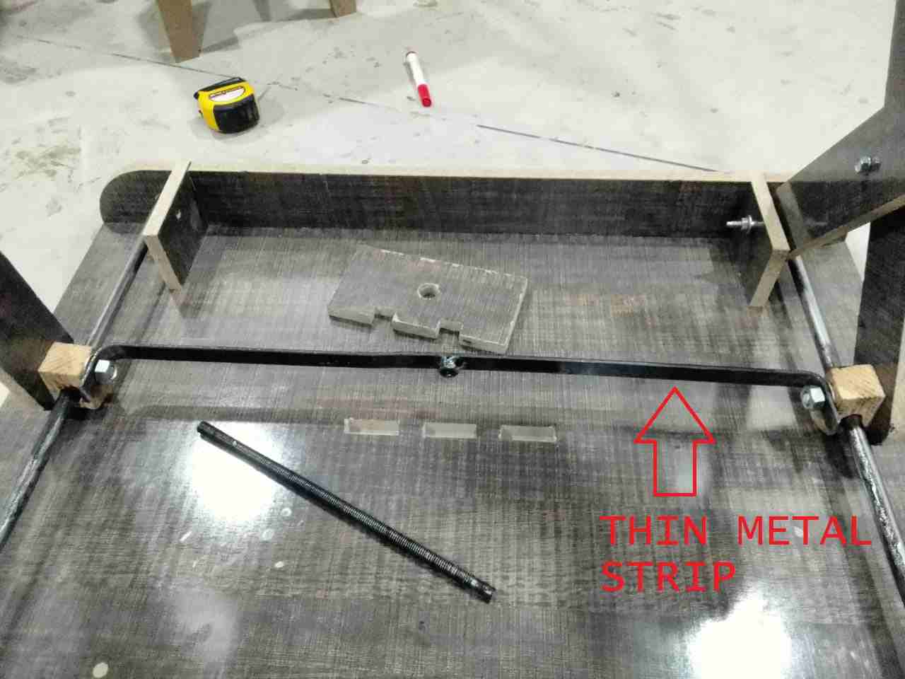
Thin metal strip
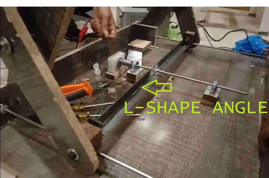
Strong supported Angle
Design problem 4:
Because previous hollow shaft holes were made large because that shaft was 16mm in diameter and we were using an 8mm shaft now. To fit it perfectly and strongly I made plastic bushes
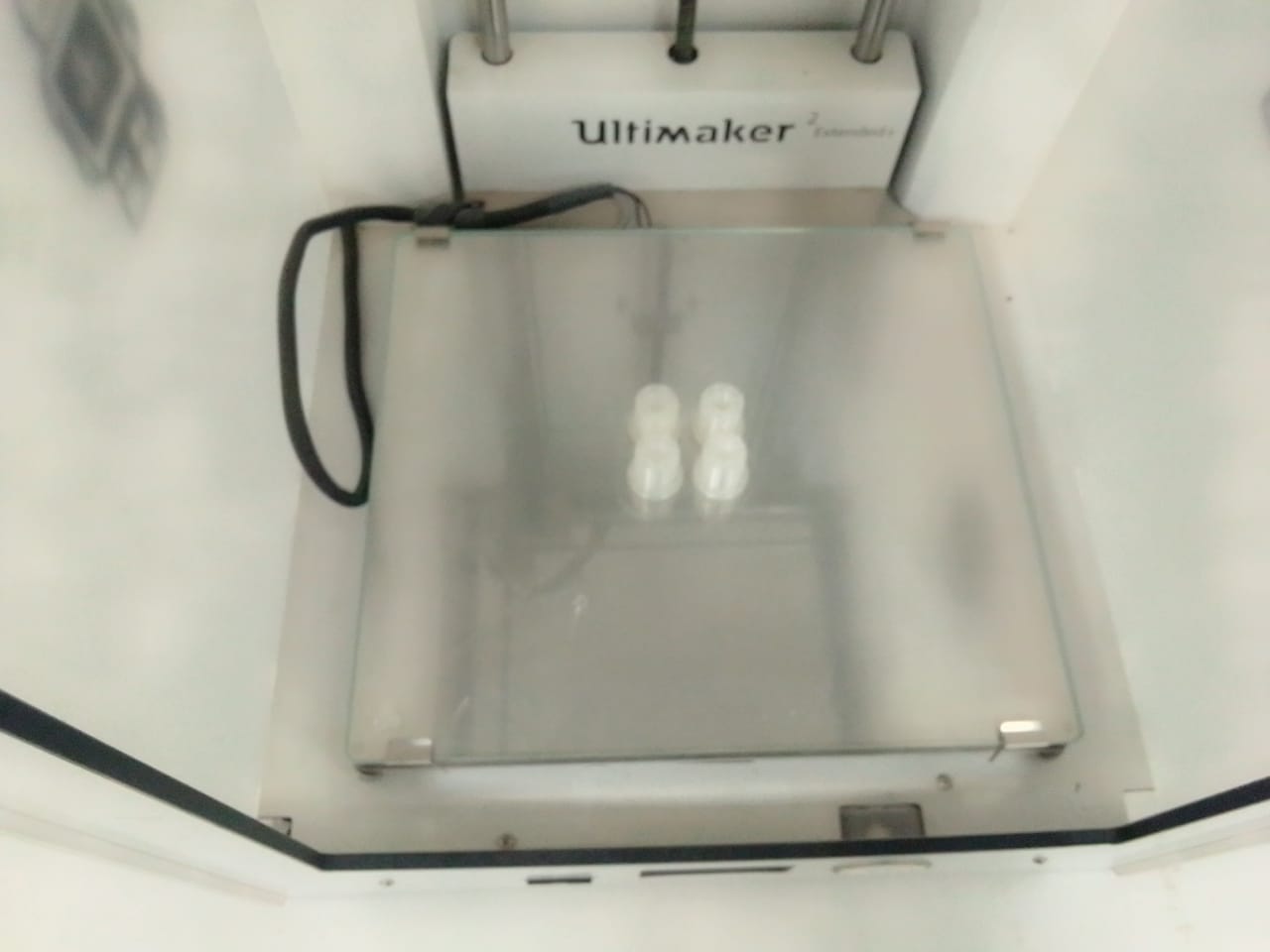
3D printed bush
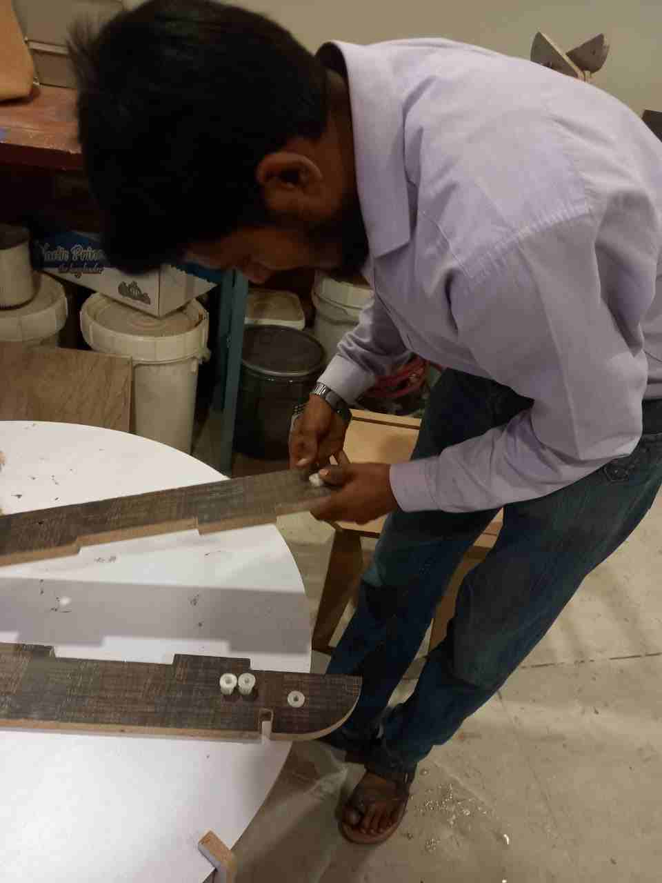
In the wood's holes, I connected bush for supported shaft.
Design problem 5:
But there was another problem created that motor shaft was not aligned with angle iron it had to be raised a little in order to get aligned so I made these clips and supporter that helps motor to be in centre position.
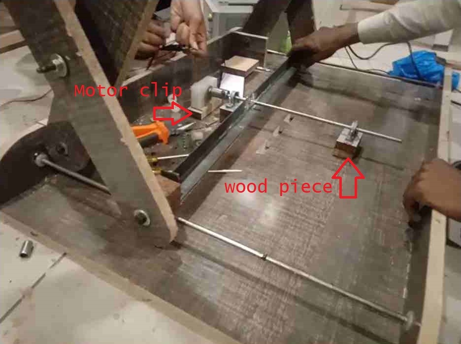
Align motor shaft with center of the angle.
Design problem 6:
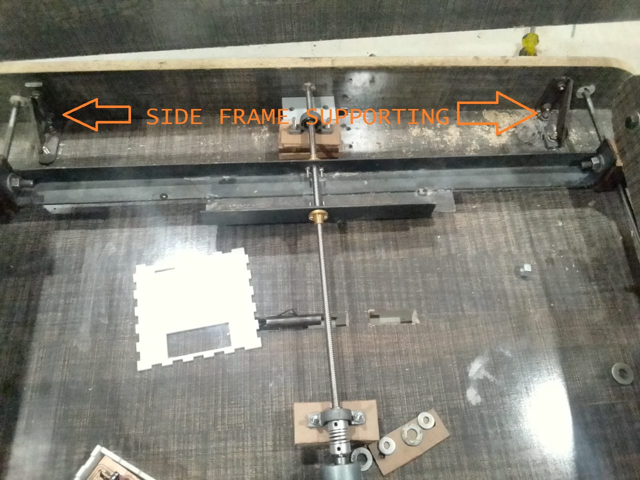
The side frame of the main body was not fixed in the first place while trying I found that it needs to be fixed because it was coming out of its position so this problem was solved by placing a nut to lock this wooden bar into its position
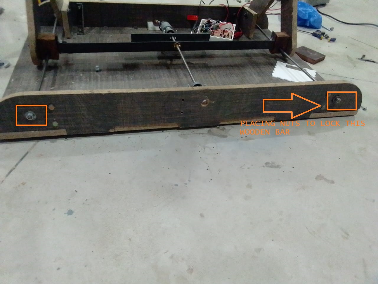
fixed side wooden bar to the steel rod.
Design problem 7:
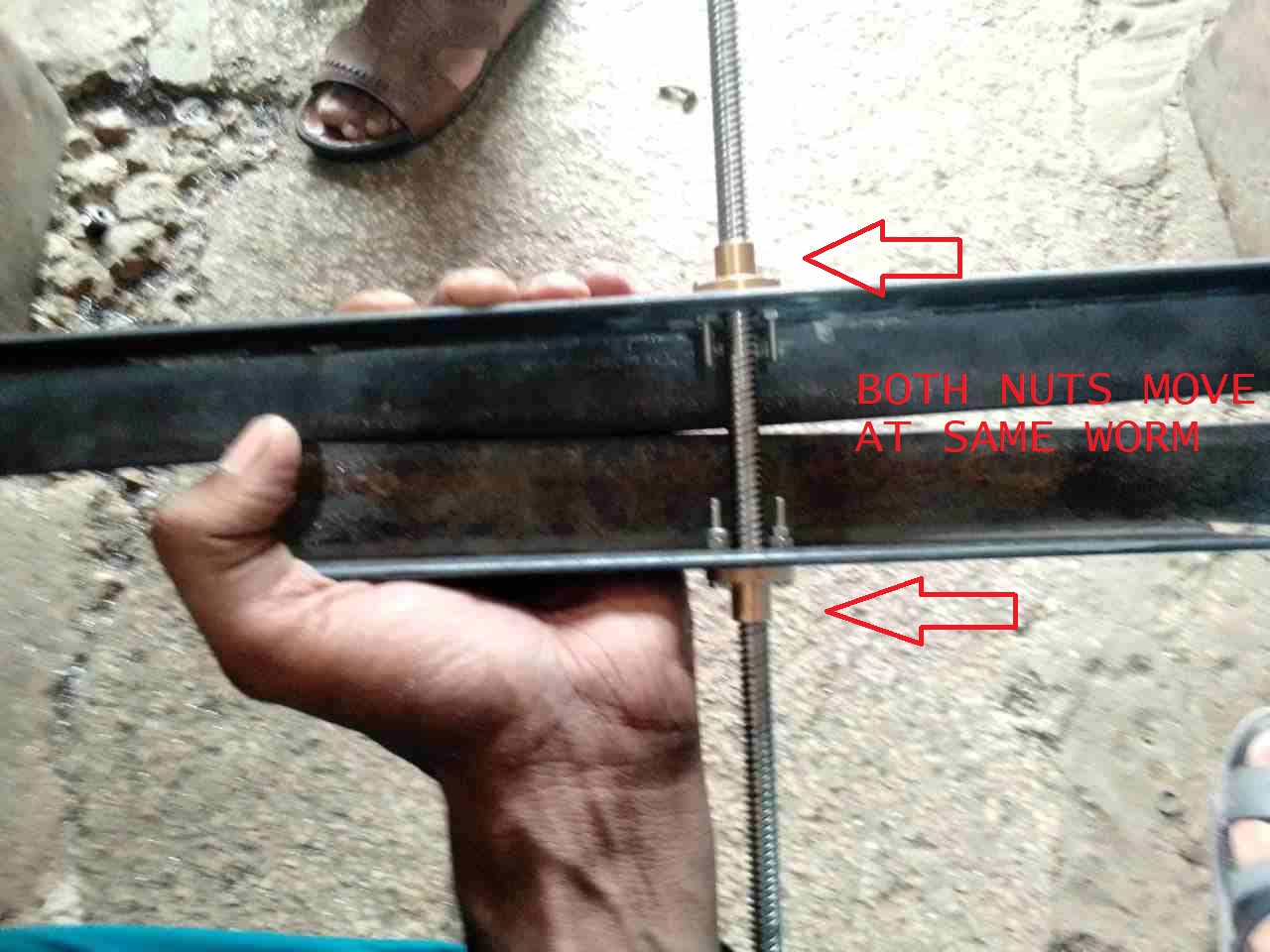
At the same time, align the movement of both nuts in the same direction.
Joined both angles with each other.
Design problem 8:
With the use of a screw for the upward and downward motion, I replace thin strip and replaced it with strong angle iron results was better but not best it has to be improved more so I used another angle as shown in another picture with the use of another angle it was fixed frim and problem was resolved Because of problem that I faced plate was lifting up. So I used these clips and tighten then with a screw from all four sides so that it is held on still position
Iron angle clip for side frame and base support
Experiment:
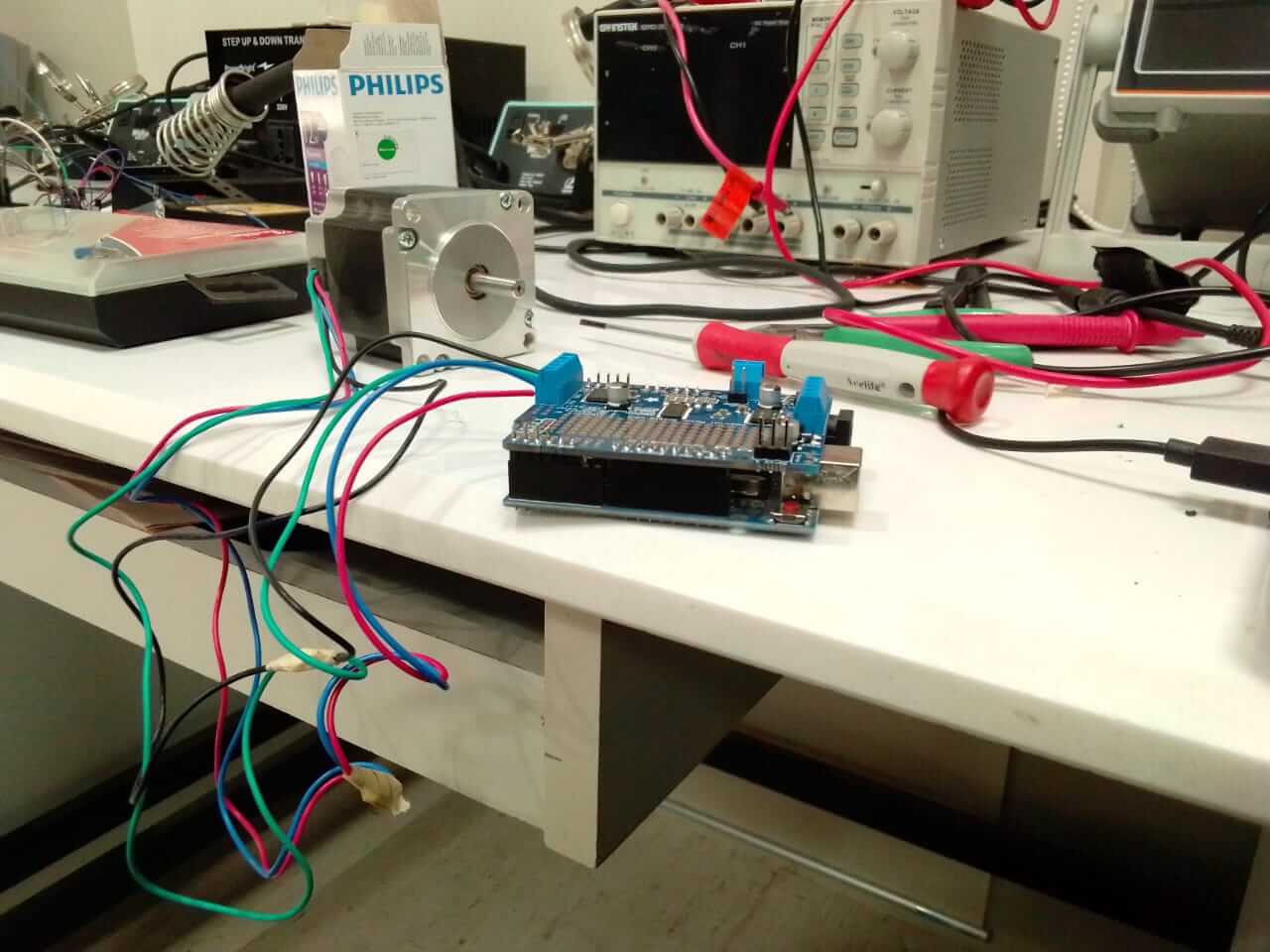
experiment on the different motors for my project.

experiment on stepper motor with L298N driver.
Electronic System
A control device which incorporates a microprocessor.
They are basically current amplifiers which accept the low current signal from the controller and convert it into a high current signal which helps to drive the motor.
A Direct Current (DC) motor is a rotating electrical device that converts direct current, of electrical energy, into mechanical energy.
HC-05 is a Bluetooth device used for wireless communication with Bluetooth enabled devices (like smartphone).
An ultrasonic sensor is an electronic device that measures the distance of a target object by emitting ultrasonic sound waves, and converts the reflected sound into an electrical signal.
I have done my bachelor's in electronics engineering so I have tons of experience in electronic components circuits designing and microcontroller programming etc. Robotics used to be my favorite subject so when coming to mechanical parts I knew what challenges I am going face while designing this project but I got overall development and growth both theoretically and practically.
Microcontroller:
Satsha kit is the main circuit board, which is connected to a DC gear motor driver that drives the motor, an ultrasonic sensor, a 16*2 LCD display, and a Bluetooth module.
Satsha kit:
In my final project, I needed to design and mill a board that can take multiple I/O pins. Therefore, I download Satsha kit board(the board is based on Atmega32U4 microcontroller) files which are already made by Daniel Ingrassia. However, there is one issue with this board: the FTDI cable is not directly connected to upload the program, so some jumper wires are required to upload the program with the help of the Satsha kit, I redesigned the PCB and solved the problem. Now, I am able to complete this process, and I can connect the FTDI cable directly to my microcontroller board to upload the code.
Electronics Design:
Hardware:
As I was so inspired by Arduino and hands-on experience with Atmel family processors and controllers I decided to make my own microcontroller so in order to make that I used Atmega 328 microcontrollers and designed its PCB as shown in pictures.
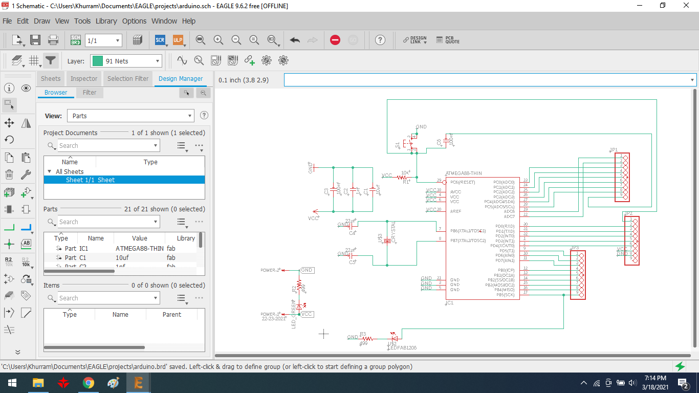
Design a Sketch
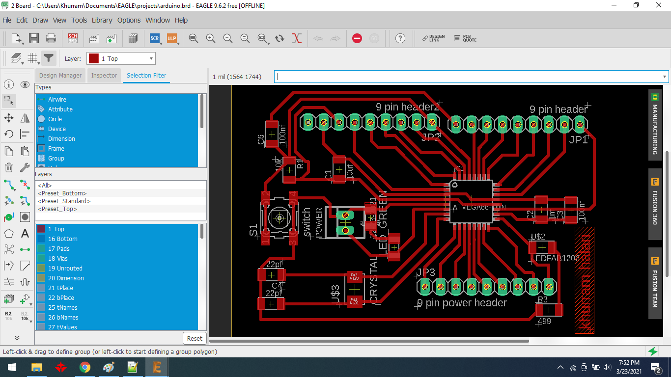
PCB layout

Generating RML file

Components of Arduino(Vastuino) microcontroller

Soldering the components of the arduino circuit.
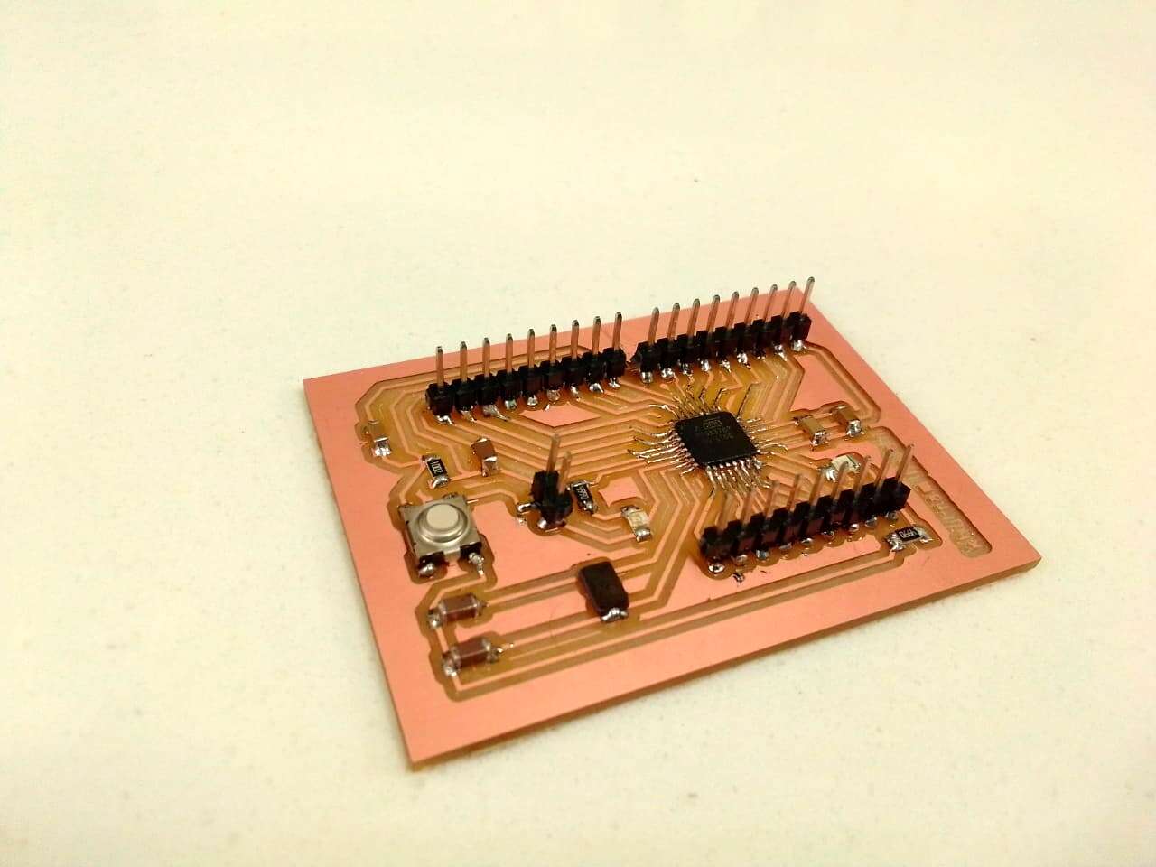
This is my Vastuino Microcontroller.
Motor Driver Board:
In addition to this i also made all modules that were connecting my I/O's like Bluetooth module connecting board my above all my motor driver was designed and made by me in week12
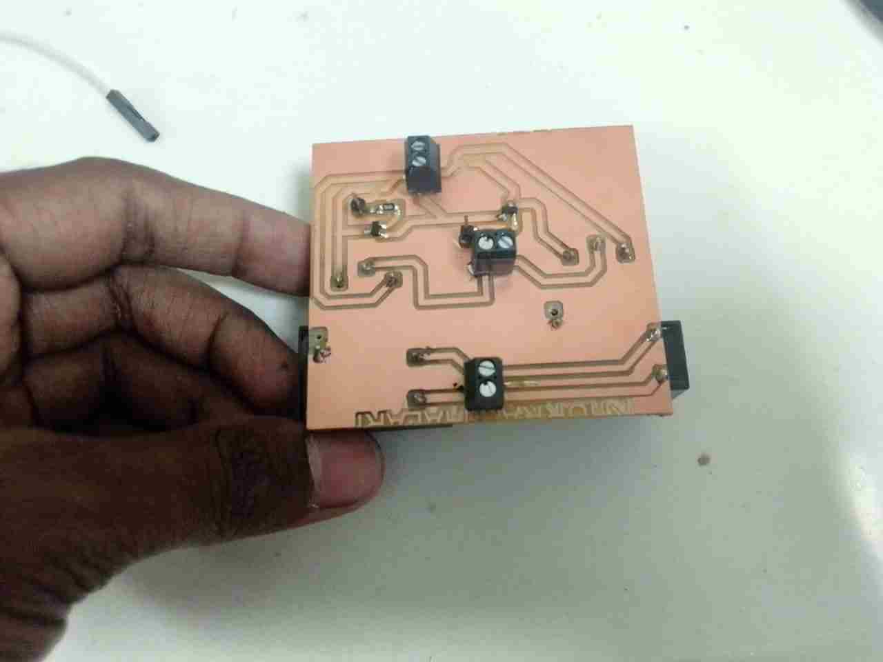
Motor driver PCB
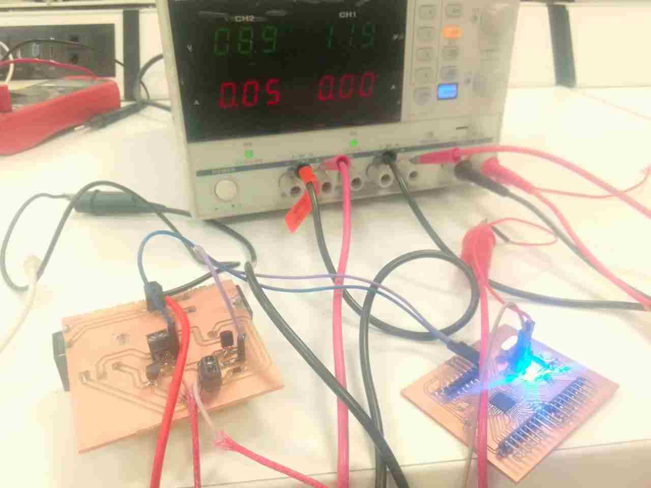
Motor driver connection with Microcontroller
DC gear motor test with driver
Bluetooth module(HC-05)
The HC-05 module is a simple to use Bluetooth SPP (Serial Port Protocol) module that allows for the construction of a transparent wireless serial connection. The Rx and Tx pins of the Bluetooth module were attached to Pin-1 and Pin-0 of the Satsha kit board, respectively.
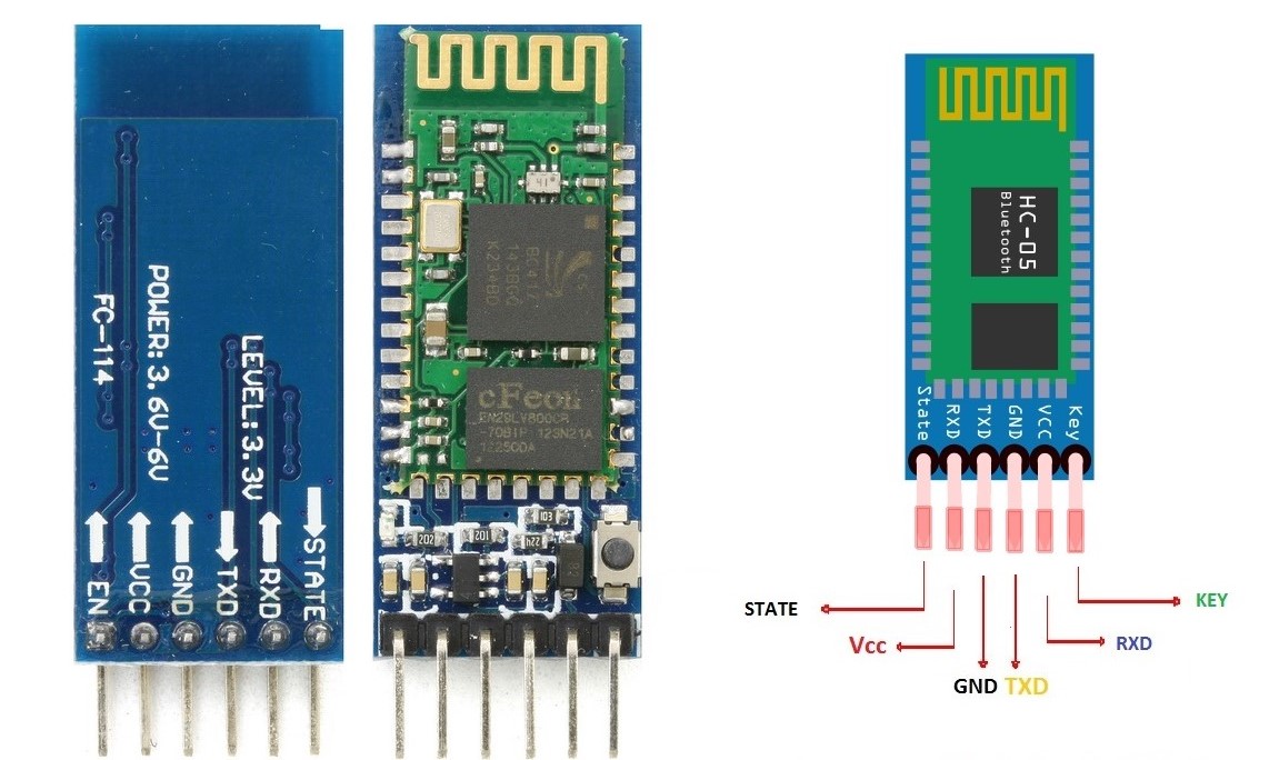
Bluetooth HC-05
Bluetooth module PCB
The voltage divider on the Rx line of the module must be utilised to guarantee that the module does not receive signals over 3.3v before the bluetooth HC-05 may send or receive data from the board. If you need hardware interrupts, you may choose to connect the Bluetooth module directly to the HW serial port in a real-world application. As a result, a voltage divider pcb was created.
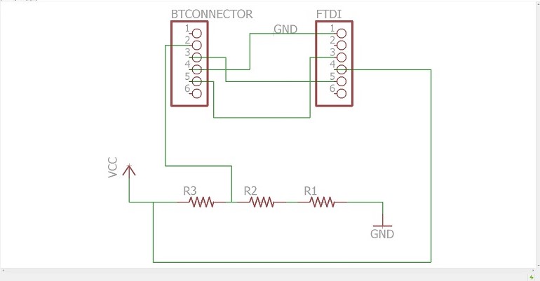
Schematic diagram
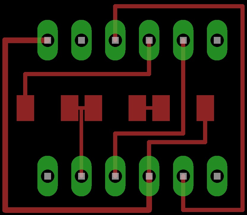
PCB layout
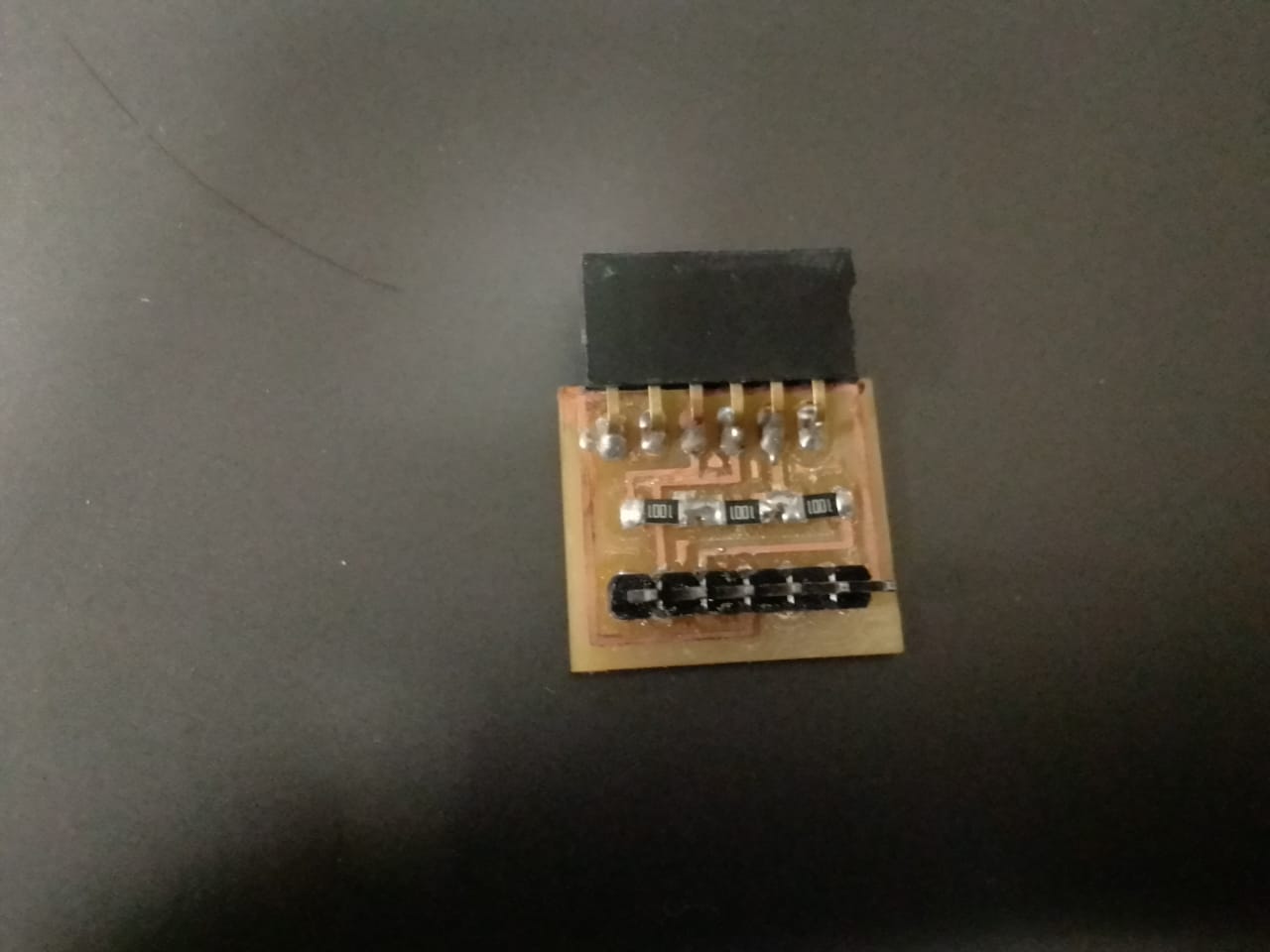
After milling
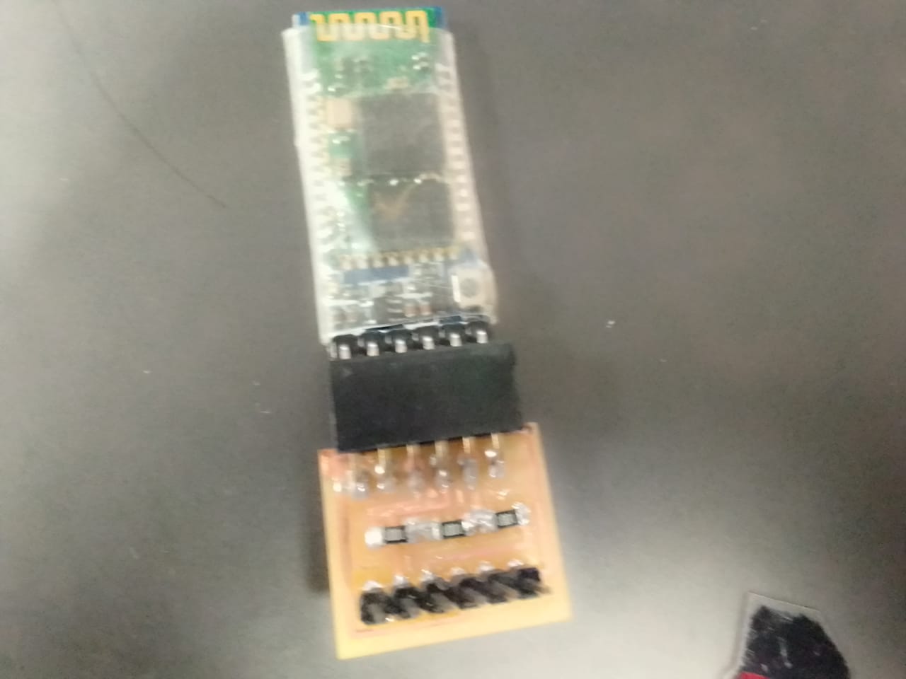
Bluetooth connect with PCB
DC gear motor
These brushed DC Metal Gearmotors are the most powerful and largest you will find on our site. Coming in at a whopping 37mm (1.46) in diameter, they are available in a variety of gear ratios from 6.3:1 to 150:1 at 12V. Composed mostly of spur gears, however the first stage features helical gears for improved efficiency and reduced noise. These motors will run at voltages above and below the rated voltage; lower voltages might not be practical in your project, and higher voltages could start reducing the lifespan of the motor.
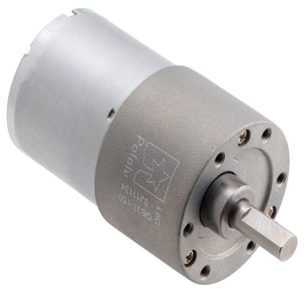
5A Polulu Dc gear motor
Ultrasonic Sensor
An ultrasonic sensor is an electronic device that measures the distance of a target object by emitting ultrasonic sound waves, and converts the reflected sound into an electrical signal. Ultrasonic waves travel faster than the speed of audible sound (i.e. the sound that humans can hear)
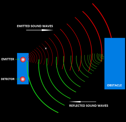
Ultrasonic sensor rays
The HC-SR04 Ultrasonic (US) sensor is an ultrasonic transducer that comes with 4 pin interface named as Vcc, Trigger, Echo, and Ground. The trigger and Echo pins of Ultrasonic sensor are connected with Sasha kit pins 9 and 10 respectively.
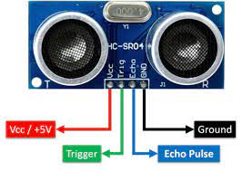
HC-SR04 Ultrasonic Sensor
Source Code:
#include
SoftwareSerial MyBlue(2, 3); // RX | TX
int flag = 0;
int MOTORA =5;
int MOTORB =6;
void setup()
{
Serial.begin(9600);
MyBlue.begin(9600);
pinMode(MOTORA, OUTPUT);
pinMode(MOTORB, OUTPUT);
Serial.println("Ready to connect\nDefualt password is 1234 or 000");
}
void loop()
{
if (MyBlue.available())
flag = MyBlue.read();
else if (flag == 2)
{
digitalWrite(MOTORB, HIGH);
digitalWrite(MOTORA, LOW);
Serial.println("MOTOR BACKWARD");
}
else if (flag == 1)
{
digitalWrite(MOTORA, HIGH);
digitalWrite(MOTORB, LOW);
Serial.println("MOTOR FORWARD");
}
else
{
digitalWrite(MOTORA,LOW);
digitalWrite(MOTORB,LOW);
Serial.println("MOTOR STOP");
}
}
Developing App using MIT app inventor
To connect the Bluetooth module I needed an app of my requirements that will connect my hardware with my phone via Bluetooth. So I choose a tool that I recently learned at Fablab that is MIT app inventor in Week-14 . I used this tool to make my very own mobile application with buttons of my choice so that I can connect my phone to my hardware
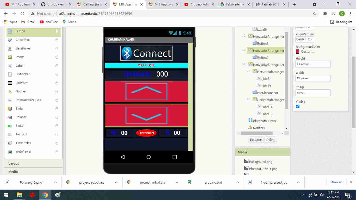
Mobile app
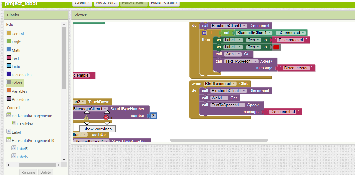
Block diagram
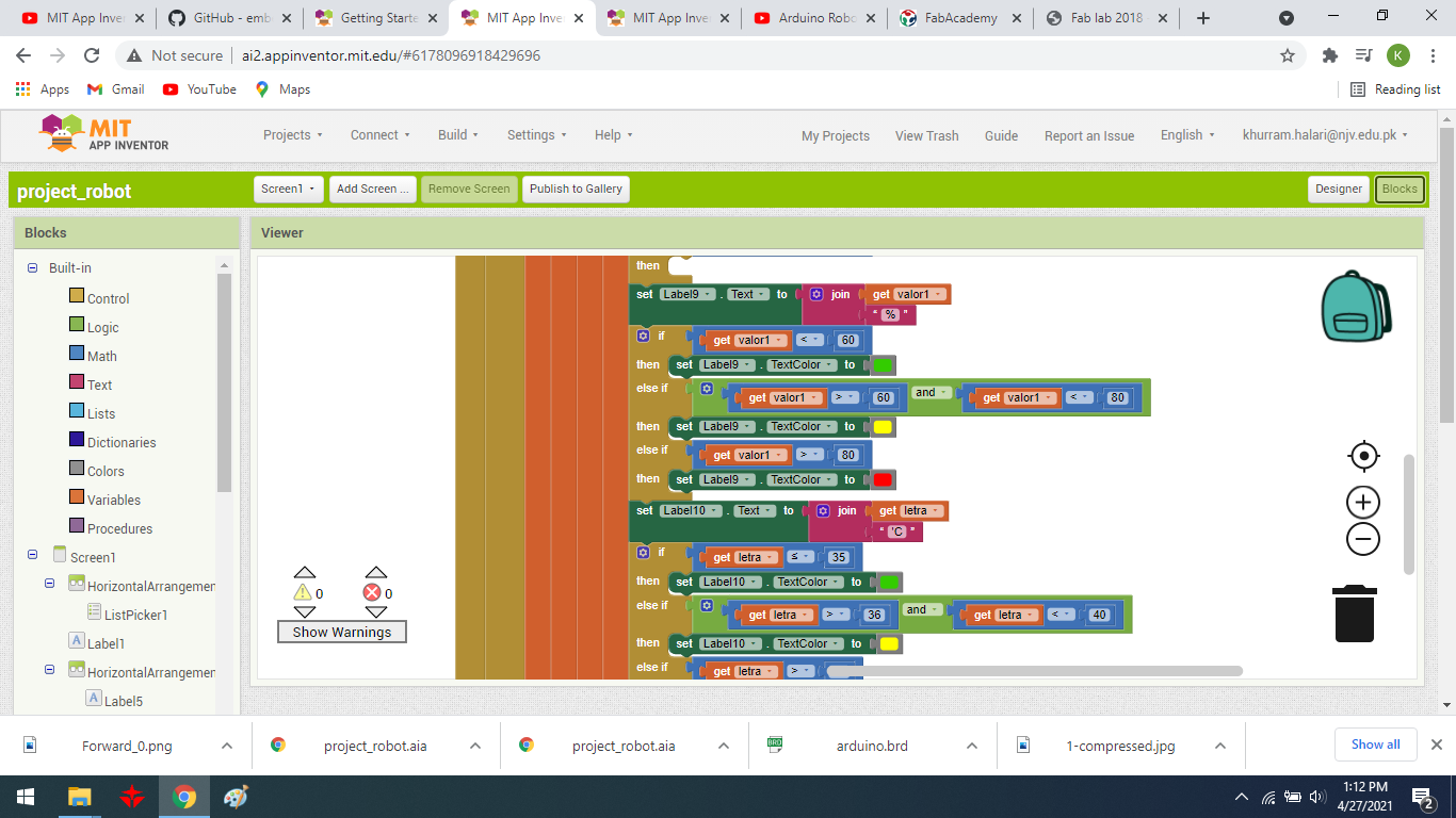
Block diagram
Bill of Material
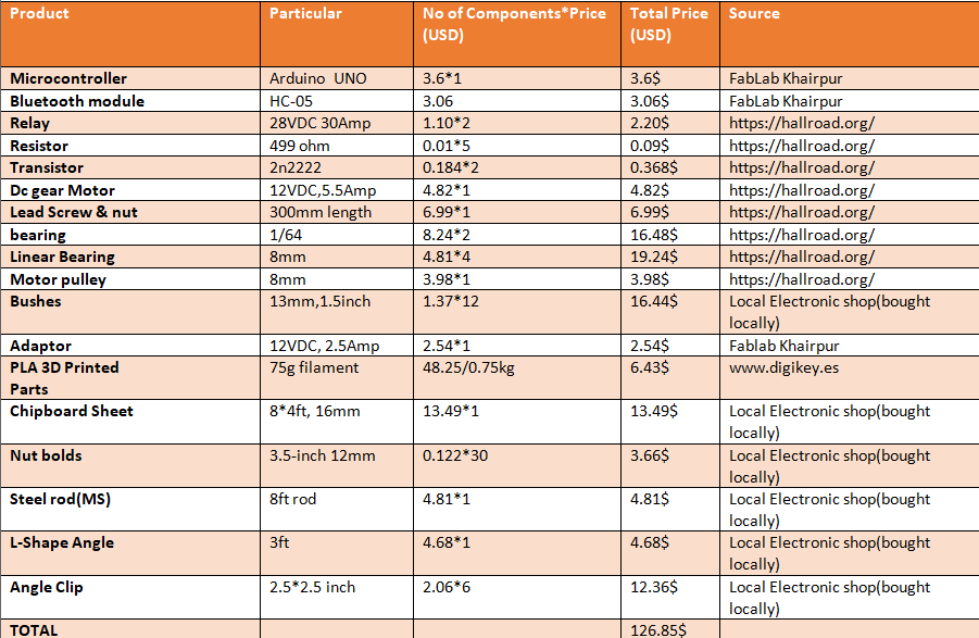
Initially, project estimated cost was around 50 dollars because everything I was using was simple and easy to find I had prior experience of all electronics and motors but as the project was going I came across many problems related to hardware because I had not much experience in mechanical structure and design so most of the challenge I came across was new to me and I had no choice but to perform test and trial and this cost me more energy and money and my BOM was raised to almost 126dollars. My supervisor is sponsored me in some material.
Acknowledgment:
Starting with the greatest name of Almighty Allah, who is the most merciful and gracious, who created the universe, the sun, and the moon, whose worship is our faith and whose love is our everything. I am able to stand where I am right now is all because of him, he provided me the strength and guidance to complete this course. My words are the spectator of the oneness of the glory of Allah and his messenger, Prophet Mohammad (PBUH) whose mercy cannot be described in words.
I cannot express enough gratitude to Professor Neil Gershenfeld, director of Fab Academy who always motivated us and provided us new parameters to learn, and of course, this will not be possible without the platform. So here I am deeply thankful to Vice-chancellor Sir Professor Nisar Ahmed Siddiqui and his team whose effort and vision make FABLAB possible in Pakistan. My completion of this course could not have been possible without the support of my instructors, Noor Ahmed Raza Pirwani and Rasheed Ahmed Qazi, My boss Zaid pirwani HOD of Science and Robotics in NJV Government Higher Secondary School who always have my back. I would like to thanks my family and my friends who supported both financially and emotionally and encouraged me when the time got rough, It was a great relief to know that they are and will be with me in every up and down of my life.
Final Video: (Before Correction)
Final Video: (After Correction)
"Click here"to download all files of this week