BACK TO HOME PAGE
WEEK 12
OUTPUT DEVICE
WEEK ASSIGNMENTS:
Tasks for a week
OUTPUT DEVICE:
What is output device?
(According by google)An output device is any piece of hardware item which utilizes whatever data and commands from your micro controller/processor in order to perform a task. This leads to the results of data processing carried out by an information processing system (such as a microcontroller) which converts the electronically generated information into human-undestandable form.
Now i take small view of all output devices
LED

A light-emitting diode (LED) is a two-lead semiconductor light source. Light Emitting Diode (LED) is the basic example of an output device in electronics Project Blinking LED is called Hello World it is a Diode it works only in forward biased and is available in different colors and sizes.
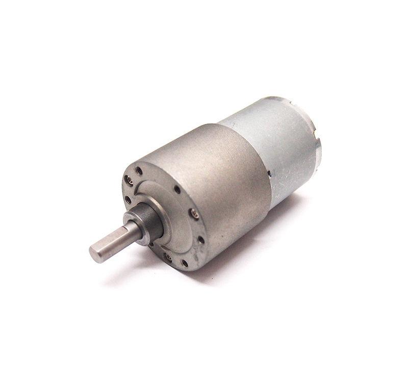
DC Motor
A DC motor is any of a class of rotary electrical machines that converts direct current electrical energy into mechanical energy. The most common types rely on the forces produced by magnetic fields. Nearly all types of DC motors have some internal mechanism, either electromechanical or electronic, to periodically change the direction of current flow in part of the motor.
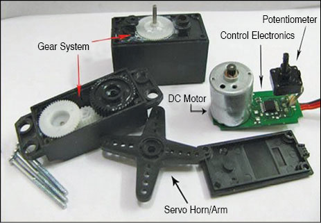
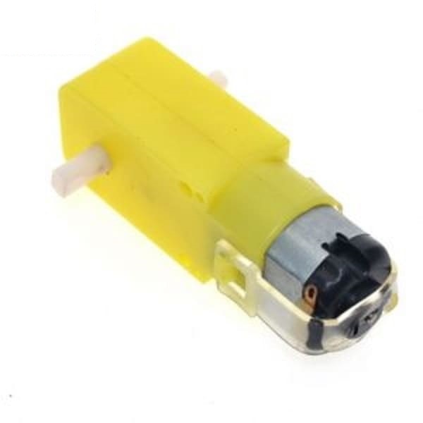
DC Gear Motor
A gear motor is an all-in-one combination of a motor and gearbox. The addition of a gear head to a motor reduces the speed while increasing the torque output. ... Most of our DC motors can be complimented with one of our unique gearheads, providing you with a highly efficient gear motor solution.
Stepper Motor
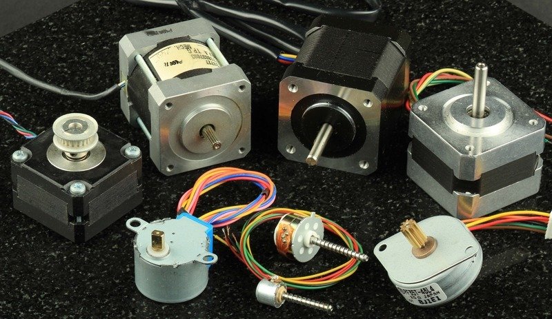
A stepper motor is a brushless, synchronous electric motor that converts digital pulses into mechanical shaft rotations. Each rotation of a stepper motor is divided into a set number of steps, sometimes as many as 200 steps. The stepper motor must be sent a separate pulse for each step.
Relay
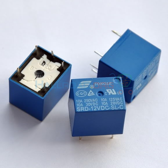
A relay is an electrically operated switch. Many relays use an electromagnet to mechanically operate a switch, but other operating principles are also used, such as solid-state relays. Relays are used where it is necessary to control a circuit by a separate low-power signal, or where several circuits must be controlled by one signal. The first relays were used in long distance telegraph circuits as amplifiers: they repeated the signal coming in from one circuit and re-transmited it on another circuit.
LCD
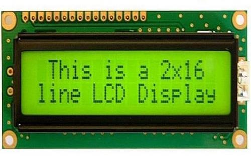
LCD (Liquid Crystal Display) screen is an electronic display module and find a wide range of applications. A 16x2 LCD display is very basic module and is very commonly used in various devices and circuits.
Task:01 Add an output device to a microcontroller board:
Machine used:
Software used:
Individual Assignments:
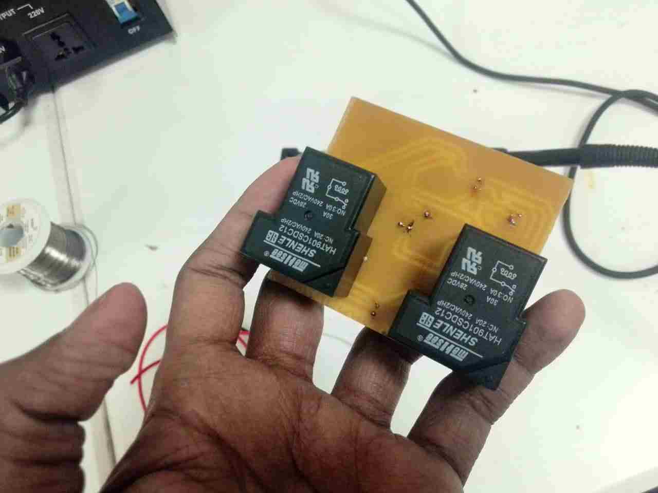
As part of my final project, I want to design a high-ampere (voltage is 28VDC & Current is 30A) DC motor driver to control a DC gear motor. Since I need to control the motor in both directions, I use two relays in my module.
Problems:
To begin, I had some difficulties designing a motor driver. The following issues are listed below.
Design a skectch:
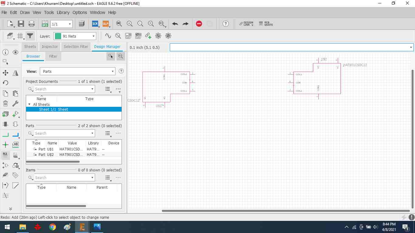
Adding a relay using the add part option on the left side toolbar
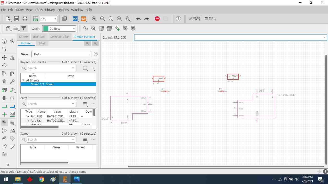
Adding two transistors for motor movement in both directions.
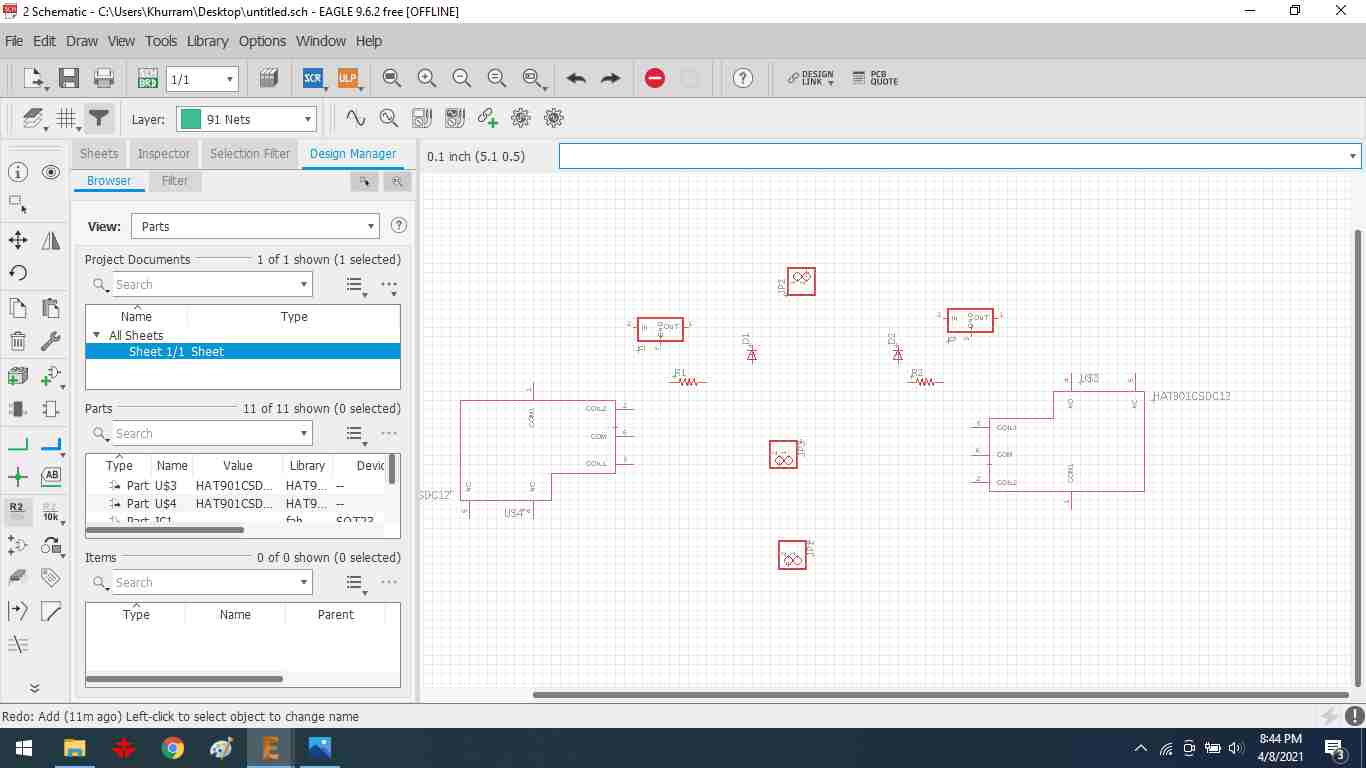
Basic components that are used in the schematic.
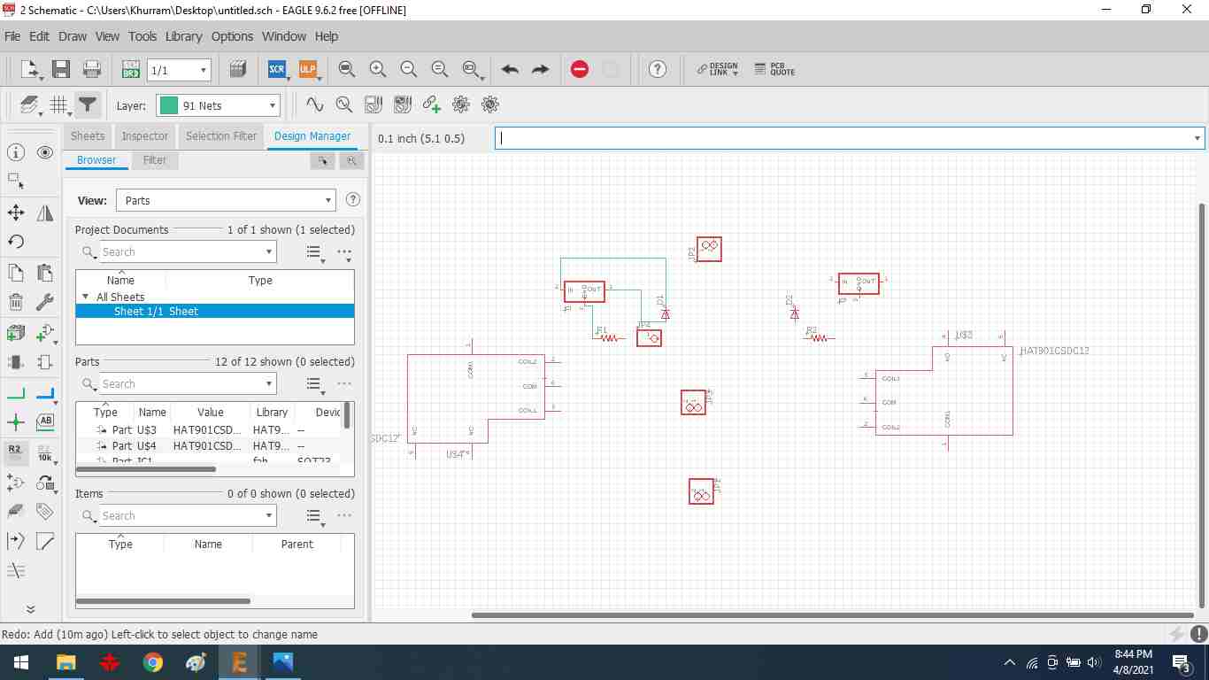
Then, using the net tool on the left side toolbar, I make a route.
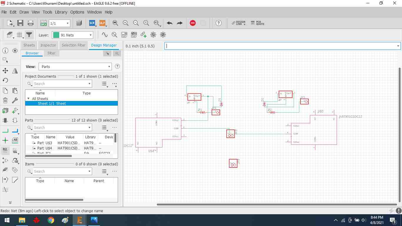
relay connection


Add terminal block for external supply.
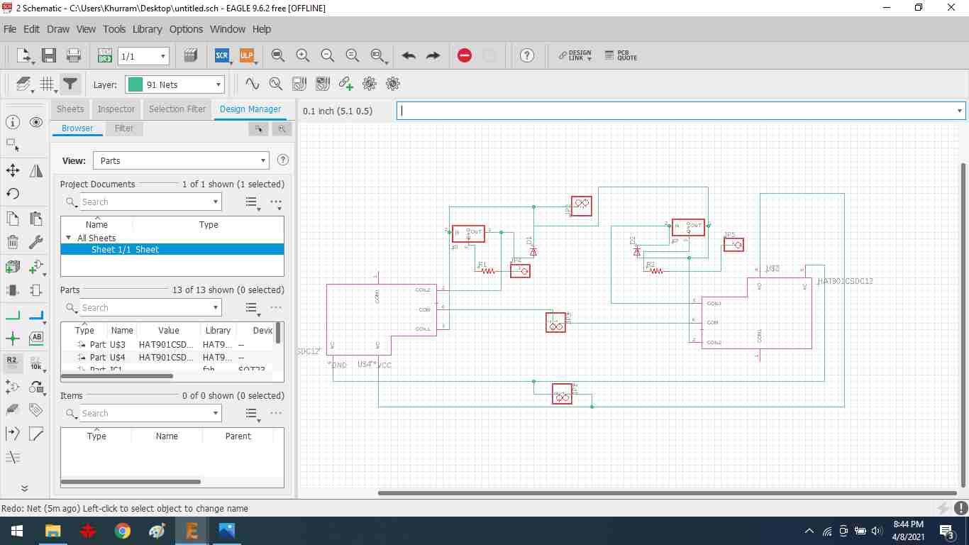
rearranging the components' locations
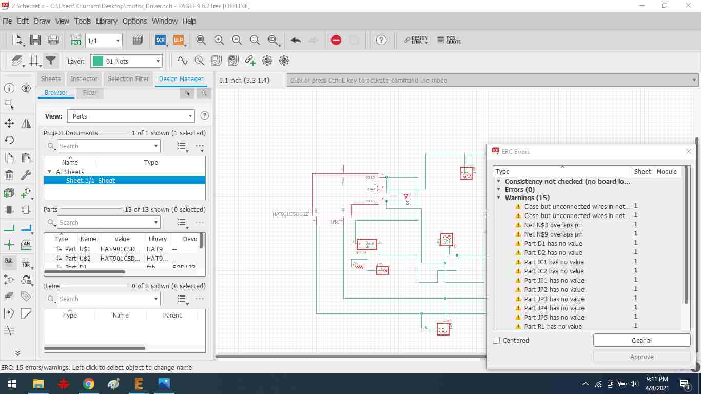
remove different types of errors.
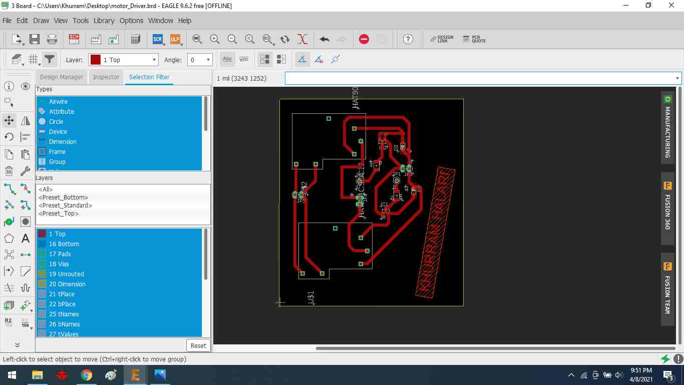
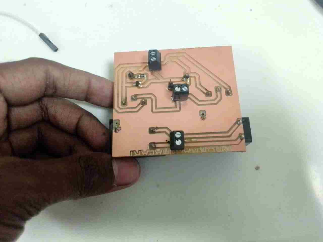
completed PCB file for the Motor Driver Board.
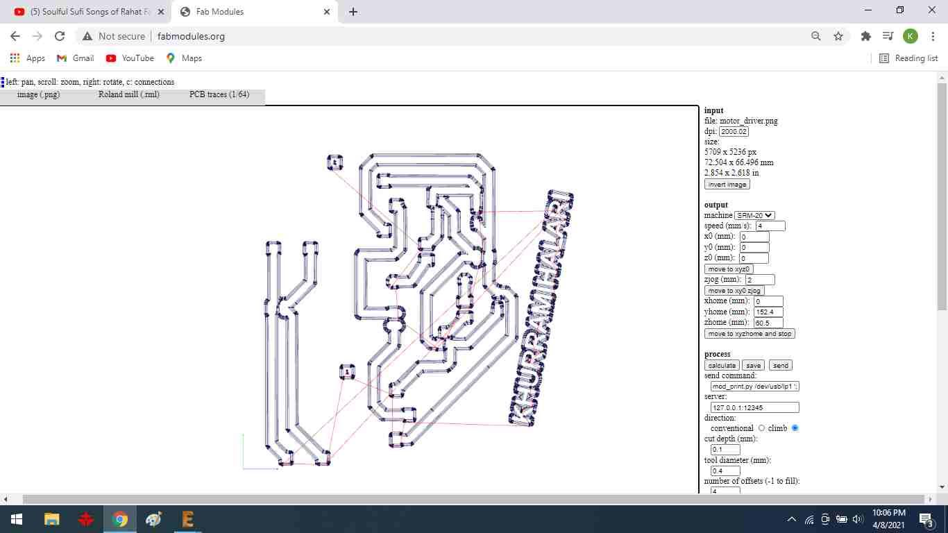
When generating the rml file, double-check the layer intersection.
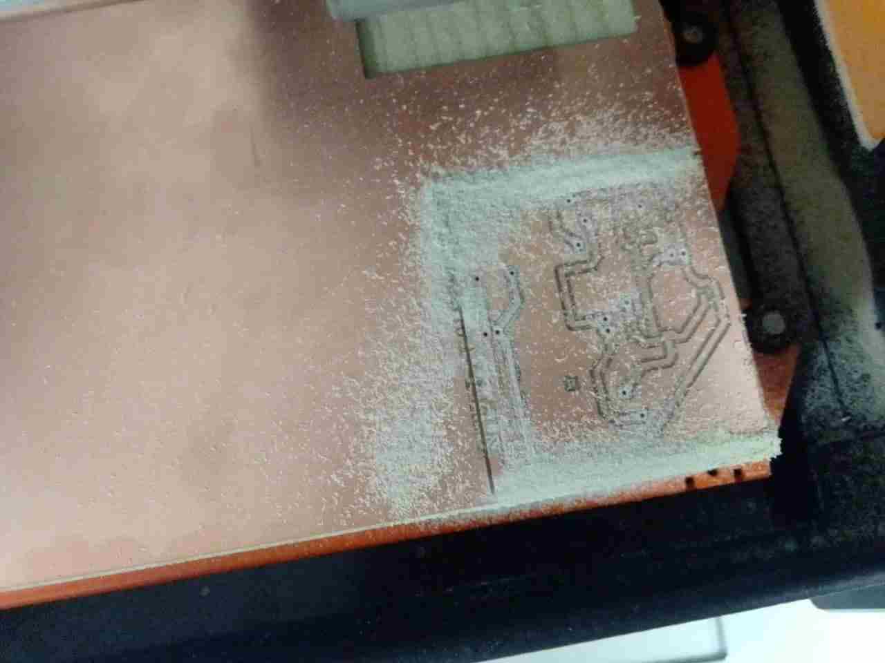
FINAL RESULT:
Connection:
To begin, I used the internet to get the idea for a relay driver. I'm thinking of making a single-direction DC motor relay driver. However, I've never worked with a dual-direction relay driver circuit before.
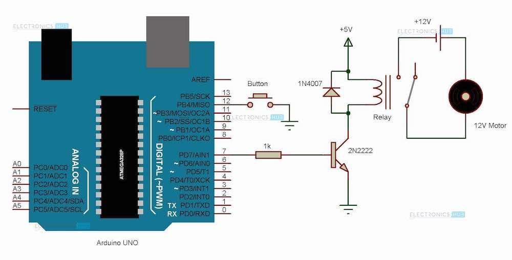
Connection diagram.
I have sketched the connection diagram of motor driver with arduino pin on a papper.
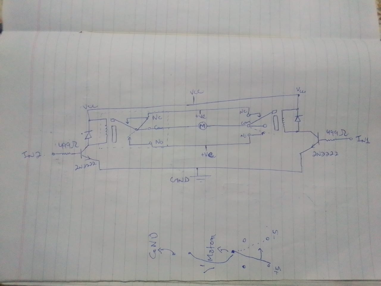
Sketch diagram.
Hero shot of my final outcome.
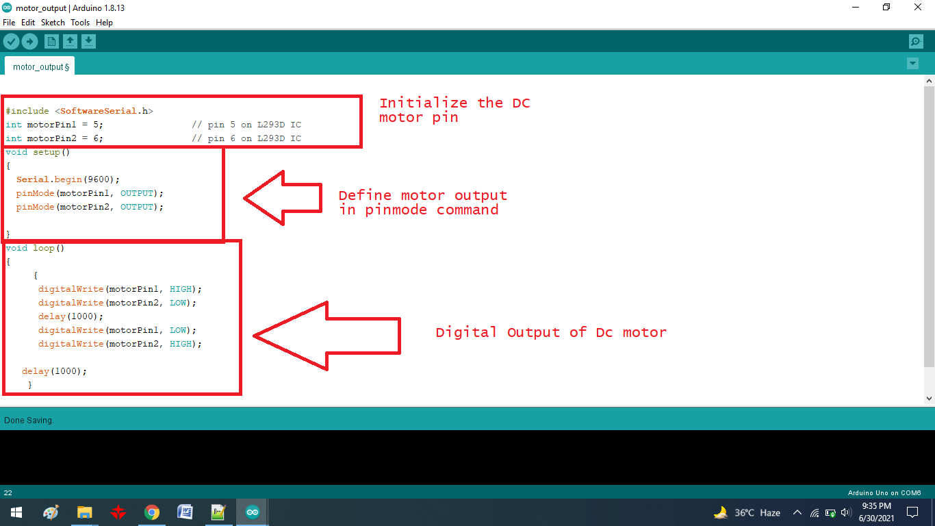
Programming:
I wrote the DC motor code in Arduino software, uploaded it to the Microcontroller, and connected the motor driver to test the DC motor after creating the PCB board for the Motor Driver.
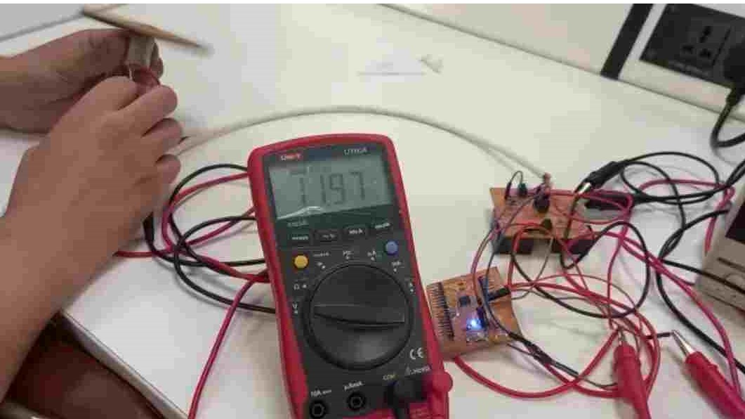
FINAL VIDEO:
Task:Group assignment:
measure the power consumption of an Motor driver circuit.
We decided to find the power usage of motor drivers on various DC motors because one of our projects is about motor driver circuits. On that initiative, we take current measurements.
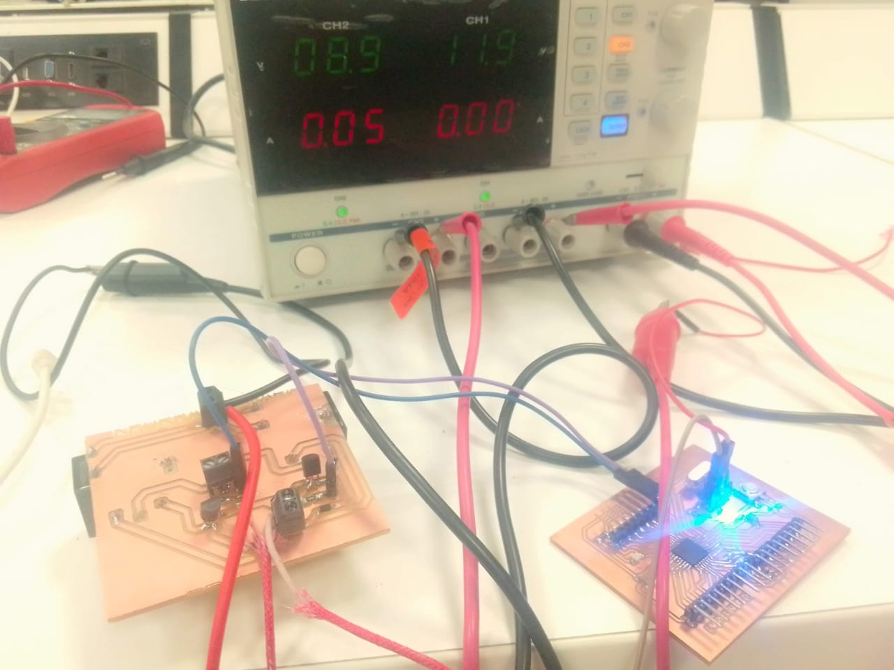
The input voltage is 12 volts.
The current drawn by a simple DC motor is 89.2mA.
A simple DC motor consumes 1.06W watts of total power.
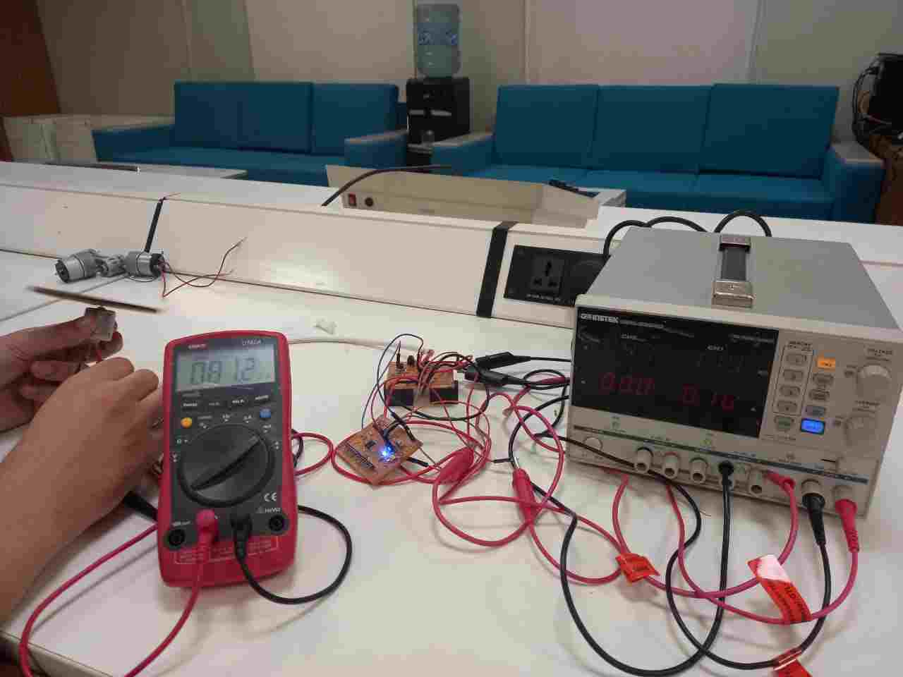
The current drawn by a DC gear motor is 165.4mA.
The total power consumption of DC gear motor is 1.884W.
"Click here"to download all files of this week