BACK TO HOME PAGE
WEEK 7
COMPUTER CONTROLLED MACHINE
WEEK ASSIGNMENTS:
Tasks for a week
Task:01 To make some thing big:
Machine used:
Software used:

This week assignment content:
INDIVIDUAL ASSIGNMENTS:
PROBLEMS:
MAKE SOMETHING BIG
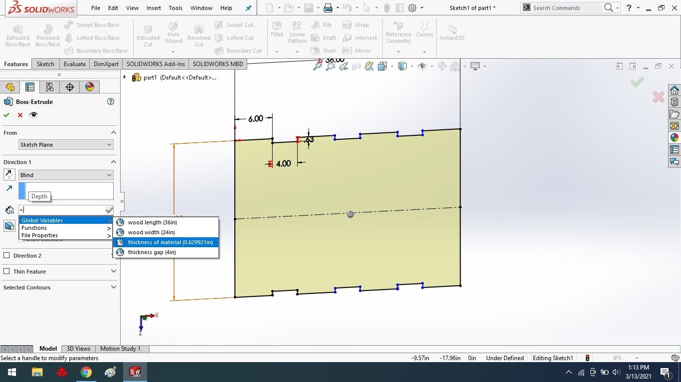
To design 3D model of final project:
To begin, I created the top part of my final project using a parametric equation and the line tool.
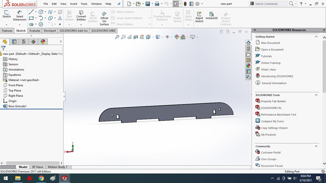
I used the line tool to design the bottom part of my final project.
After that, I extruded the bottom part with the extrude boss tool.
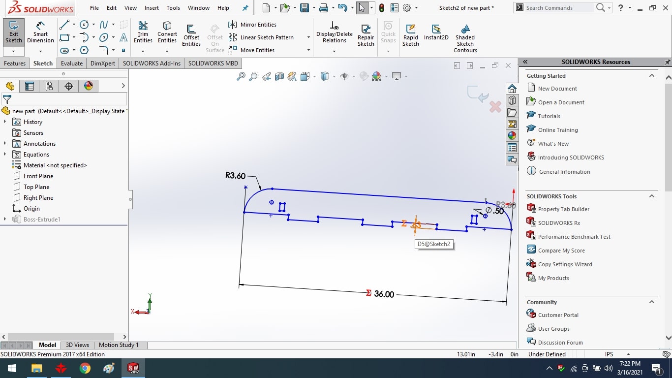
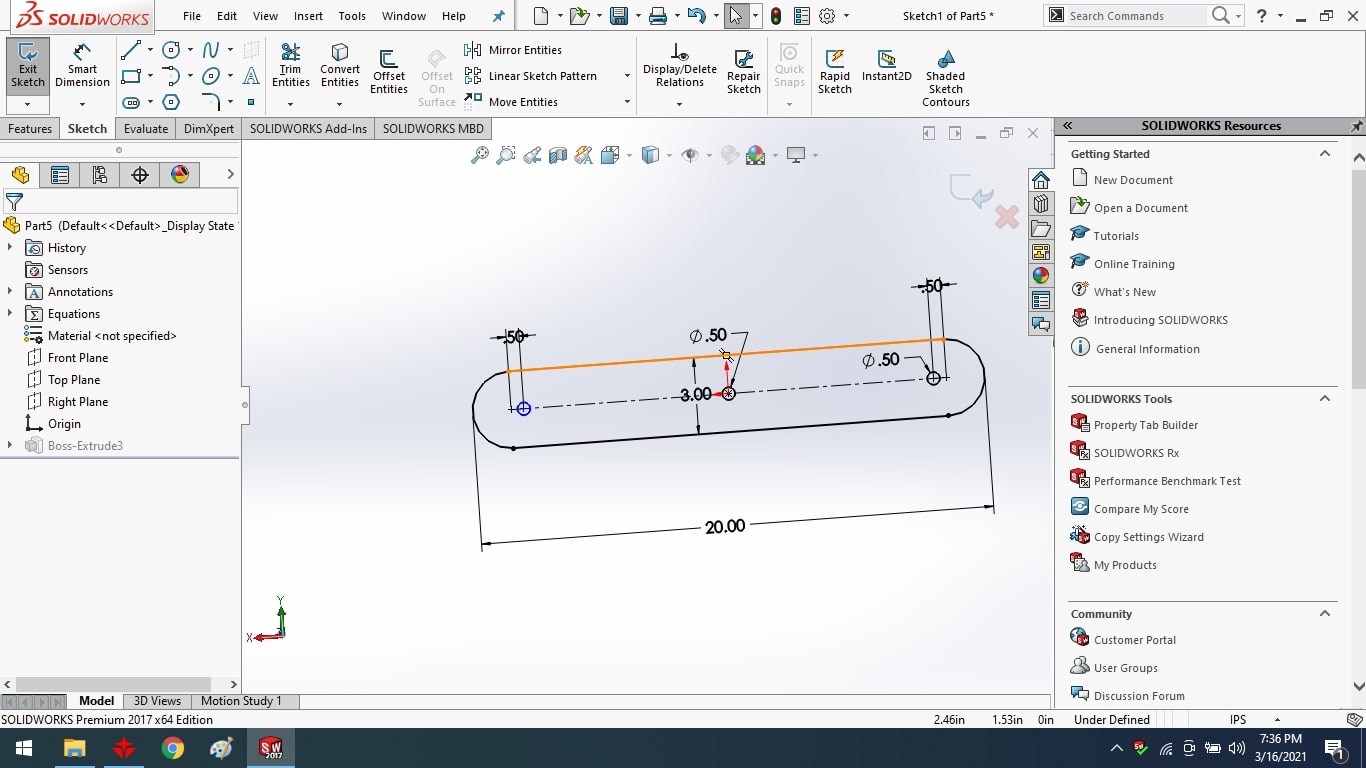
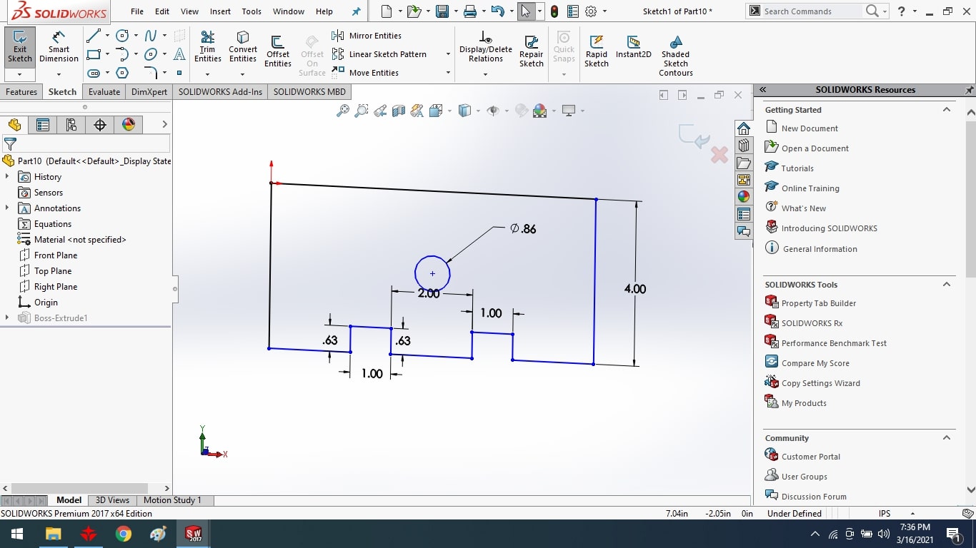
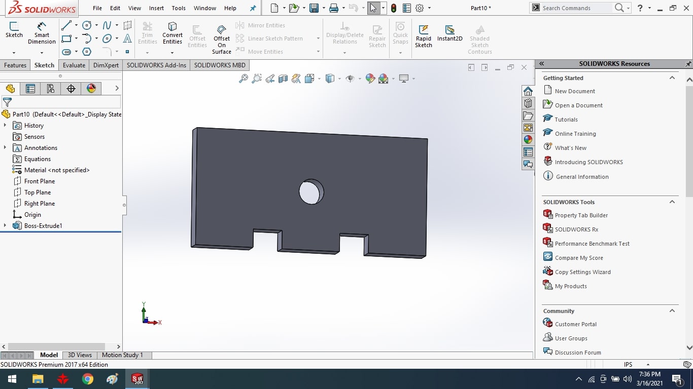
Using the line and circle tools, I sketched the top and bottom part's side supports.
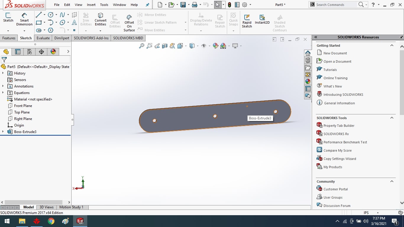
After that, I extruded the supports with the extrude boss tool.
I used a line and circle tool to design the top and side support of the desk, and a nut and bolt to connect the scissor.
After that, I extruded the supports with the extrude boss tool.<
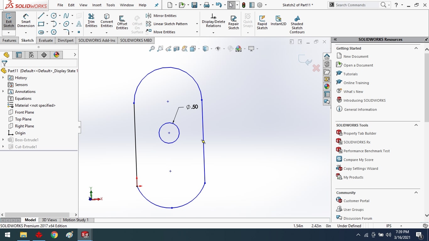
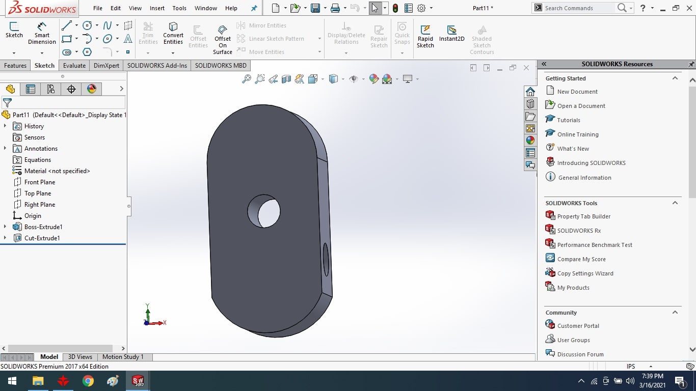
I used the line tool to sketch the scissor for my final project and to create the curve. To fix the scissor with nut and bolt, I've added a circle.
After that, I extruded the supports with the extrude boss tool.
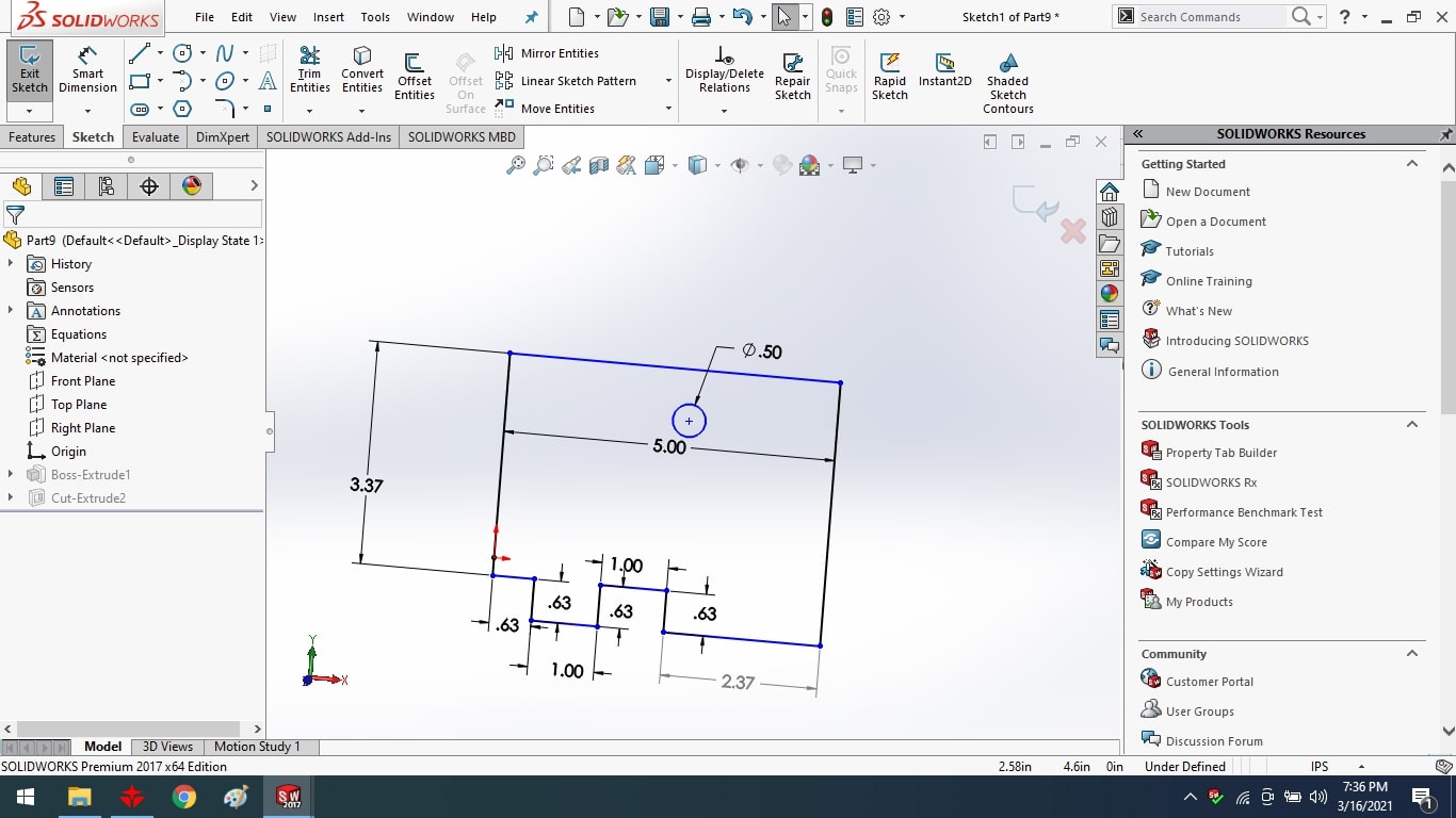
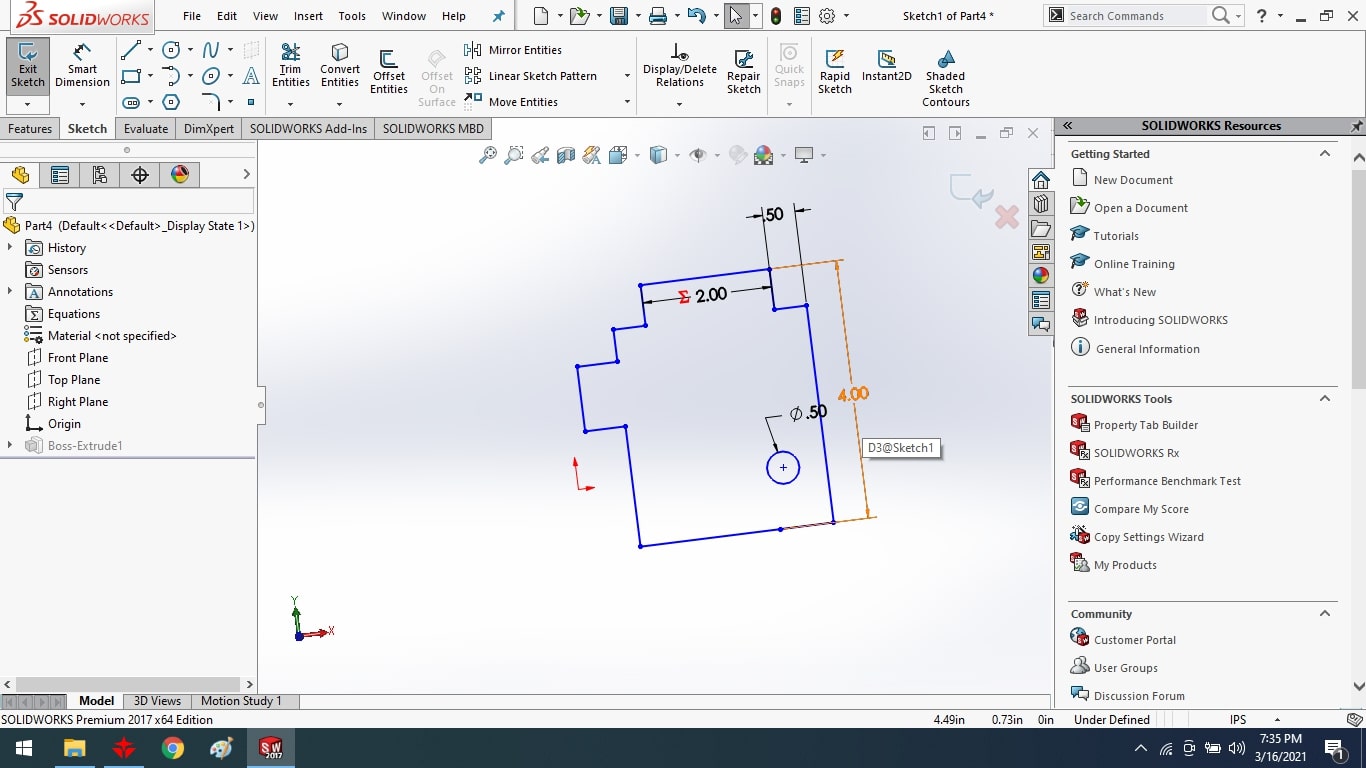
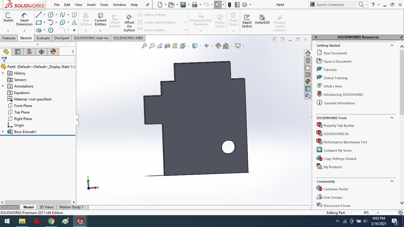
sketched the bottom surface support using line and circle tool.
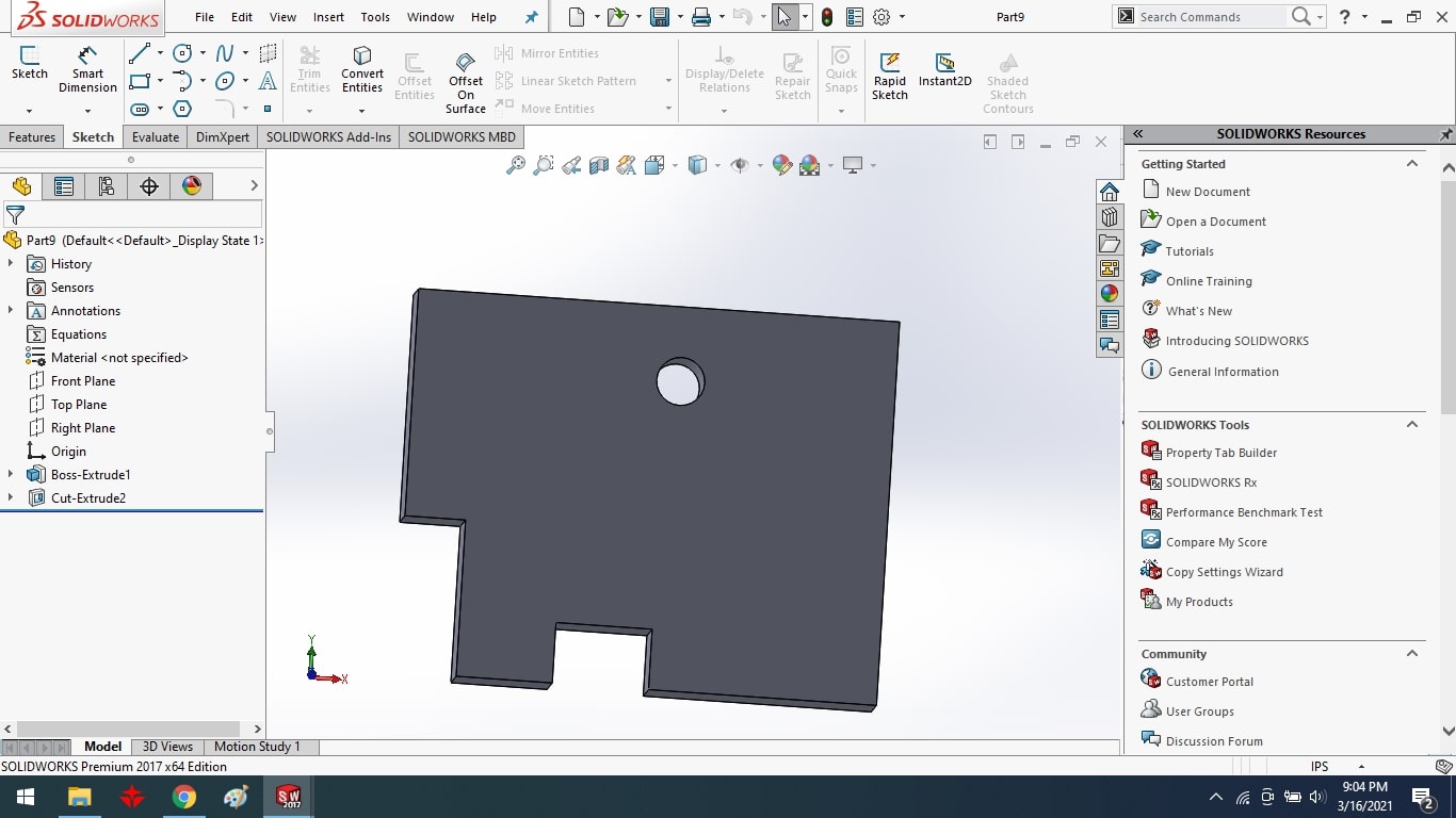
3D part of bottom surface support.
Then I drew a middle support to hold the motor in place on the desk surface..
After that, I extruded the supports with the extrude boss tool.
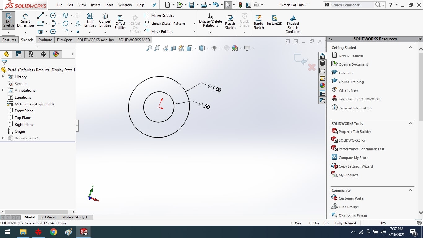
To fix the two middle scissors, I created a motor bush with a circle tool and the bush diameter is 25.4mm size.
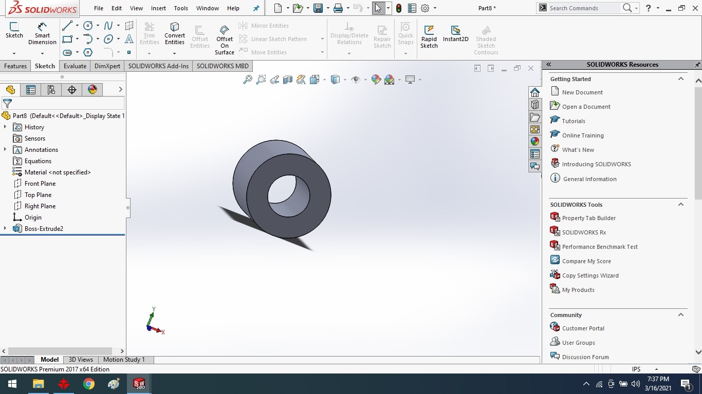
After that, I extruded the bottom part with the extrude boss tool.
I built the motor clip to help move the scissor by fixing it between the steel rod and the scissor.
After that, I extruded the motor clip with the extrude boss tool.
Assembled of Final Project Parts:
Merge all parts in assembly form.
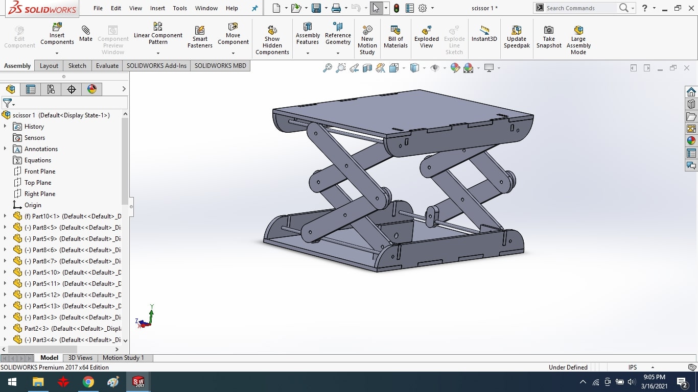
Final Result.
Solid work to DXF conversion:
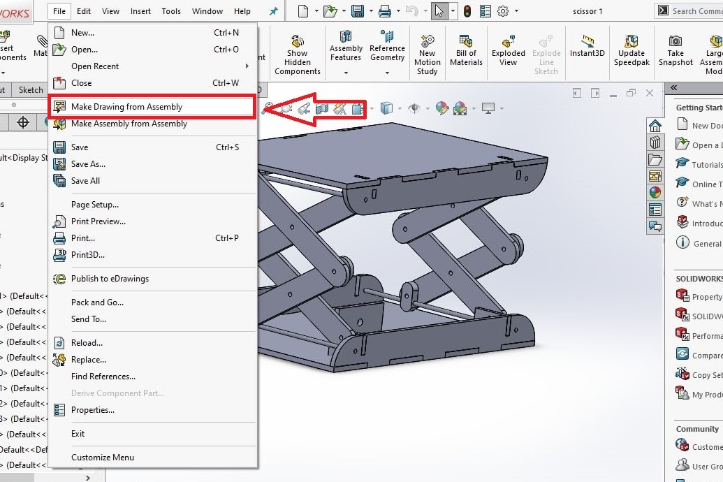
First, go to the menu>file>Make drawing from assembly.
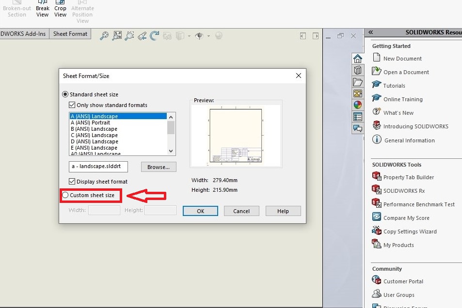
Then select the option of custom sheet size and click the ok button.
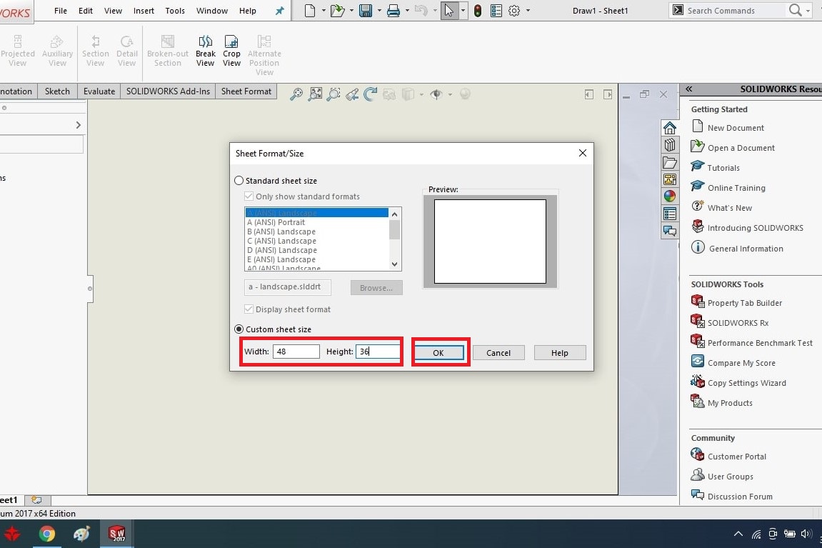
Then change the sheet size and click the ok button
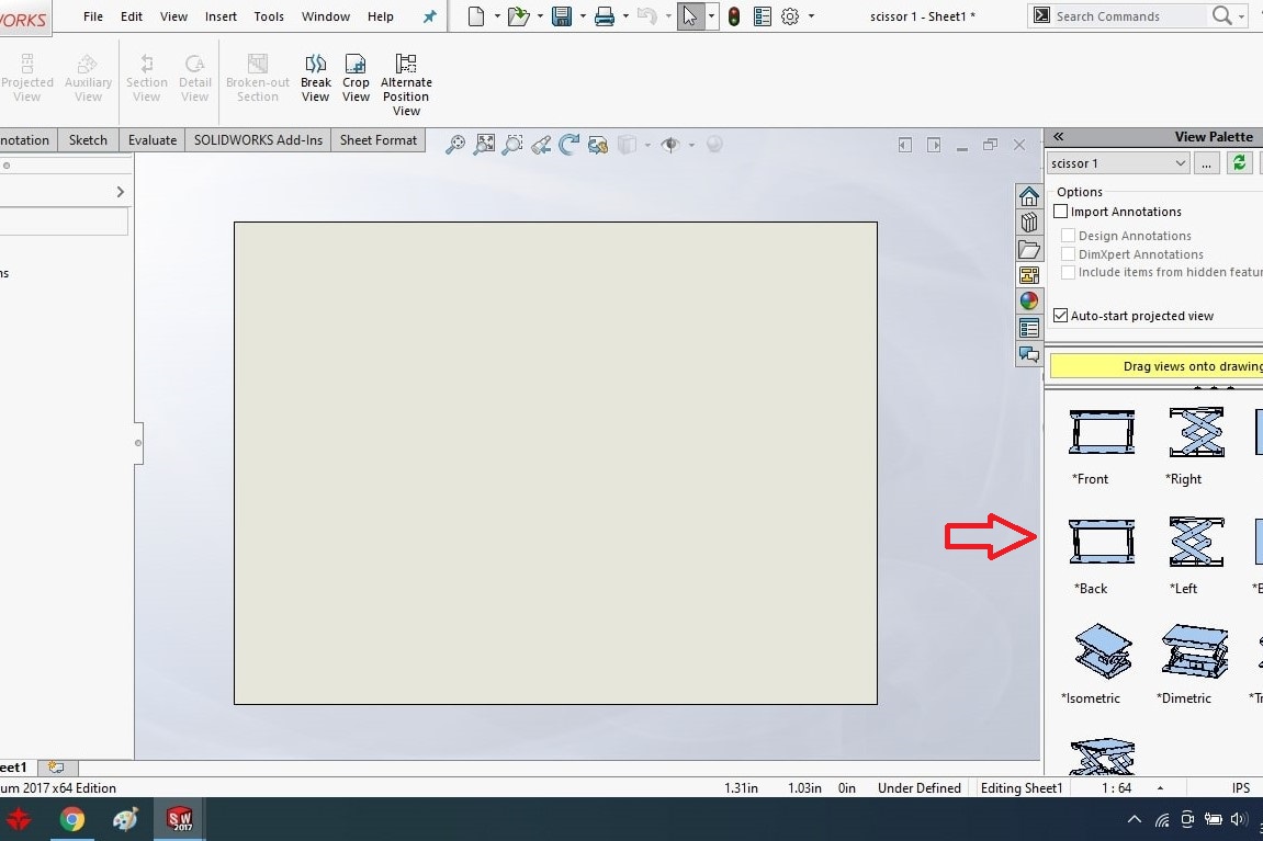
Then I can see my project assembly on the left side of the window.
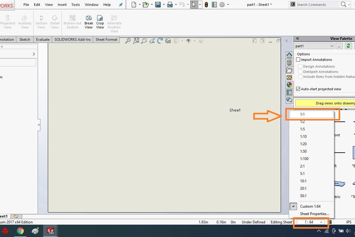
I have given scaling 1:1.
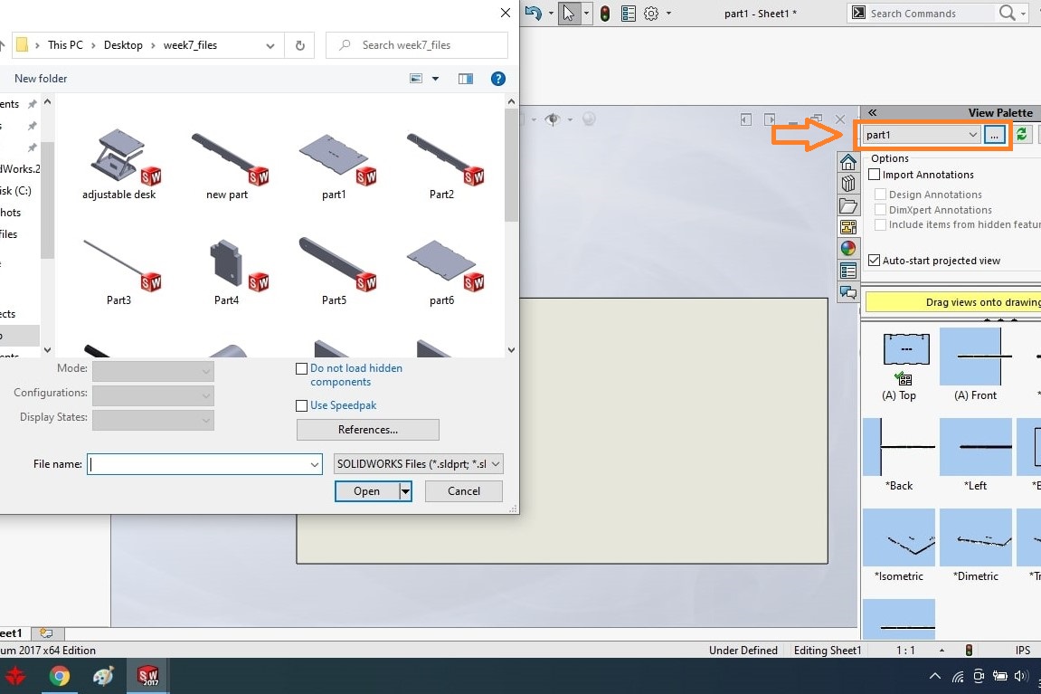
Then I have to import each part from the folder.
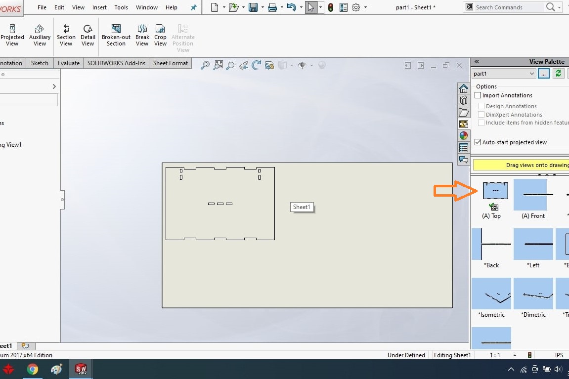
Drag each part from the left side window to the page.
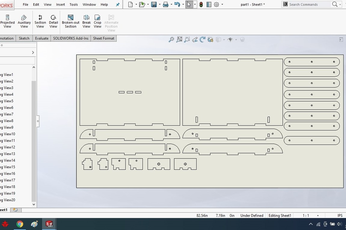
Complete all parts drag into the page which I want to do mill.
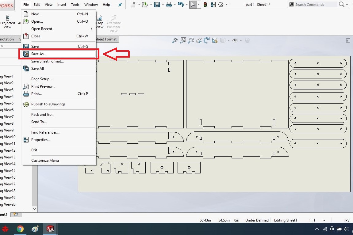
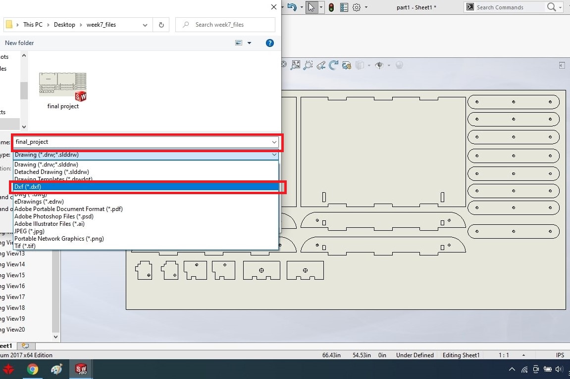
Save the file into the DXF format.
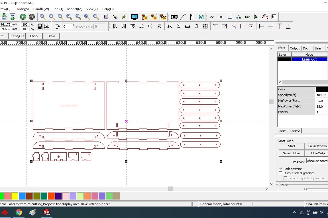
In this image, I have opened the file in RD work software.
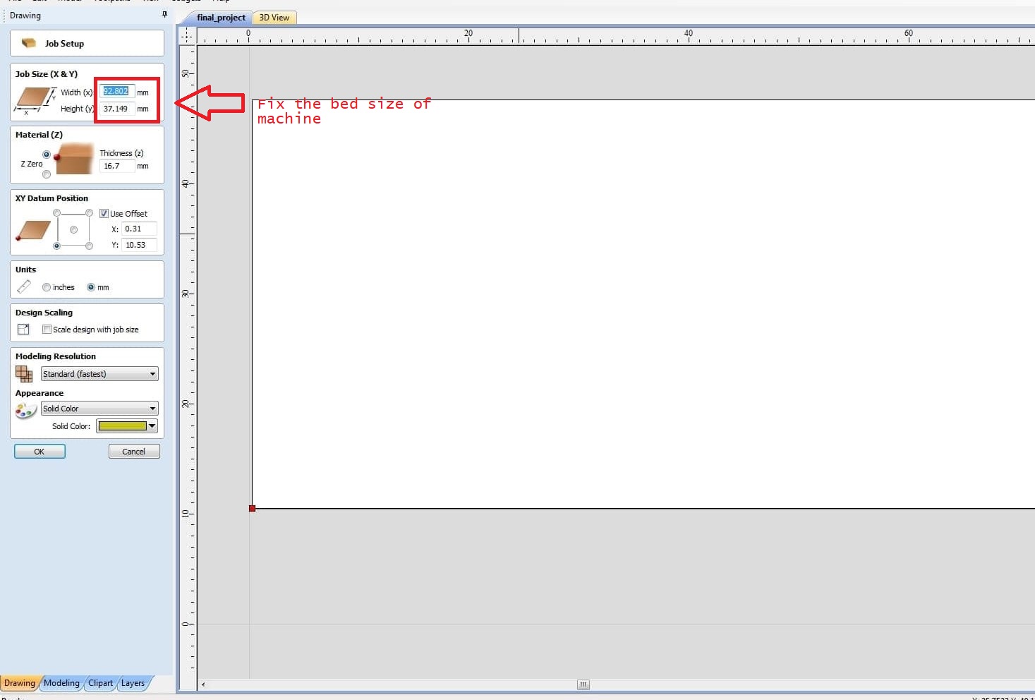
3D CNC -Working on Partworks 3d software:
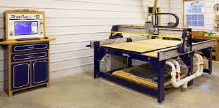
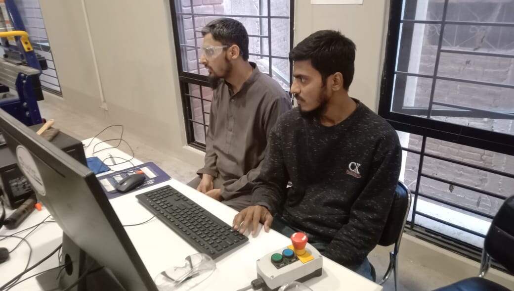
Working on Shopbot CNC machine guideline:
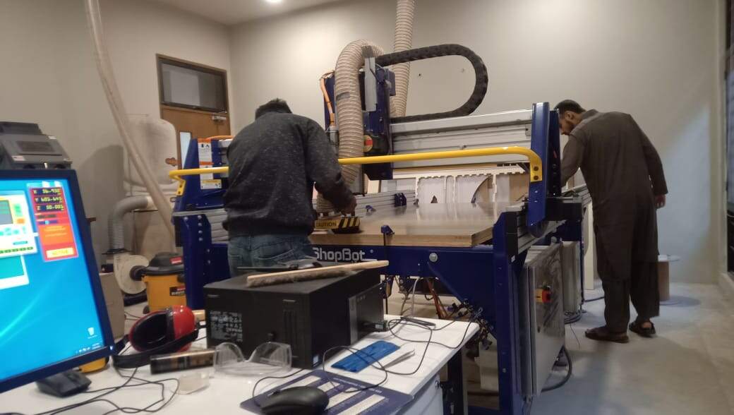
Step 1 Mounting material and tool on machine:
Step 2 Getting started with machine
Zeroing the table:
Starting a job:
Emergency stop:
There are three emergency stop buttons that one can use,
Material use with Shopbot CNC
They are capable of cutting 2D and 3D shapes in wood, foam, plastic, some non-ferrous metals, and a variety of other materials
Safety Measures:
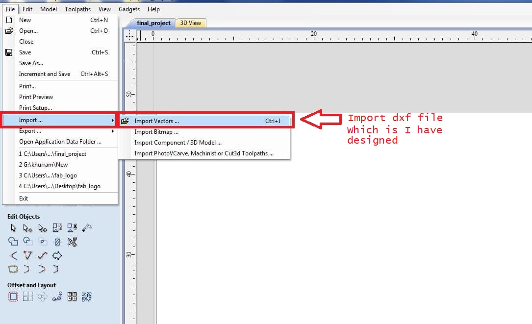
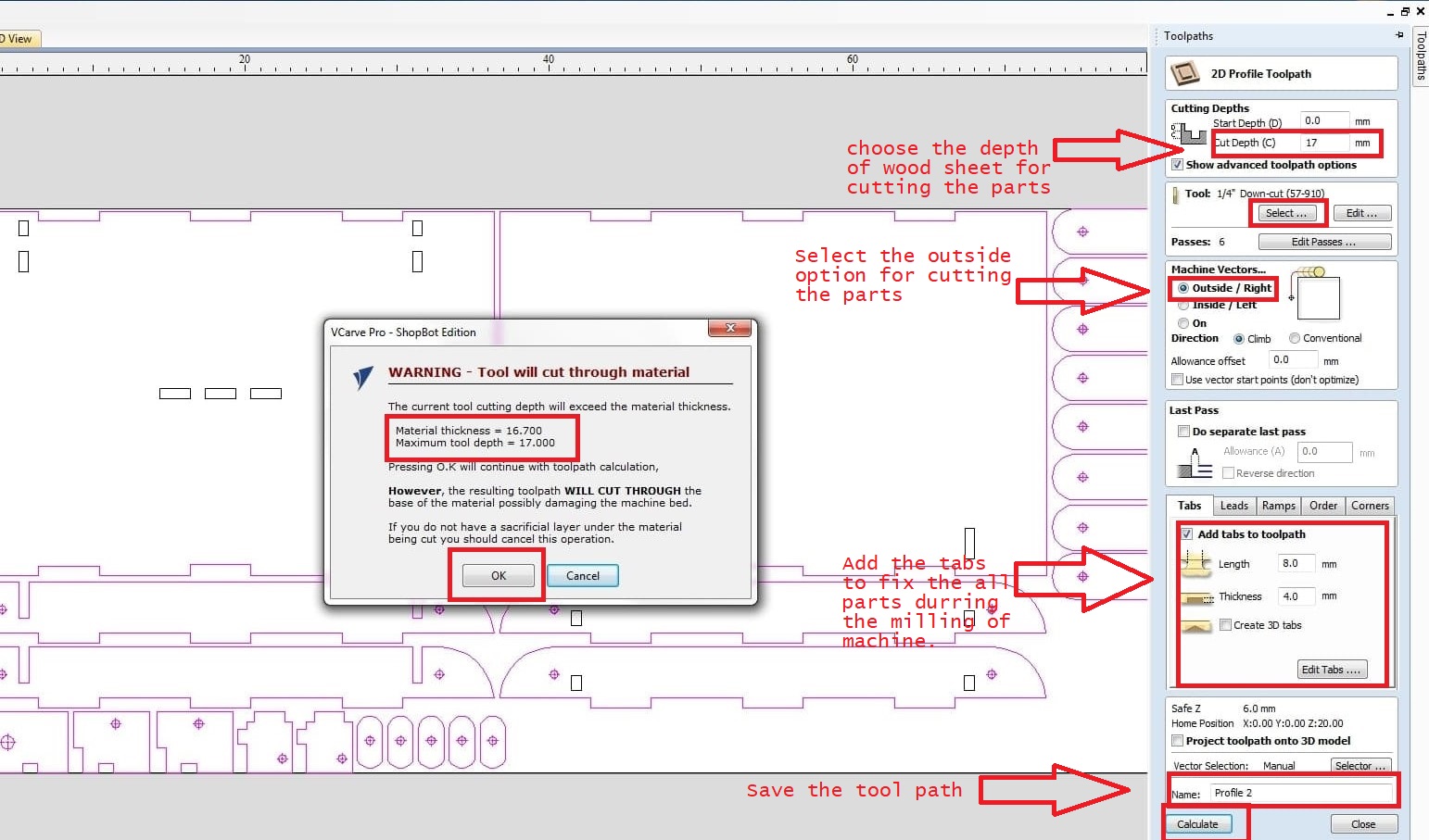
Tool path generation in V_carve pro:
importing that file in partworks
Selecting the profile and creating the fillets
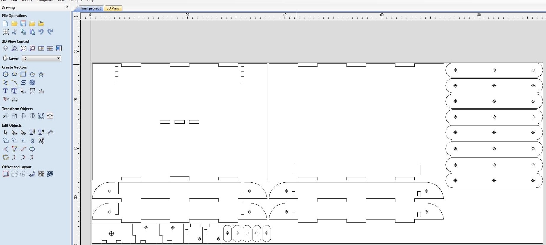
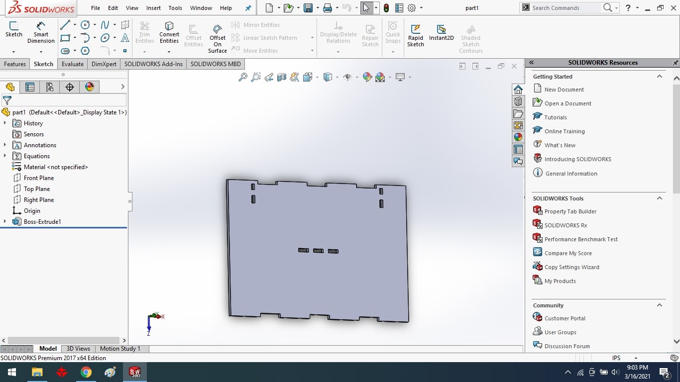
This is my final project parts.

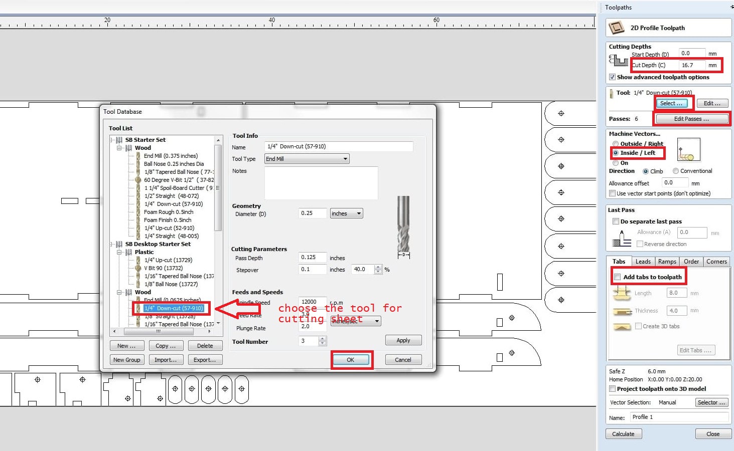
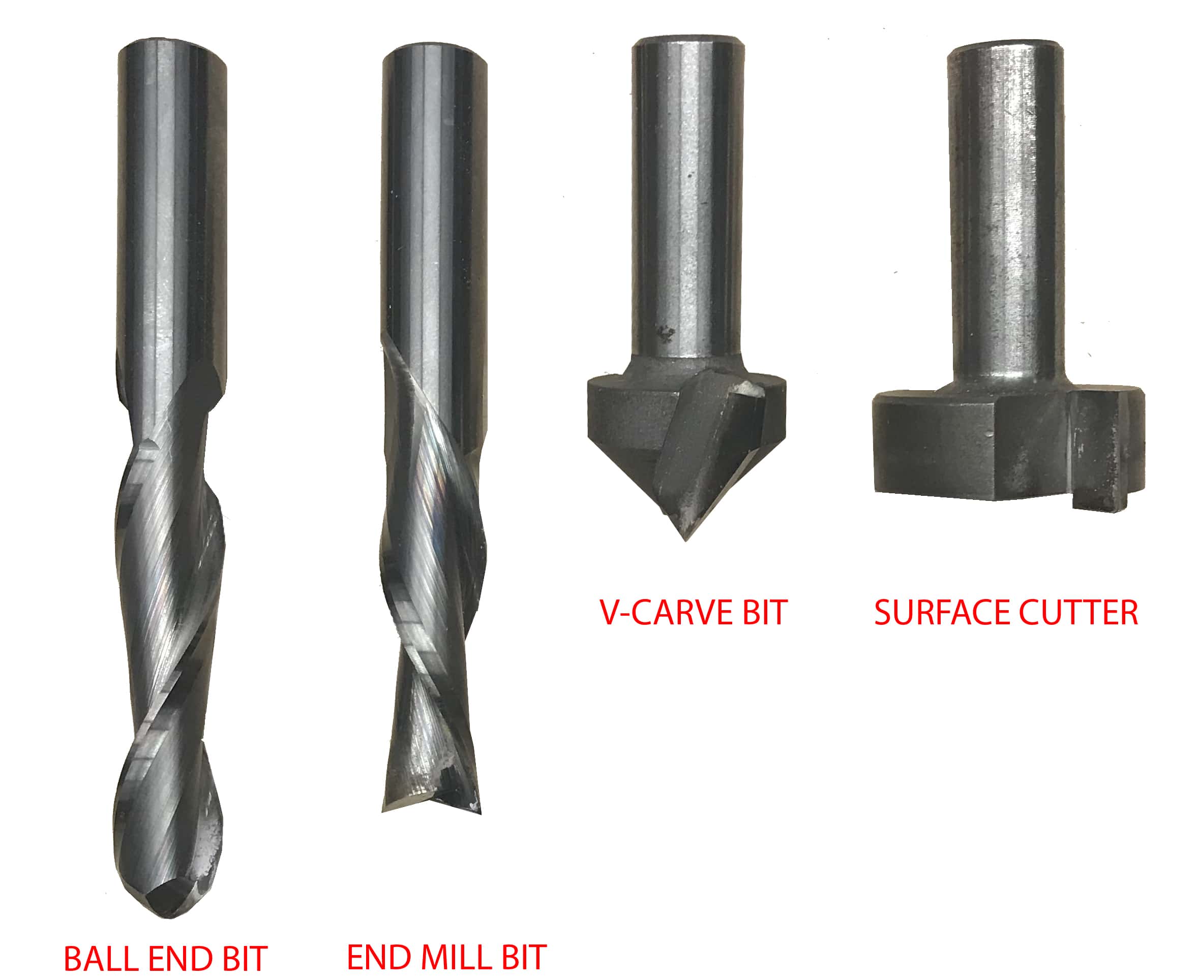
Creating the inside tool path selecting the tool for milling the tool selection is based on material and its thickness also on the size of your cut
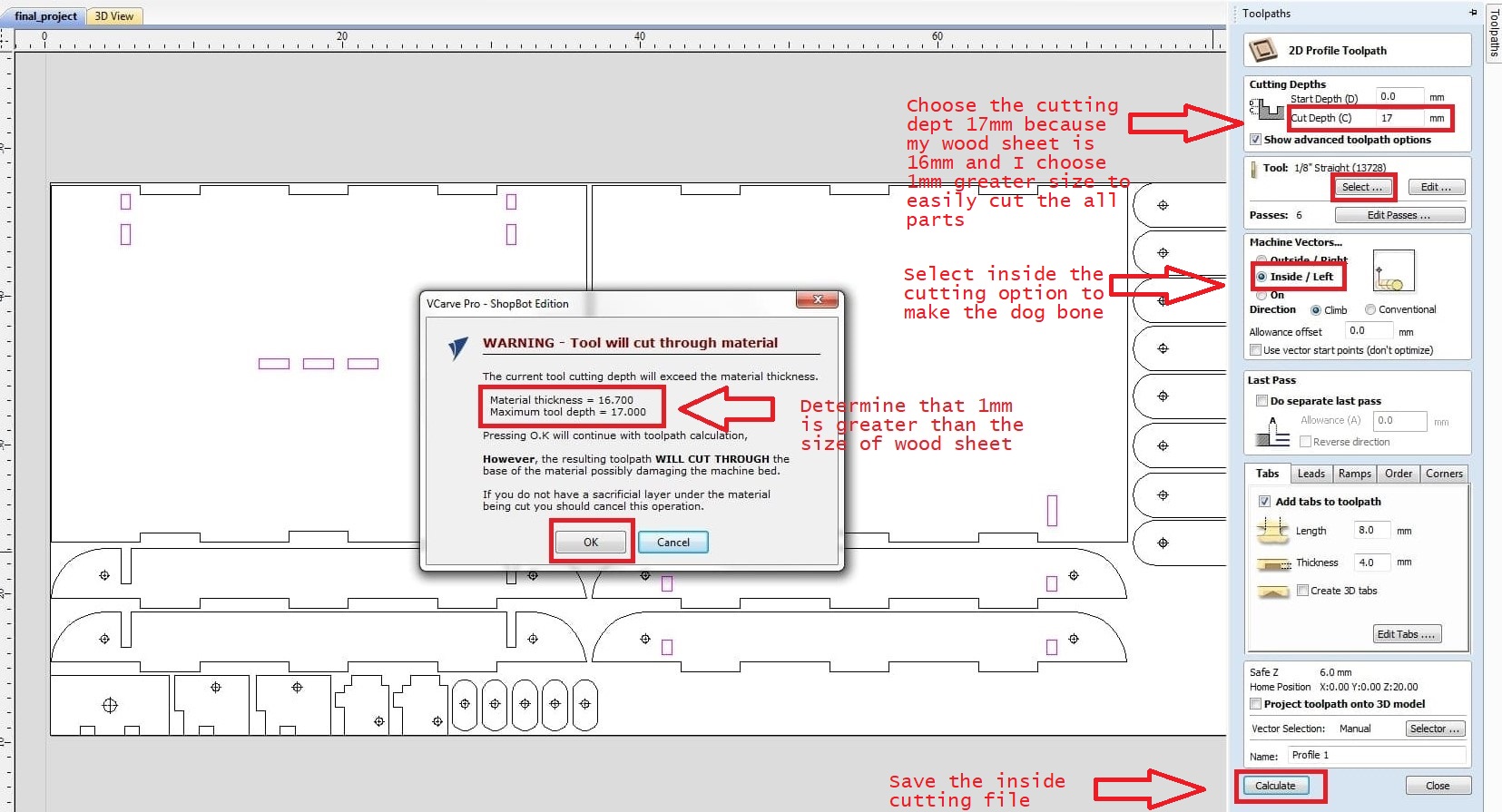
Once you set all this parameters you are done with tool path now just select the calculate to generate the tool path
CNC Milling:
For cutting my project, I use the chipbot material for sheet. To begin, I measure the thickness of the sheet with vernier caliper and place it on the machine, then fix the sheet with the clamp.
I start by changing the bit for inner side cutting and setting the machine's x,y,z axes, then giving over the inner cutting file and turning on the spindle to begin the job.
Set the machine's axis.
Change the bit for outer cutting.
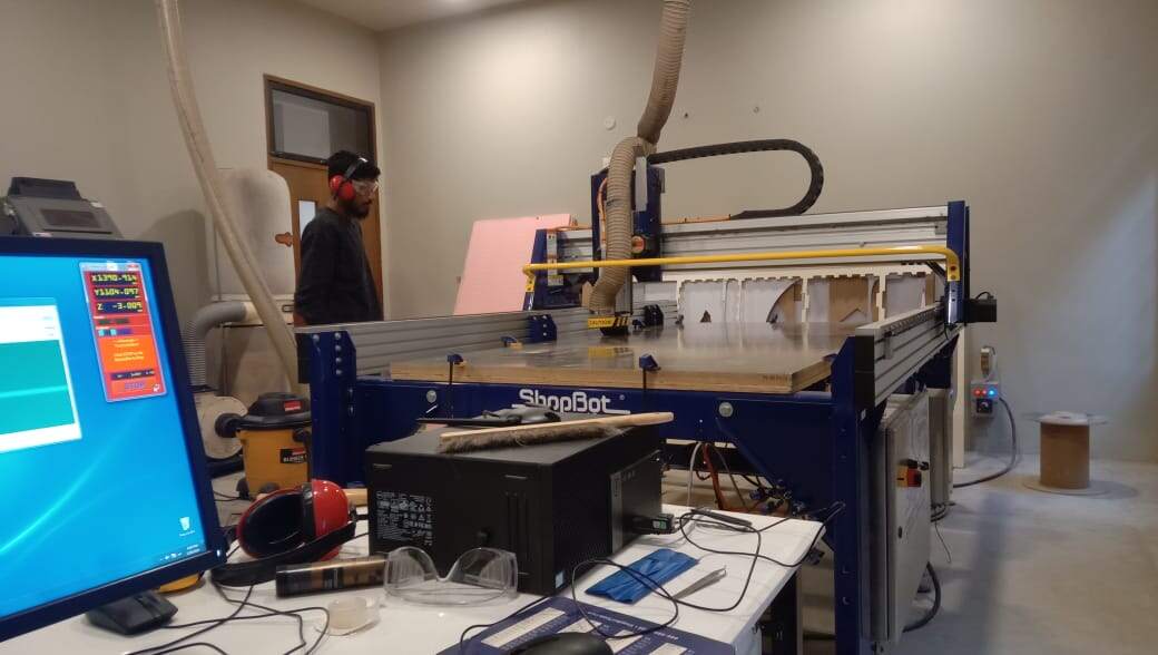
And keep a watch on how the machine works.My name is being milled on a machine.
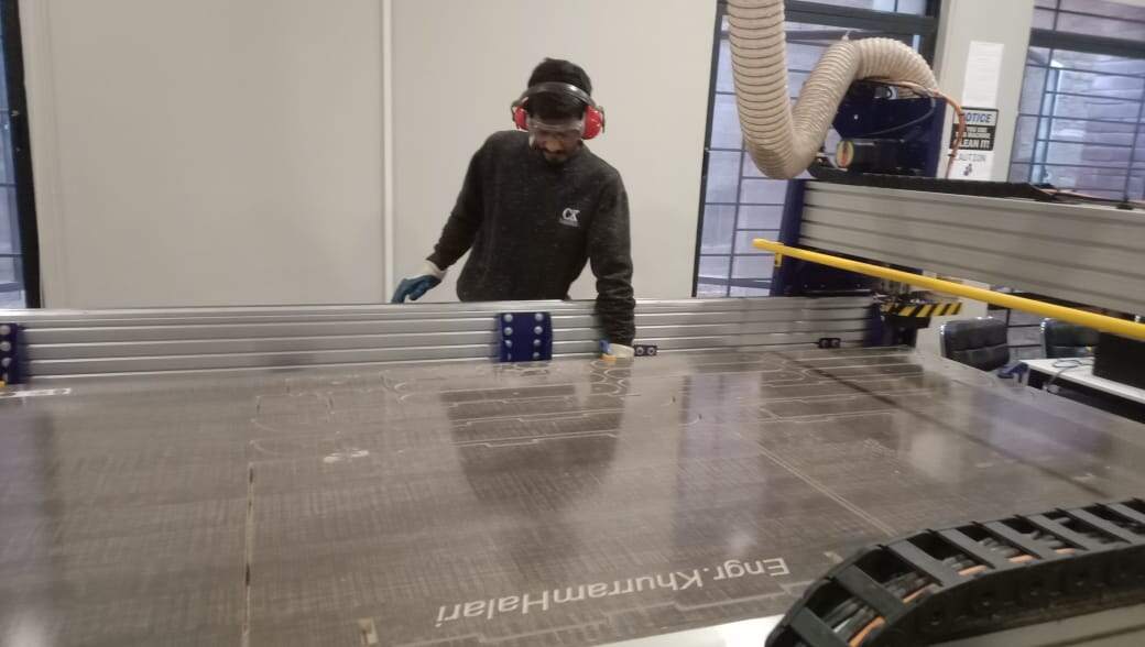
Remove the clamp after finishing all of the machine's jobs.
Final Result:
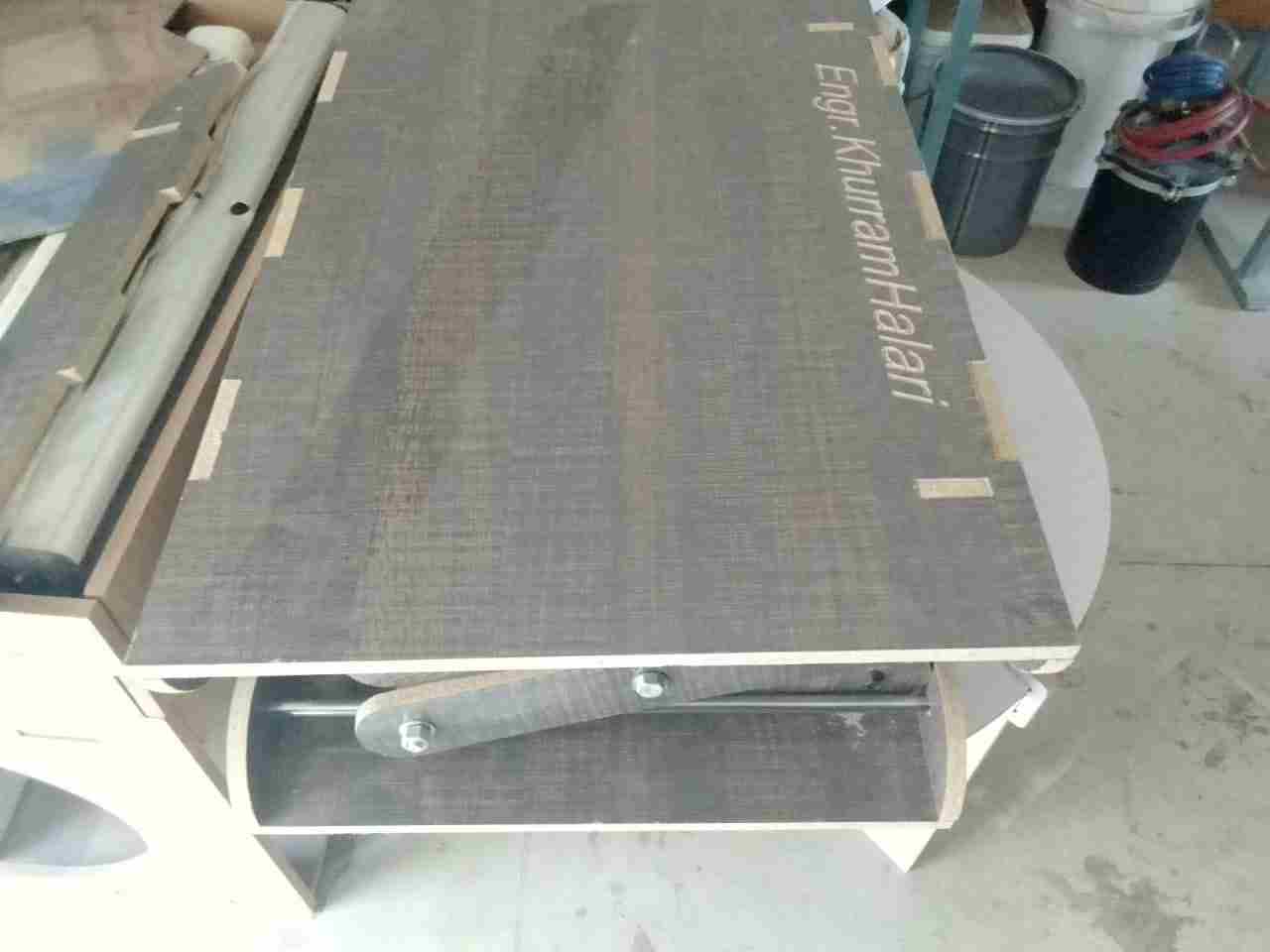
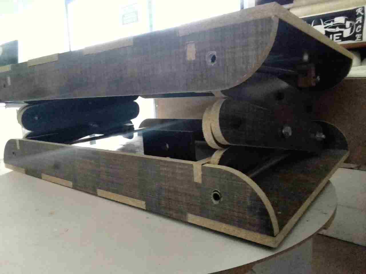
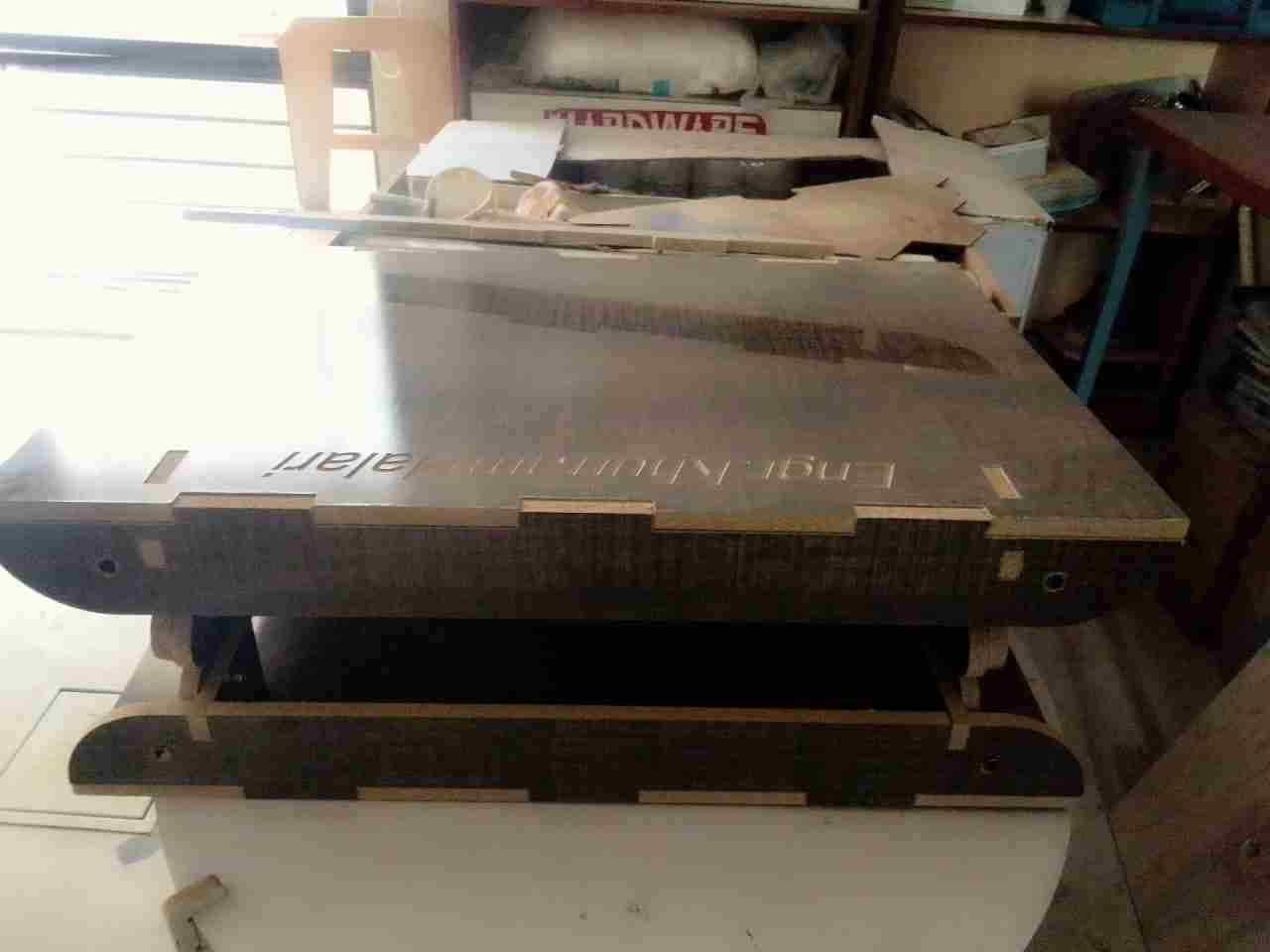
I LOVED WORKING WITH THE SHOPBOT.... CNC GIVE A LOT A POSSIBILITY TO CREATE FURNITURE, DESIGN & DECORATIONS PIECES.
Group Assignment
The group assignment of this week is we have to test run out, alignment, speeds, feeds, and toolpaths for your machine. For this we made a design in solid works and cut it in CNC.
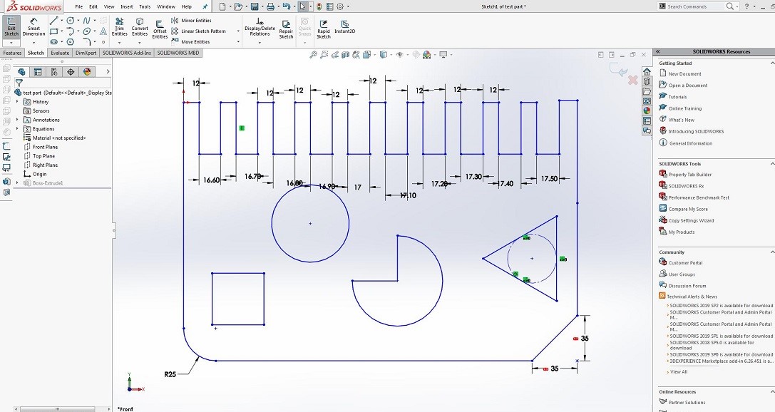
We save the file in a dxf format and open it in V carve pro to generate the tool paths.
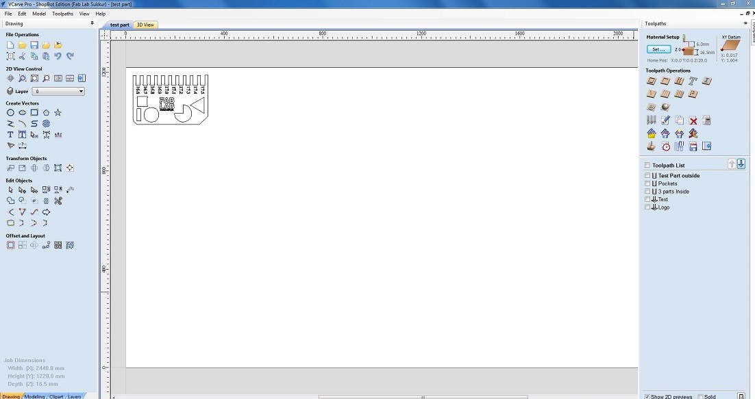
generationg toolpath for the cutting.
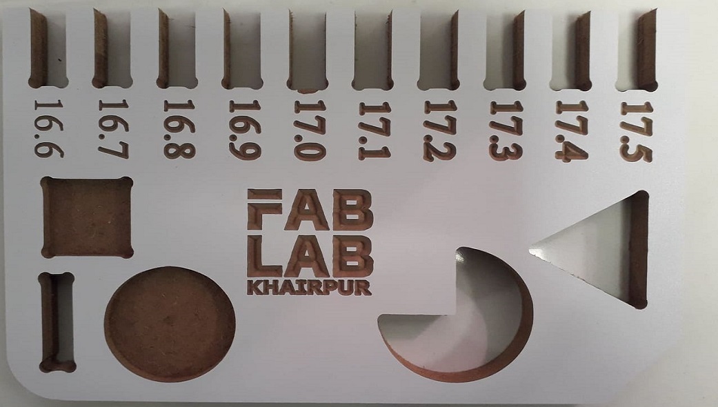
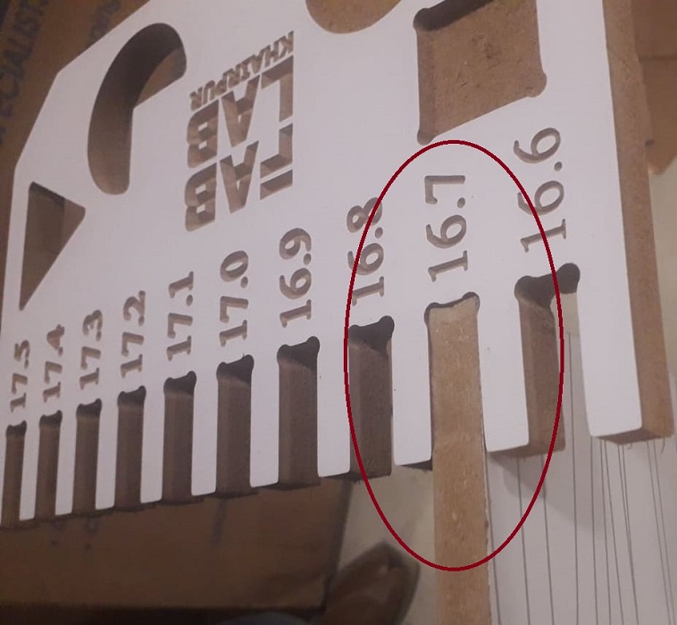
We have the MDF sheets in lab with thickness of 16.3mm. So we cutted part in that sheet, we used both outside cut and inside cut on different areas and also used pocket tool path you can also see in image and after cutting it was fixing in 16.7mm cutted area, we cutted this area with outside cut toolpath.
"Click here"to download all files of this week