BACK TO HOME PAGE
WEEK 8
EMBEDDED PROGRAMMING
WEEK ASSIGNMENTS:
Tasks for a week
environments as possible
Task: Group Assignment:
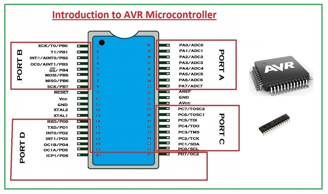
Introduction to AVR Microcontroller
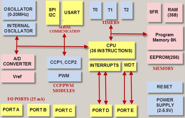
The microcontroller is the advanced version of microprocessors. It contains an on-chip central processing unit (CPU), Read-only memory (ROM), Random access memory (RAM), input/output unit, interrupts controller, etc. Therefore a microcontroller is used for high-speed signal processing operation inside an embedded system. It acts as a major component used in designing an embedded system Click. Where AVR microcontroller is an electronic chip manufactured by Atmel, which has several advantages over other types of the microcontroller. We can understand the microcontroller by comparing it with Personal Computer (PC), which has a motherboard inside it. In that motherboard, a microprocessor (AMD, Intel chips) is used that provides the intelligence, EEPROM, and RAM memories for interfacing to the system like serial ports, display interfaces, and disk drivers. A microcontroller has all or most of these features built into a single chip, therefore it doesn't require a motherboard and any other components, Click. AVR microcontroller comes in a different configuration, some designed using surface mounting and some designed using the whole mounting. It is available with 8-pins to 100-pins, any microcontroller with 64-pin or over is surface mount only.
CPU: The CPU has an 8 bit ALU with a status register, stack pointer, and 32 general-purpose registers. 8 GPR can be used as a 16-bit register; 3 of the double register as address pointer (X, Y, Z). The GPR is part of the SRAM and thus volatile, meaning they lose their content without power, and are not defined when power returns. Control Unit: The RISC command and control unit with program counter can treat most 16-bit commands (instructions) in one clock cycle. We reach near 16 million instructions per second ([MIPS]) Instructionspersecond#Millionsofinstructionspersecond_(MIPS)) with a 16 MHz crystal (about the speed of an INTEL 80386 in 1990). Click. Input/Output: Depending on the controller we get from one to four 8-bit GPIO ports, 8- and 16-bit timer/counter, a real-time clock (RTC), PWM outputs, external interrupts, serial interfaces (EIA232, I²C(TWI), SPI), analog to digital converter (ADC), USB. Memory: Three memory blocks are available. Non-volatile 16-bit Flash program memory, a little non-volatile 8-bit EEPROM, and the volatile 8-bit SRAM. We will look in detail at these memories in this chapter, Click. Programming logic: The controller memory (FLASH, EEPROM, fuse, and lock-bits) can be programmed and cleared over SPI (Serial Peripheral Interface) in-system (ISP).
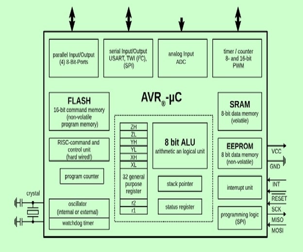
AVR's are available in many different housings and can use voltages from 1.8 V to 5.5 V. Apart from ISP they can be programmed using a bootloader (Arduino) or debugged over JTAG.
PIC Micro Controller
PIC is a Peripheral Interface Microcontroller that was developed in the year 1993 by the General Instruments Microcontrollers. It is controlled by software and programmed in such a way that it performs different tasks and controls a generation line. PIC microcontrollers are used in different new applications such as smartphones, audio accessories, and advanced medical devices. There are many PICs available in the market ranging from PIC16F84 to PIC16C84. These types of PICs are affordable flash PICs. Microchip has recently introduced flash chips with different types, such as 16F628, 16F877, and 18F452.
PIC Microcontrollers Architecture
The PIC microcontroller is based on RISC architecture. Its memory architecture follows the Harvard pattern of separate memories for program and data, with separate buses.
Task:01 To program the echo hello-world board:
On week 7 , we learn how to make a electronic circuit board.Now we need to program according to our requrements.

EMBEDDED SYSTEM:
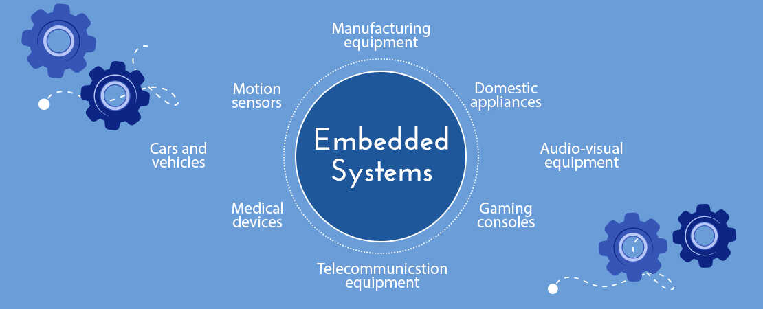
An embedded system is a controller programmed and controlled by a real-time operating system (RTOS) with a dedicated function within a larger mechanical or electrical system, often with real-time computing constraints. It is embedded as part of a complete device often including hardware and mechanical parts. Embedded systems are commonly found in consumer, industrial, automotive, medical, commercial and military applications.
ATTINY44:
ATtiny (also known as TinyAVR) are a subfamily of the popular 8-bit AVR microcontrollers, which typically has fewer features, fewer I/O pins, and less memory than other AVR series chips. ATTINY 44 is 16 pin 8bit microcontroller.The ATtiny44 is a high-performance, low-power Microchip AVR RISC-based CMOS 8-bit microcontroller.It combines 4KB ISP flash memory, 256-Byte EEPROM, 256B SRAM, 12 general purpose I/O lines . The ATtiny44 consistof 32 general purpose working registers, an 8-bit timer/counter with two PWM channels, a 16-bit timer/counter with two PWM channels,internal and external interrupts, an 8-channel 10-bit A/D converter and a programmable gain stage (1x, 20x) for 12 differential ADC channel pairs. It has a programmable watchdog timer with internal oscillator.The a internal calibrated oscillator and three software selectable power saving modes makes it suitable for small embedded products . By executing powerful instructions in a single clock cycle the device achieves throughputs approaching 1 MIPS per MHz .It also balance power consumption and improve processing speed.
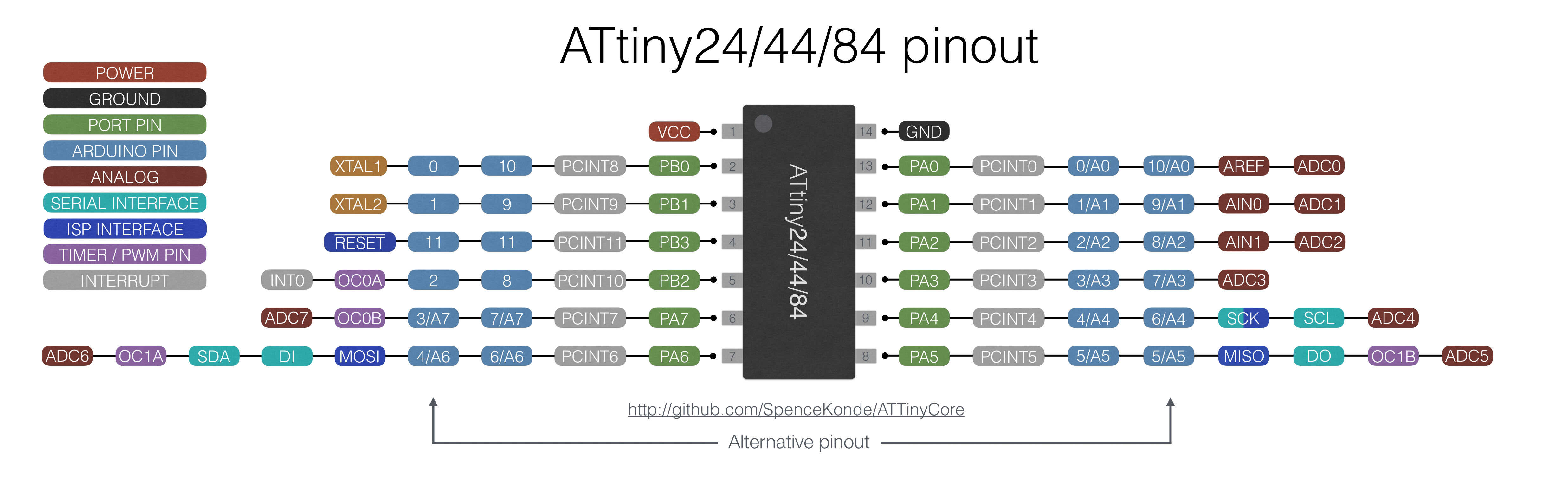
Datasheet is the biography and manual of any electronic component. They explain exactly what a component does and how to use it. Before you start doing anything or even designing any circuit, looking at the datasheet is crucial. It holds important information like Power supply requirements, Pins Configurations and descriptions, Electrical ratings and Schematic of the IC circuit.
First of all, In the begining, you can see generally the features, and from the most important features: The memory, Number of pins and Operating voltage and others.
PIN DESCRIPTIONS
VCC
Supply voltage
GND
Ground
Port B (PB3...PB0)
Port B is a 4-bit bi-directional I/O port with internal pull-up resistors (selected for each bit). As inputs, Port B pins that are externally pulled low will source current if the pull-up resistors are activated.so we don't need to add a pull-up resistor externaly for button's and other purpose.
RESET
Reset input. A low level on this pin for longer than the minimum pulse length will generate a reset, even if the clock is not running.a reset will just reset the programm that currently runnig .
Port A (PA7...PA0)
Port A is a 8-bit bi-directional I/O port with internal pull-up resistors (selected for each bit). As inputs, Port A pins that are externally pulled low will source current if the pull-up resistors are activated
PROGRAMMING ATTINY44 WITH ARDUINO IDE:
For Programming Echo Hello Board I mainly used Arduino IDE
ARDUINO
Arduino is an open-source electronics platform based on easy-to-use hardware and software. we can tell your board what to do by sending a set of instructions to the microcontroller on the board.
To do so you use the Arduino programming language (based on Wiring), and the Arduino Software (IDE), based on Processing.I felt more easy to use Arduino since i am new to programming. The Arduino system is based on the avr-gcc compiler and makes use of the standard AVR libc libraries, which are open-source C libraries, specifically written for Atmel hardware.
By default the arduino software doesnt contain Attiny 44 chip librarys. We need to include the deatils manually.
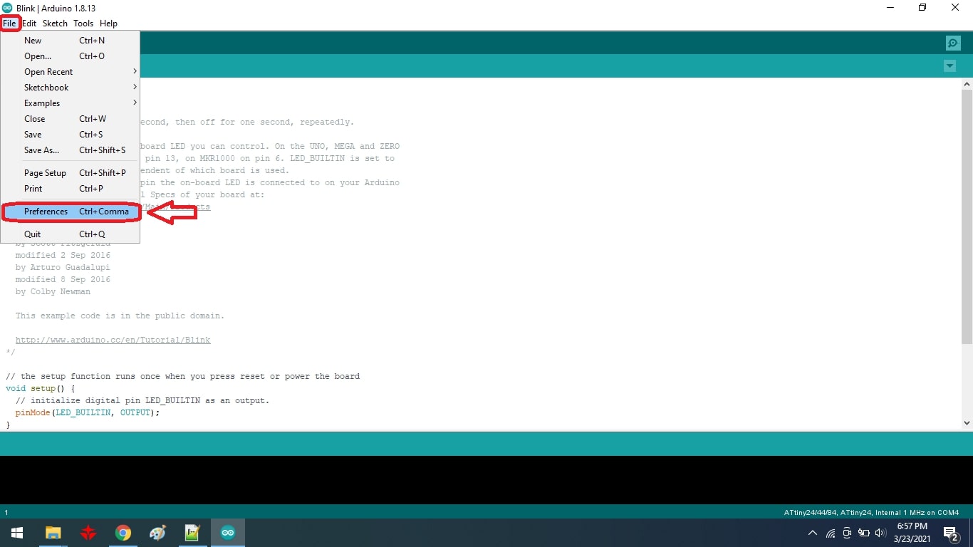
Install and Open Arduino IDE
Open File.Select Preference
Add URL in addtional board manager
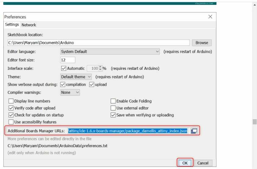
After adding the URL
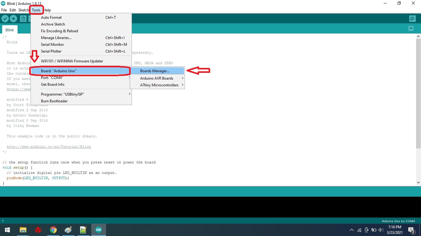
open Board Manager by clicking Tools > Board >Board Manager
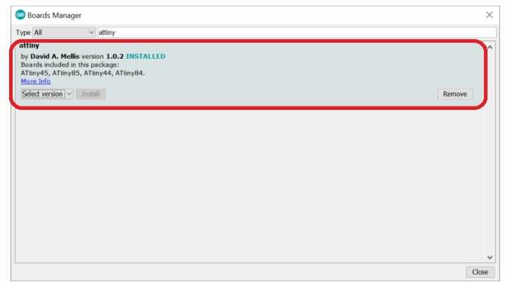
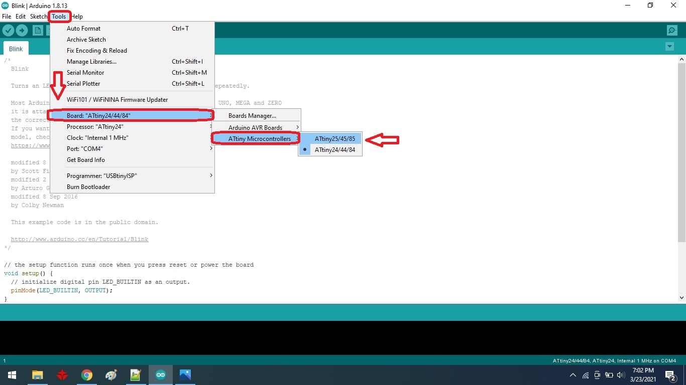
Search for ATtiny44 in the Window and select ATtiny44 under the ATtiny Microcontrollers in board Selection.
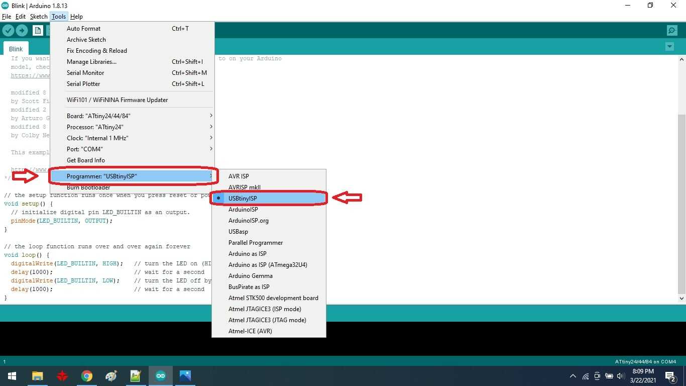
Select appropriate Clock and Programmer.
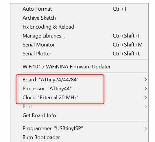
We are using Fab ISP to programme the Hello-Echo board so Select the Programmer as USBtinyISP.
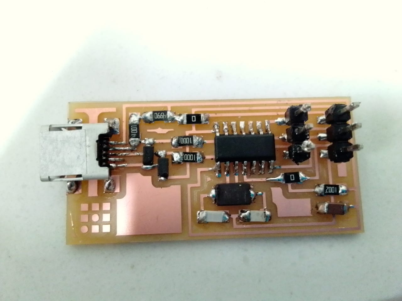
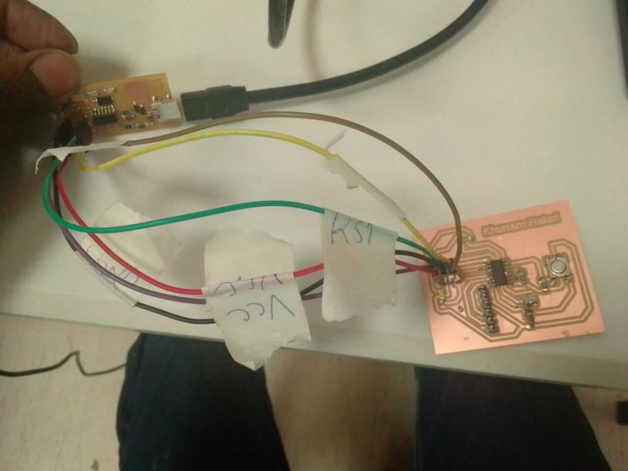
I used my fab isp which was made in electronic production week for programming the hello board.
Now we can programm the hello board
ARDUINO CODE:
                        void setup() {
                          // put your setup code here, to run once:
                          pinMode (8, OUTPUT);}


                          void loop() {
                            // put your main code here, to run repeatedly:

                            digitalWrite (8 , HIGH);
                            delay (100);
                            digitalWrite (8 , LOW);
                            delay (100);}
    After adding push button
    void setup() {

        pinMode (7, INPUT);
        pinMode (8, OUTPUT);    //set 8 as output (LED)
    }

     void loop(){

        int ButtonData = digitalRead(7);    //store 7 value to ButtonData variable

        if(ButtonData == HIGH)                //check the ButtonData is HIGH (HIGH means button is pressed)
            {
                digitalWrite(8,LOW);


            }
        else
            {
                digitalWrite(8,HIGH);
            }

     }
PROGRAMMING ATTINY44 USING ATMEL STUDIO:
Studio 7 is the integrated development platform (IDP) for developing and debugging all AVR® and SAM microcontroller applications. The Atmel Studio 7 IDP gives you a seamless and easy-to-use environment to write, build and debug your applications written in C/C++ or assembly code. It also connects seamlessly to the debuggers, programmers and development kits that support AVR® and SAM devices.
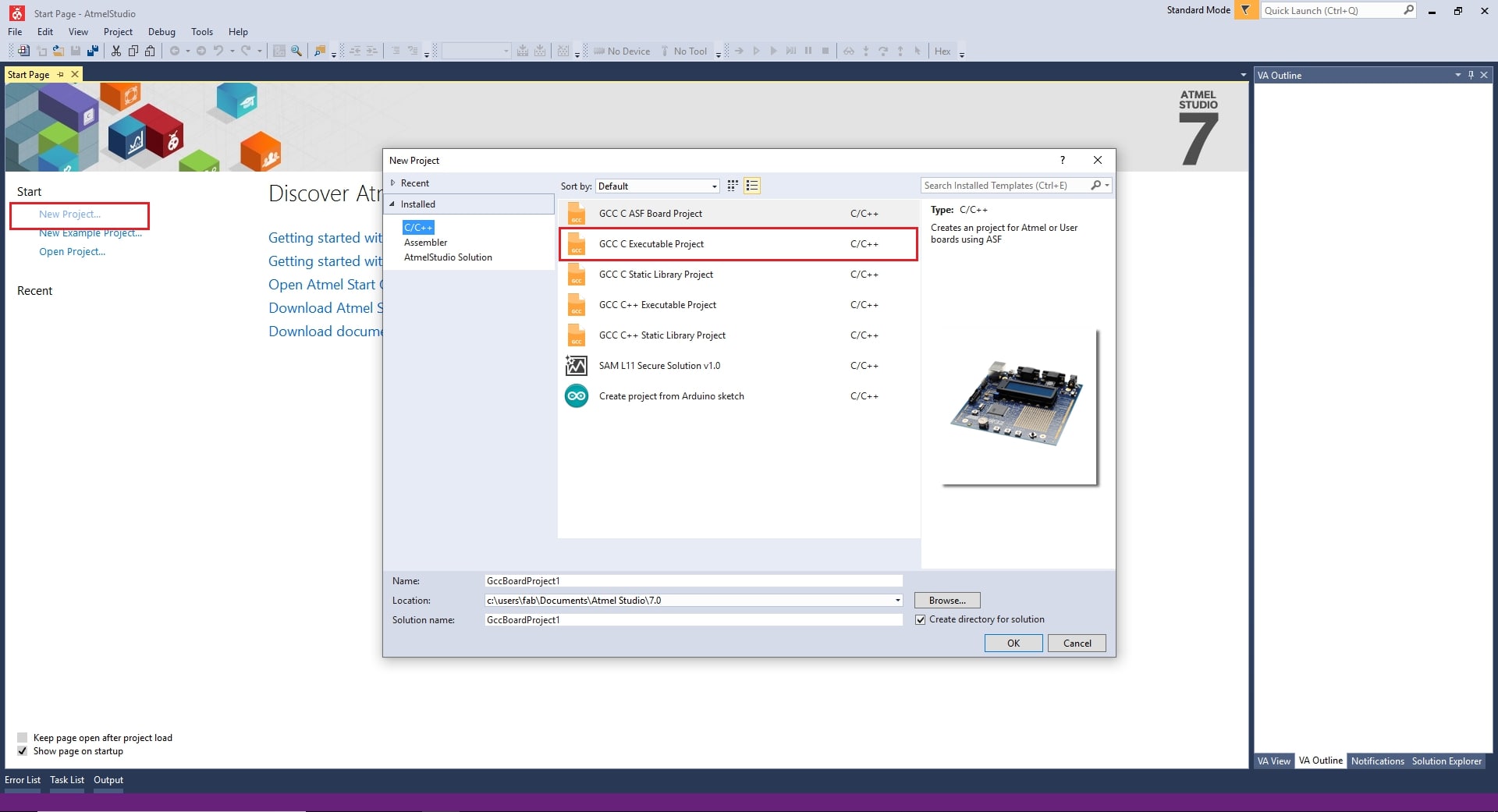
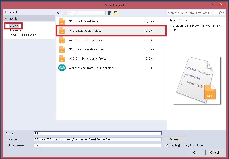
For programming first install and open ATMEL STUDIO. Click "New Project" and srlect"GCC C Exictable project". Click ok to confirm the selection
For programming first install and open ATMEL STUDIO. Click "New Project" and select"GCC C Exictable project". Click ok to confirm the selection
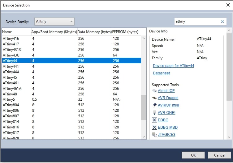
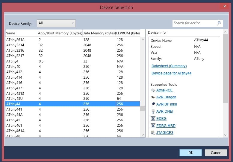
Now you can see the following window. Select device famiy as Attiny and select Attint 44. Click ok to confirm the operation.
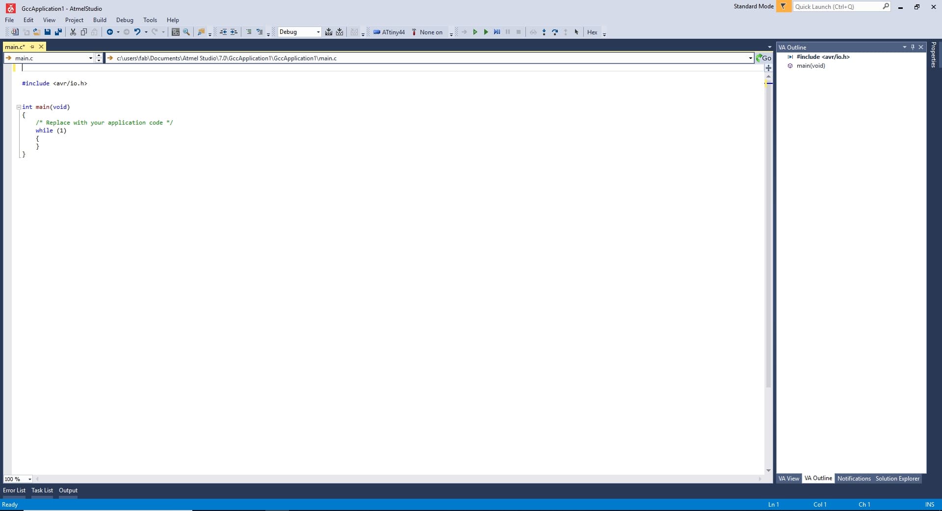
Now you will get a window.
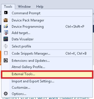
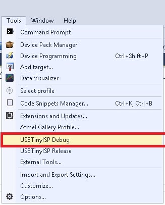
Now we need to setup some parameters for usbtiny debugging. For that Go to "Tools" and Select "External Tools."
Add following details to the box:
DEBUG VERSION:
Title:- USBTiny ISP Debug
Command :- avrdude.exe
Arguments :- -c usbtiny -p attiny44 -U flash:w:$(ProjectDir)Debug\$(TargetName).hex:iclick apply and ok to save the tool.
RELEASE VERSION
Title:- USBTiny ISP Release.
Command :- avrdude.exe
Arguments :- -c usbtiny -p attiny44 -U flash:w:$(ProjectDir)Release\$(TargetName).hex:iclick apply and ok to save the tool.
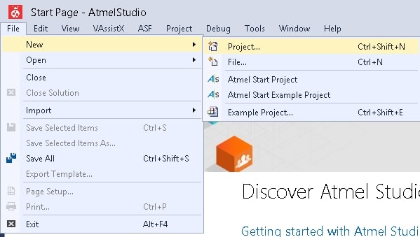
Start a Project by clicking File >> New >> Project
Now select C/C++ as language and Template as GCC C Executable Project give a name and click OK.
Then Select the Target Microcontroller , in here we have ATtiny44.
#define F_CPU 20000000UL //Clock 20-Mhz #include <avr/io.h> int main(void) { DDRA |= (1 << 8); // Set PA2 as OUTPUT for Red led DDRA &= ~ (1 << 7); //Set PA2 as INPUT for Button while (1) { if (PINA & (1 << 8)) //check whether the button pressed or not { PORTA = PORTA | (1 << 8); // Turn on WHITE led } else { PORTA &= ~(1 << 8); // Turn on WHITE led } }
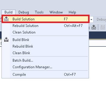
For Uploading code first we need to build/compile it by using Build > Build Soution
After the compailation we need to flash the code in to our board
The output is same as the Arduino.by clicking the button to flash the leds.
"Click here"to download all files of this week