10. Input devices
This week we worked on sensors as Input devices.
Group assignment of this week is to probe an input device’s analog levels and digital signals.
1st trial
In Saturday local session, we tried to prove analog levels and digital signals about Natsuka-san’s load cell sensor by using an Oscilloscope.
When we tried measuring we found that probes connected to the board also gave certain “load” to the sensor.
Because of that, Oscilloscope showed no changes in its screen even though we put something to measure its weight.
Due to time constrains, we gave up the measuring that day.
We will complete the group assignment in other day.
2nd trial
After week 13’s assignments completed, we tried again.
This time, we used a LED light and a potentiometer.
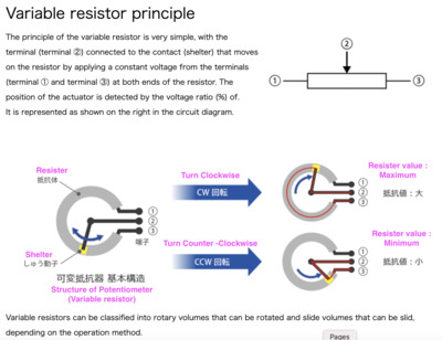
Potentiometer
A potentiometer is a three-terminal resistor with a sliding or rotating contact that forms an adjustable voltage divider.
In terms of the Group assignment - Potentiometer provide us digital signals. We could check digital signals from potentiometer, in green blocks of the oscilloscope. - LED provide us analog levels. We could check analog levels from LED, in yellow line of the oscilloscope.
We probed above inputs in a Oscilloscopes
-
Calbing t3216 breakout board, LED and Potentiometer
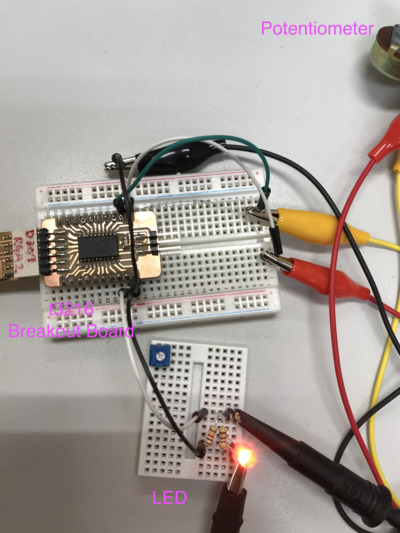
- GND and PA3 connect to LED
- GND, VCC and PA4 connect to Potentiometer
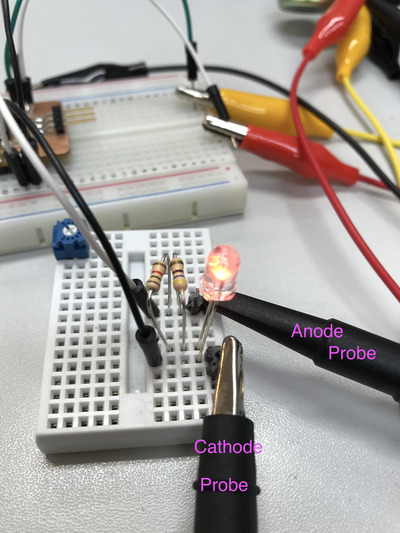
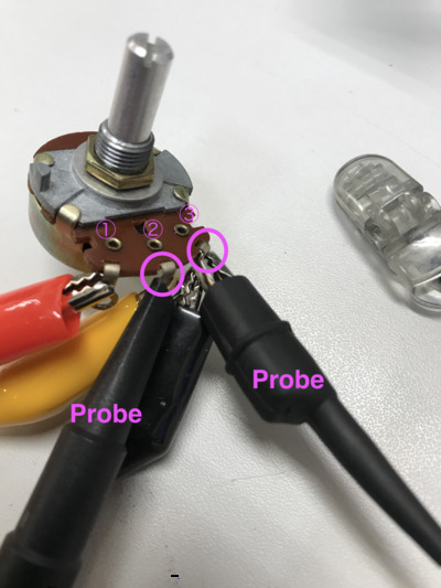
Analog levels measure between Cathode and Anode
Rotated potentiometer left to right clockwise to adjust levels of resister.
Digital Signals measure by middle terminal and right terminal
Rotated potentiometer left to right clockwise to adjust levels of resister. Brightness of LED changed from High to Low.
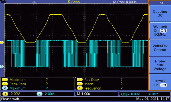
Oscilloscope
- Yellow line shows Analog levels of LED Move from lowest(High brightness) to highest(Low brightness) smoothly
- Green blocks show Digital signals of potentiometer Between lowest and highest, observed changes of intensity of vertical lines.
Code used
Arduino Codes:
TestAnalogInputLED.ino
const int PA4 = 0;
const int PA3 = 16;
int p1 = 0;
void setup() { Serial.begin(115200); pinMode(PA4, INPUT);
pinMode(PA3, OUTPUT);
}
void loop() { p1 = analogRead(PA4); Serial.println(“p1:PA4: “); Serial.println(p1);
int intensity = map(p1, 0, 1024, 0, 255);
analogWrite(PA3, intensity);
delay(10);
}