Week 14 : Interface & Application Programming

☛ Individual Assignment

☐ 1. Write an application that interfaces a user with an input & / or output device that you made

☛ Group Assignment

☐ 2. Compare as many tool options as possible


☛ MIT Inventor App


Last week I made an application to control motors through bluetooth, by makking an application with MIT Inventor app, the ressources I used and the process I followed are detailed in Week 13 - Networking and Communication. This week I will try to communicate from the arduino to the application.

Sample.img

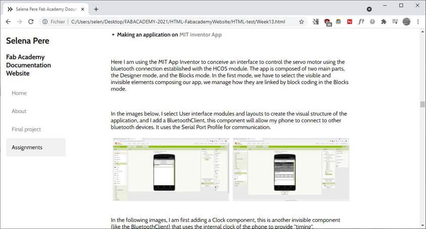
Using this application I can control the Labyrinth board, which is controlling 2 servo motors, here is a test of the board I made with the application made on MIT App Inventor :


☛ How to make a Drawing application using Arduino and Processing (?)


This week I will try to make a drawing application to use with the "Blow controller". I have not a clear idea of how to do that, and I didn't find targeted ressources.
I will first mkae a sketch on processing allowing to draw with the mouse, then I will try to control this sketch with a joystick plug to the arduino. The next steps will be to connect this controller to the bluetooth, to Processing. Last week I was using the bluetooth in the other way : the interface was controlling the arduino circuit, while this week I need to control an app using the arduino to send commands to be done.


▸ Drawing with Processing


Here is the sketch to draw with processing by using the mouse. keyPressed is called when a key of the keyboard is pressed :


color bgColor = color( 255 ); color penColor = color( 0, 0, 0 ); void setup() { size( 800, 600 ); background( bgColor ); noStroke(); fill( penColor ); } void draw() { ellipse( mouseX, mouseY, 20, 20 ); } void keyPressed() { background( bgColor ); }

The video below shows the Drawing sketch using the mouse to draw ellipses, and the Keypressed fuction to clean the drawing space :


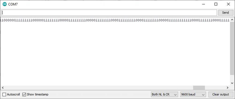
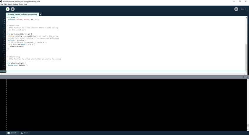
In the following images, I added a button to erase the drawing. The arduino sends the button state through the serial communication, as it appears on the Processing's console.


Sample.img
Sample.img

Here is the Arduino code :


color bgColor = color( 255 ); color penColor = color( 0, 0, 0 ); void setup() { size( 800, 600 ); background( bgColor ); noStroke(); fill( penColor ); } void draw() { ellipse( mouseX, mouseY, 20, 20 ); } void keyPressed() { background( bgColor ); }

Here is the Processing code :


void setup() { size( 800, 600 ); background( bgColor ); noStroke(); fill( penColor ); println(Serial.list()); // print list of all ports // change the number in [ ] to match // the correct port for your computer myPort = new Serial(this, Serial.list()[2], 9600); } void draw() { ellipse( mouseX, mouseY, 30, 30 ); } void serialEvent(Serial p) { String inString = p.readString(); println( inString ); if ( inString.equals("0") ) { Erase(); } } void Erase() { background( bgColor ); }

But it is not reliable as it doesn't react everytime the button is pushed. As the video shows, the drawing space is reset twice during the 1:30 minutes video while I am pushing the button all along.


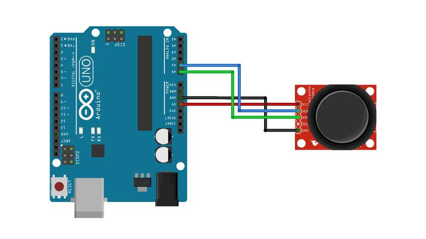
▸ Drawing using a Joystick and Arduino with Processing


In the following video, I am trying to draw using a Joystick to control the Processing sketch. Processing receives the values, corresponding to the commands, but it does nothing :(


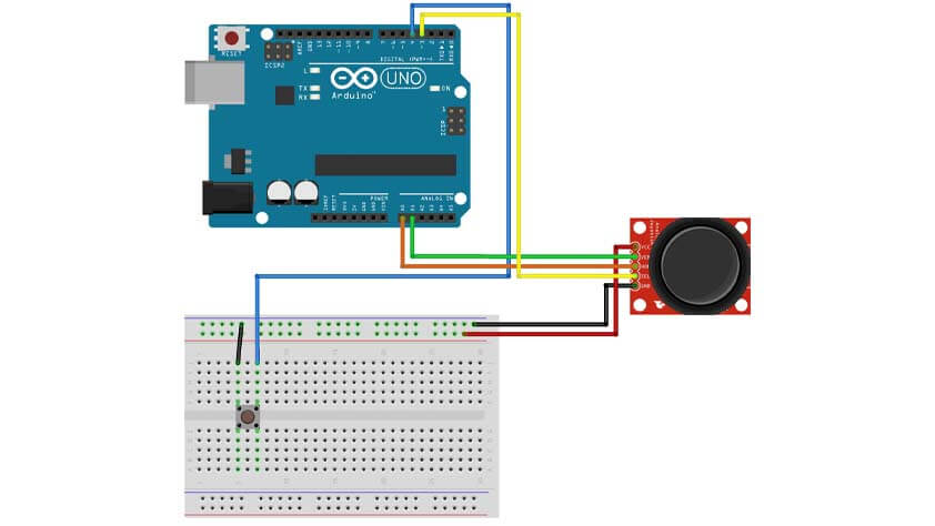
Here is the simple circuit to use the joystick :


Sample.img

I don't really understand the issue I had before, I think an "invisible" caracter is disturbing the identification of the command, what solved this was using if(val.contains("D")) instead of if(val.equals("D")), when Processing spot a D in the strings received, it applies the command.
I tried to drwa "hello", but to be honest, it is not very practical as there is a delay between the command sent from the joystick, to the command launched by processing.


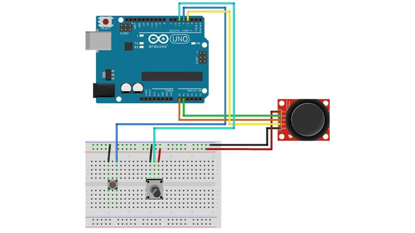
I added to the circuit the switch button in the joystick, when this button is pressed, the drawing is erased.


I modified the function of the switch button, now it is changing the color of the stroke randomly as it is pushed, and I added a switch button on the breadboard to erase the sketch.


Sample.img


I added a potentiometer to the circuit in order to modify the stroke width. In order to not overload the serial communication I mapped the potentiometer values from 0 to 1023 to 0 to 5, and it sends a character depending of the resistor position. Well. Communication is overloaded, the video below shows how slow it is. But it "works".


Sample.img


I took off the potentiometer and placed a switch button instead, when this button is pressed the stroke color changes to 255, the same as the background color, when I move and push on the joystick the stroke reappears as a random color is filling the stroke. It is not practical as we can't know where we are exactly, no pointer anymore, and if the background is modified, it becomes obsolete. It is a try.


Sample.img


▸ Arduino & Processing codes for the Joystick control


The sketch for Arduino :


int xPin = A0; int yPin = A1; int swPin = 3; int erasePin = 4; int potPin = A2; void setup() { Serial.begin( 9600 ); pinMode(xPin, INPUT); pinMode(yPin, INPUT); pinMode(swPin, INPUT); digitalWrite(swPin, HIGH); pinMode(erasePin, INPUT_PULLUP); digitalWrite(swPin, HIGH); } void loop() { // read in values int xAxis = analogRead( xPin ); int yAxis = analogRead( yPin ); int swState = digitalRead( swPin ); int erState = digitalRead( erasePin ); int potValue = analogRead(potPin); potValue = map(potValue, 0, 1023, 0, 5); if(xAxis >= 612) { Serial.println("A"); delay(10); } if(xAxis <= 412) { Serial.println("B"); delay(10); } if(yAxis >= 612) { Serial.println("C"); delay(10); } if(yAxis <= 412) { Serial.println("D"); delay(10); } if (swState == 0) { Serial.println("E"); delay(10); } if (erState == 0) { Serial.println("F"); delay(10); } if (potValue == 0) { Serial.println("G"); delay(10); } if (potValue == 1) { Serial.println("H"); delay(10); } if (potValue == 2) { Serial.println("I"); delay(10); } if (potValue == 3) { Serial.println("J"); delay(10); } if (potValue == 4) { Serial.println("K"); delay(10); } if (potValue == 5) { Serial.println("L"); delay(10); } }

The sketch for Processing :


import processing.serial.*; Serial myPort; String val = ""; int x = 0; int y = 0; void setup(){ String portName = Serial.list()[2]; myPort = new Serial(this, portName, 9600); size(500,500); background(255); noStroke(); x=width/2; y=height/2; fill(0,0,0); } void draw() { if ( myPort.available() > 0) { val = myPort.readStringUntil('\n'); } //println(val); //print it out in the console println("'" + val + "'"); println("x:" + x + " y:" + y); if(val != null) { if(val.contains("A")) { y = y+1 ; } else if(val.contains("B")) { y = y-1 ; } else if(val.contains("C")) { x = x-1 ; } else if(val.contains("D")) { x = x+1 ; } else if(val.contains("E")) { fill(random(255),random(255),random(255)); ; } else if(val.contains("F")) { background(255) ; } else if(val.contains("G")) { ellipse(x, y, 1, 1) ; } else if(val.contains("H")) { ellipse(x, y, 10, 10) ; } else if(val.contains("I")) { ellipse(x, y, 20, 20) ; } else if(val.contains("J")) { ellipse(x, y, 30, 30) ; } else if(val.contains("K")) { ellipse(x, y, 40, 40) ; } else if(val.contains("L")) { ellipse(x, y, 50, 50) ; } val = null; } ellipse(x, y, 5, 5); }

▸ Drawing by blowing


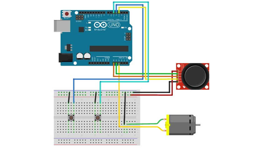
I added a RC DC motor as an input and modified the arduino sketch so the drawing commands are only available when data a received through the motor.


Sample.img


Here is the Arduino code


int xPin = A0; int yPin = A1; int swPin = 3; int erasePin = 4; int liftPin = 5; int blowSensor = A2; void setup() { Serial.begin( 9600 ); pinMode(xPin, INPUT); pinMode(yPin, INPUT); pinMode(swPin, INPUT); digitalWrite(swPin, HIGH); pinMode(erasePin, INPUT_PULLUP); pinMode(liftPin, INPUT_PULLUP); pinMode(blowSensor, INPUT); } void loop() { int erState = digitalRead( erasePin ); int liftState = digitalRead( liftPin ); if (erState == 0) { Serial.println("F"); delay(10); } if (liftState == 0) { Serial.println("G"); delay(10); } // read the input of blowSensor pin A1: int blowValue = analogRead(A2); delay(1); if(blowValue > 10){ // read in values int xAxis = analogRead( xPin ); int yAxis = analogRead( yPin ); int swState = digitalRead( swPin ); if(xAxis >= 612) { Serial.println("A"); delay(10); } if(xAxis <= 412) { Serial.println("B"); delay(10); } if(yAxis >= 612) { Serial.println("C"); delay(10); } if(yAxis <= 412) { Serial.println("D"); delay(10); } if (swState == 0) { Serial.println("E"); delay(10); } } }

Here is the Processing code


import processing.serial.*; Serial myPort; // Create object from Serial class String val = ""; // Data received from the serial port int x = 0; int y = 0; void setup(){ String portName = Serial.list()[2]; myPort = new Serial(this, portName, 9600); size(500,500); background(255); noStroke(); x=width/2; y=height/2; fill(0,0,0); } void draw() { if ( myPort.available() > 0) { val = myPort.readStringUntil('\n'); } //println(val); //print it out in the console println("'" + val + "'"); println("x:" + x + " y:" + y); if(val != null) { if(val.contains("A")) { y = y+1 ; } else if(val.contains("B")) { y = y-1 ; } else if(val.contains("C")) { x = x-1 ; } else if(val.contains("D")) { x = x+1 ; } else if(val.contains("E")) { fill(random(255),random(255),random(255)); ; } else if(val.contains("F")) { background(255) ; } else if(val.contains("G")) { fill(255,255,255); ; } val = null; } ellipse(x, y, 5, 5); }

▸ Creating an application from Processing


I found these helpful ressources to guide me through these steps :


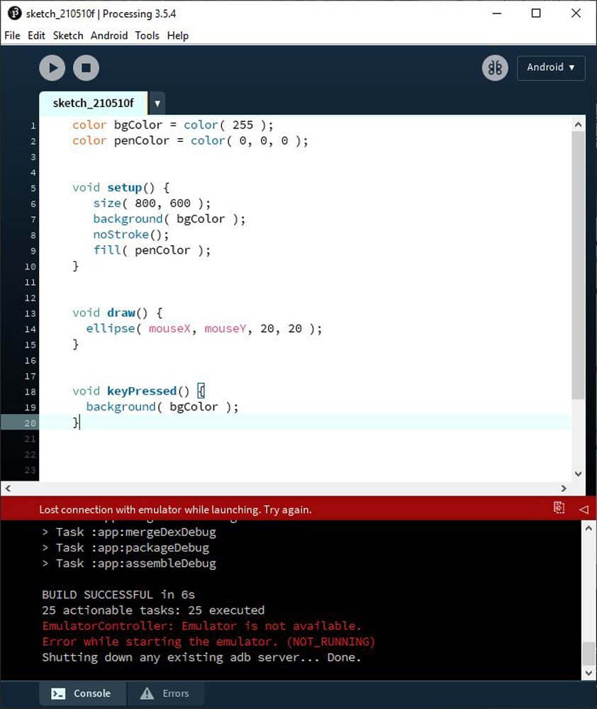
I downloaded the softwares required, and from Processing I downloaded the Android mode.


Sample.img
Sample.img

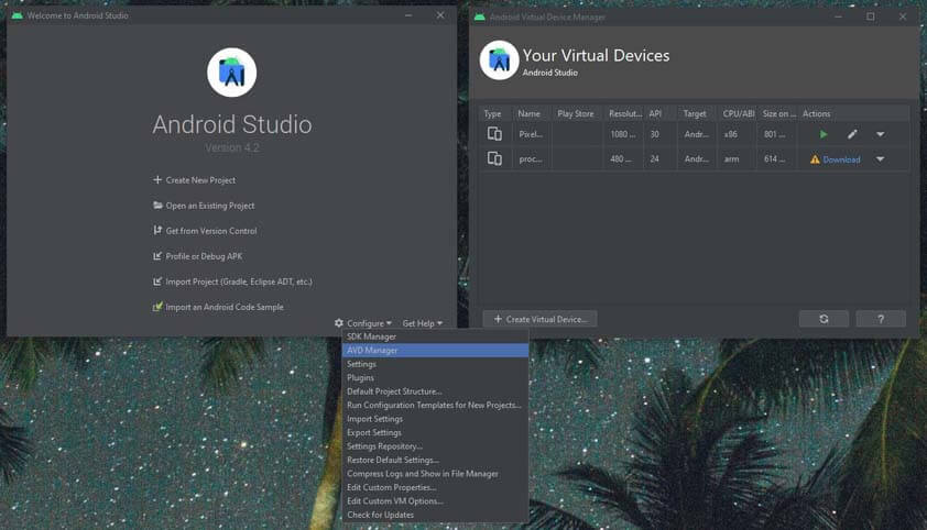
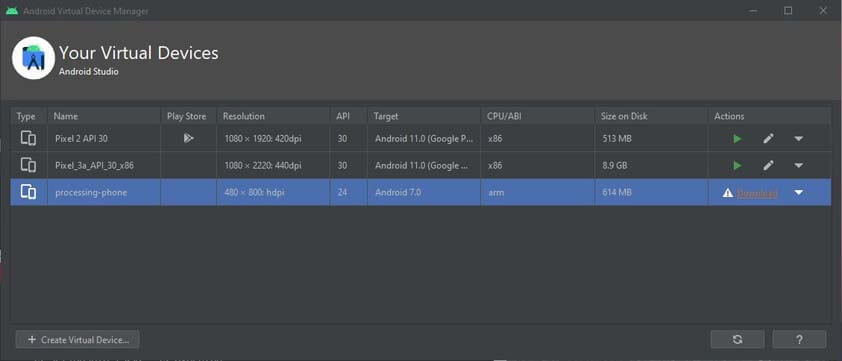
I Lauched the Android Virtual Device (AVD), but from here I was unable to download the system image package to run the "processing-phone". I didn't find useful tips so far. Here is the error message :


Sample.img

▸ Creating an application using the APDE - Android Processing IDE


The APDE app was a great discovery of the week ! It is basically the android mode of processing, so the simulation is easier to "emulate", the ADPE Sketch Preview plug in allows to open the result in a console. The App mode allows to generate an .APK file, that, from my understandment, is deleted right after trying it. But this part isn't true on my phone so far.


Sample.img

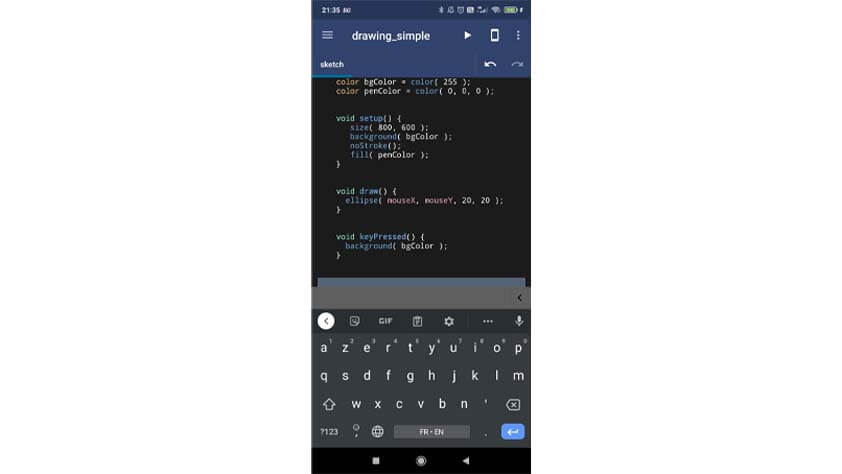
The following video is a screen record from my phone, I am using the APDE App to simulate the sketch first, then as an APK file installed on my phone.


To go further I have to find how to establish the communication from processing to my phone using a HC-05 module. > SPP port on android


▸ Testing the application with the board I made


I finally made my board and I will now try to use th Blow controller I made to control this appplication.

‹ Previous : Networking & Communications   •   Next : Wildcard Week ›