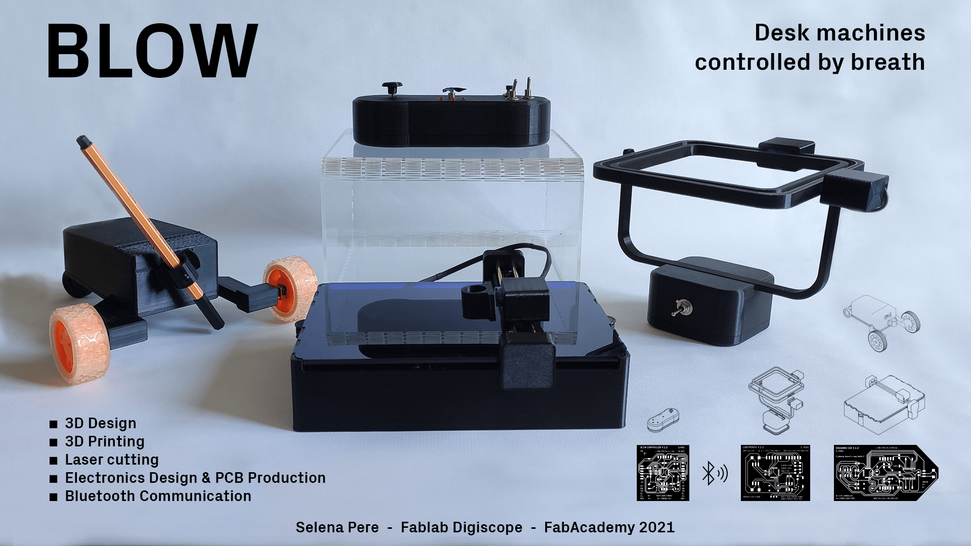
☛ BLOW
Here is the presentation video for Blow. The video has a fast pace, be prepared, and dorry about that. I will make a longer version of it.
☛ Content :
Final Project Intention
Making the Blow Controller
2D Design
Breadboard Prototyping
PCB Making
Prototyping & Integration
Making the Drawing Car
2D Design
Prototyping attempts
Breadboard Prototyping
PCB Making
Prototyping & Integration
Making the Labyrinth
PCB Making
Prototyping & Integration
Making the Drawing Machine
2D Design
PCB Making
Prototyping & Integration
Wireless Communication
☛ Final Project Intention
As a final project for the Fab Academy I would like to develop a personal research on a composite material made with sawdust that I began in November 2020, and to improve a project that I made as part of my graphic design diploma.
▸ Tools for exercising breath control
Two years ago I made prototypes of tools that could be useful for exercising breath in a speech therapy context. I made it as my graduation project with the help of a speech therapist who gave me feedback during the research, and a computer sciences students who made all the electronic part of the project. I would like to improve this project in order to make it more functional, and to document it properly so it can be shared. The original project can be fin on my website
It works in a simple way, the controller is made with propellers on which the user has to blow in order to use the machines. But the current prototypes are prototypes with a lot of issues that need to be resolved :
- The Blow Controller
- Add a potentiometer or something similar in order to calibrate the blow that needs to be produced by the user.
- Use only one propeller, and not four. It make the user turn his head to blow on a different propeller, involving searching for the propeller by looking at it, and therefore it is harder to focus on the drawing activity. One propeller should be used with directional buttons. How to place the buttons that are well placed for the user ?
- Make the "box" of the controller with composite material, using molds or other processes.
- Data recording for visualization & analytics of the training ?
- The Sketcher
- Use belts instead of wire and rubber to move the axis. I am fond of low tech systems but I would like to upgrade this part to gain precision in the drawings produced.
- Add a system to lift up the pen from the paper so it is not constantly drawing. I'd like it to be a discreet system.
- This is an option that could be interesting : Add a "retro lighting" under the drawing surface, it could display patterns that the user could reproduce.
- Make circuit and PCB.
- Make the "box" of the controller with composite material, using molds or other processes.
- The Drawing Car
- Center the pen in the middle of the wheels axis, so the car can draw ninety degrees angles.
- Add a system to lift up the pen so it is not constantly touching the surface it is drawing on.
- Make circuit and PCB.
- Make it with composite material.
- The modularity
- All of the machines are working with two motors, so I think that modularity between the machines might be an interesting aspect.
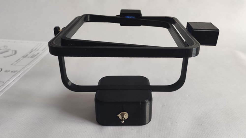
This is the machine controlling the others, it "captures" the blow and translates it as a signal to a microcontroller.
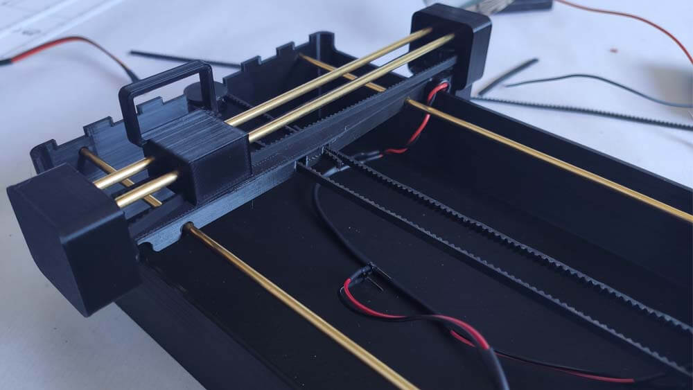
This is a two axis drawing machine, but the prototype is lacking of accuracy and precision, because of the materials I used.
This is a little car which carry tools to draw. The current protoype is lacking of ergonomy and precision.
▸ Composite material from sawdust and casein glue
I made tests mixing sawdust and casein glue, putting the mixture into 3D printed molds, then making it dry. And it produced samples that seems to be strong enough to make things out of it. I would like to make more tests in order to evaluate the properties of this material, and I would like to make functional objects using it.
☛ Making the Blow Controller
2D Design
Breadboard Prototyping
PCB Making
Prototyping & Integration
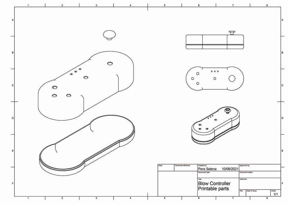
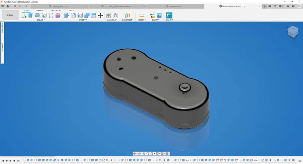
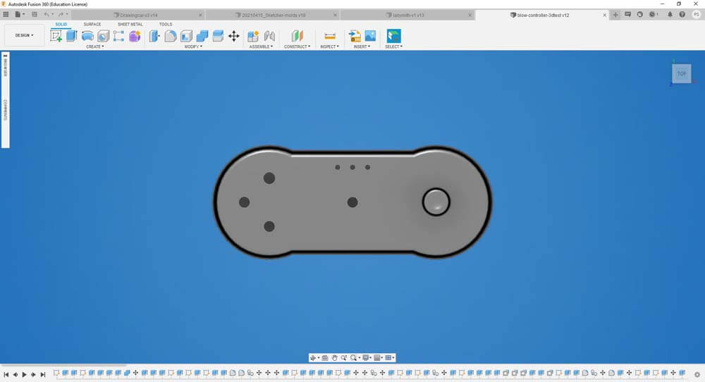
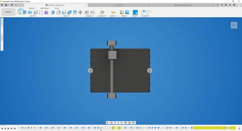
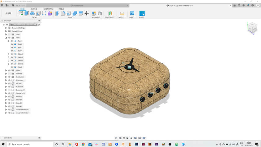
▸ 2D Design
During the second Week I tried to model the controller first, here is a video capturing the history of steps in Fusion 360.
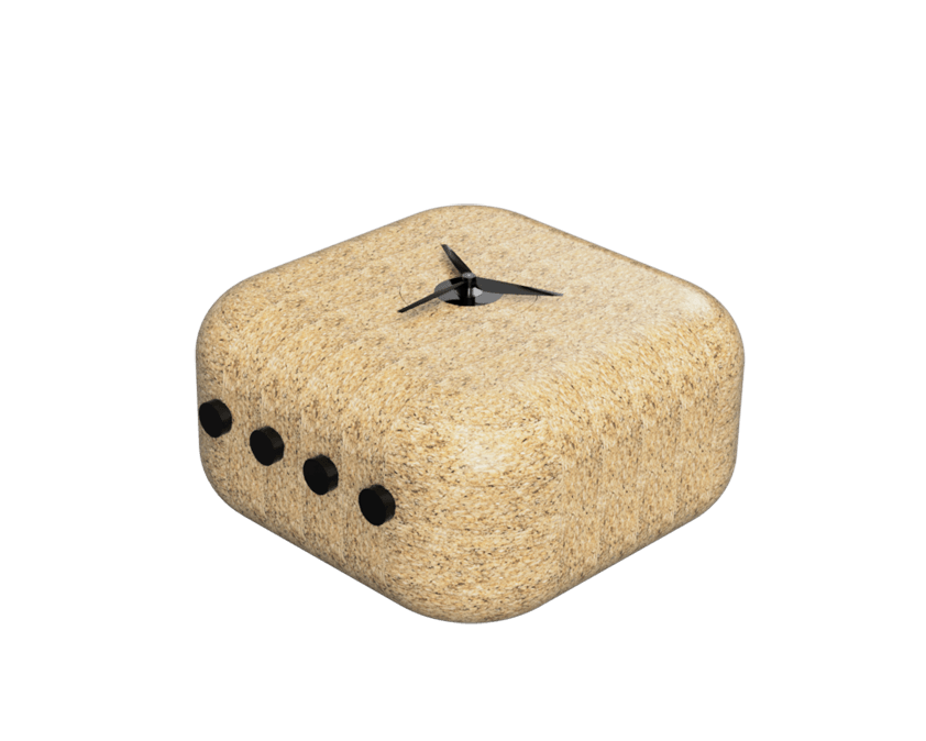
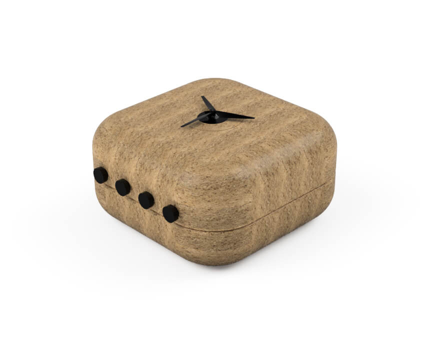
Here are two render with the composites samples I added in my library, the size of the sawdust is different and I forgot to turn off the glossy appearance of the material on the first render.
Assembly joints
During this discovery of Fusion 360, I also applied assembly joints to my objects where it belongs, in order to create animation thank to the "Animate" workspace in the software. The propeller can turn, and the buttons a moving in the right axis with limitations added to get the right movement. I found limitations to this when trying to "articulate" the Sketcher 2 as I couldn't apply slide joints to miroring objects/or I couldn't change the side or rotation.
▸ Breadboard Prototyping
During th Input Devices week, I made a first prototype for the blow controller. The Rc motor in an input device measuring blow strenght, in this case. A bargraph, three LEDs in a row are displaying the blow intensity that is measured.
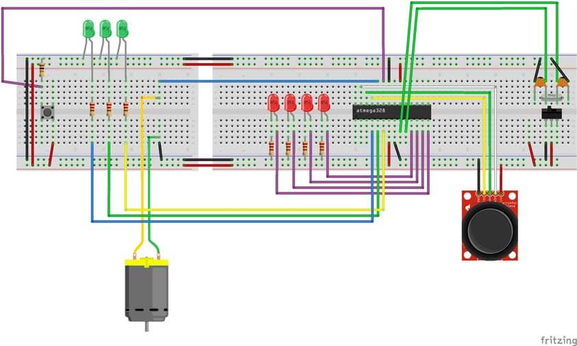
Here is the circuit of the Blow Controller with a joystick on a breadboard.
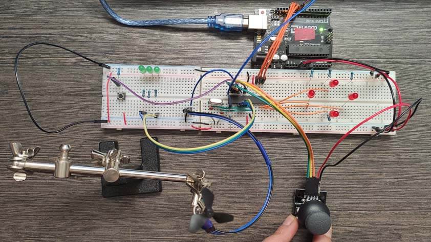
And here it is working :
▸ Arduino code fot he Blow Controller (Zipped)
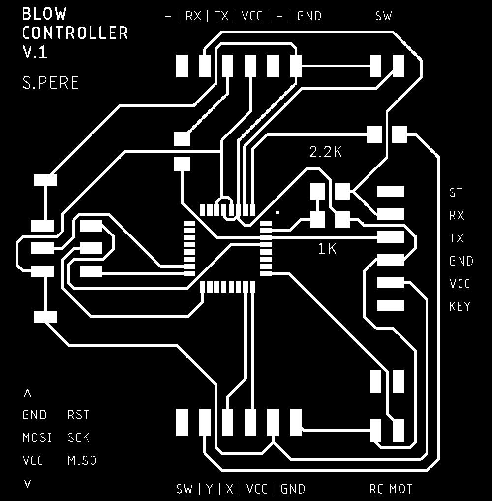
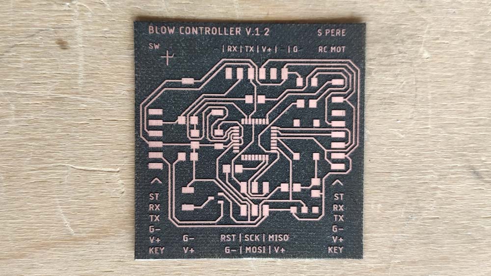
▸ PCB Making
▸ First attempt
I used the circuits I made on breadboards during week 10 to translate these big circuits in a condensed one. I designed the PCB using Eagle, the process I used is described in Electronics production.
This first attempt has several issues : the text didn't came out well as the size is too tiny for the letters to survive this process, I will modify the text size to 0.5 instead of 0.4.
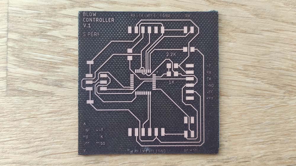
Antoher issue I met was soldering itself. My soldering iron has big tips, and therefore it was complicated to soder the microcontroller. In this attempt I only soldered the pins that are being used in the circuit.
A bigger issue this board has is missing components, after showing it to my insructor, I forgot the reset resistor that is required. Also, a capacitor for the microcontroller and a polarity protection would be better to add.
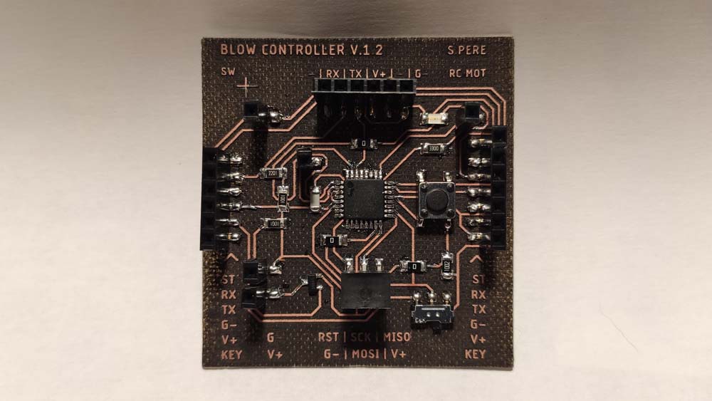
▸ Lasercutting & Soldering
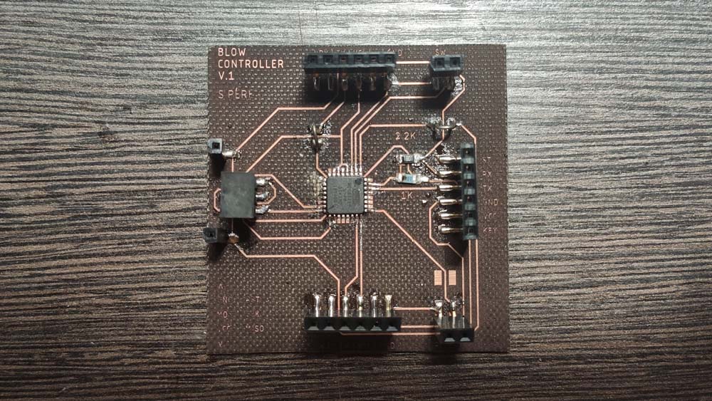
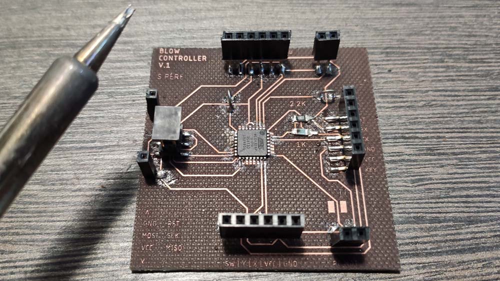
Using the advices Jonah provided me, I modified the board and added the components that were missing.
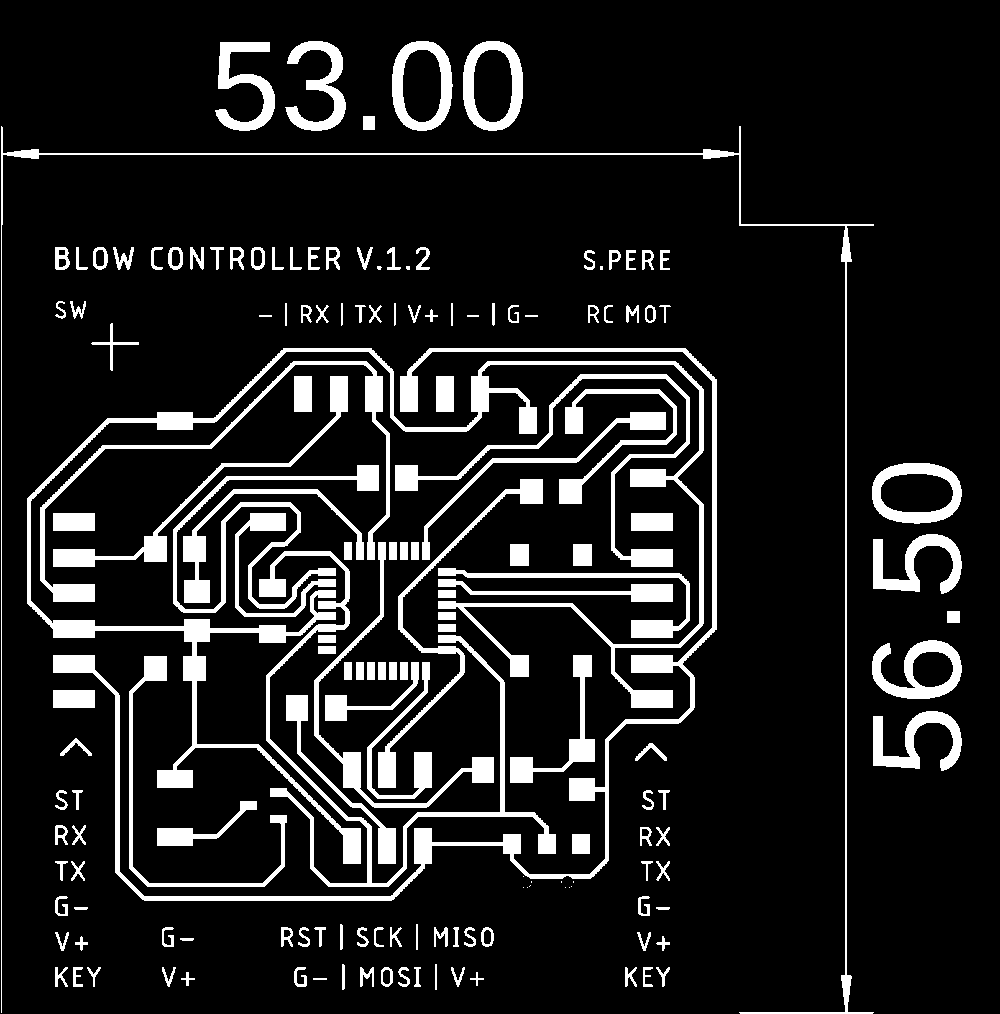
Here is the final circuit schematics for the Blow Controller, the image can be enlarged in another window.

This time, using a heavier size for the font, the text came out very well.
The soldering part was also easier by using a soldering iron from the fablab, their tips are thiner, the microcontroller was a little bit easier to solder.
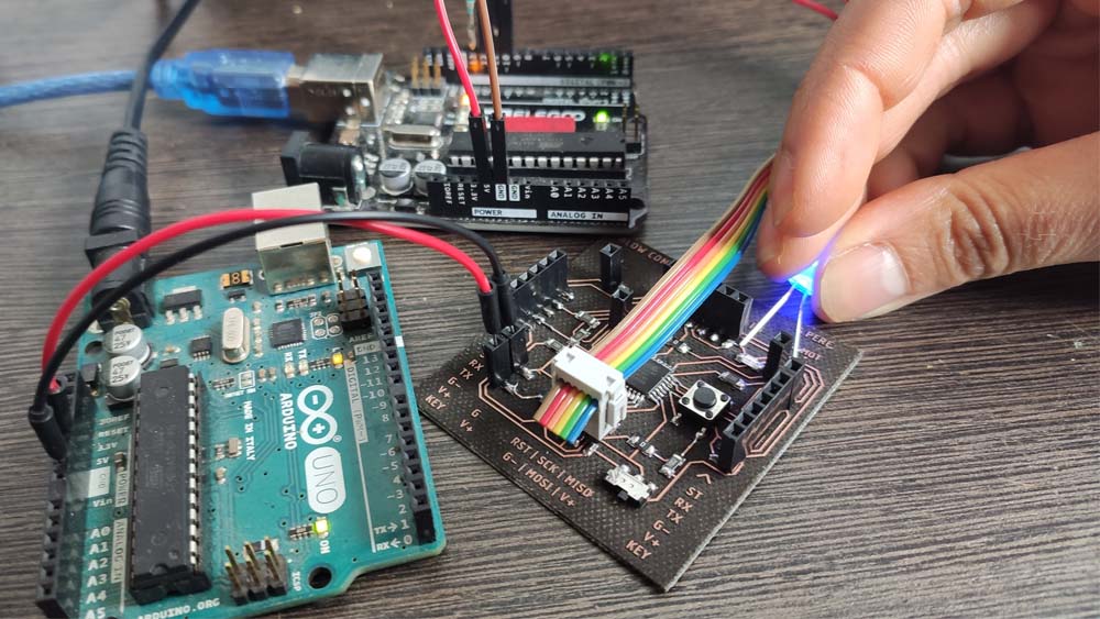
▸ Programming and testing
I used the Arduino IDE to program the board using an Arduino as an ISP and another Arduino to power the Blow Controller board. I uploaded the Blynk example in it and it works, but the LED isn't working. I will have to desoldered it to solder another one.
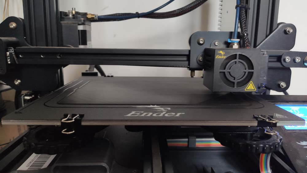
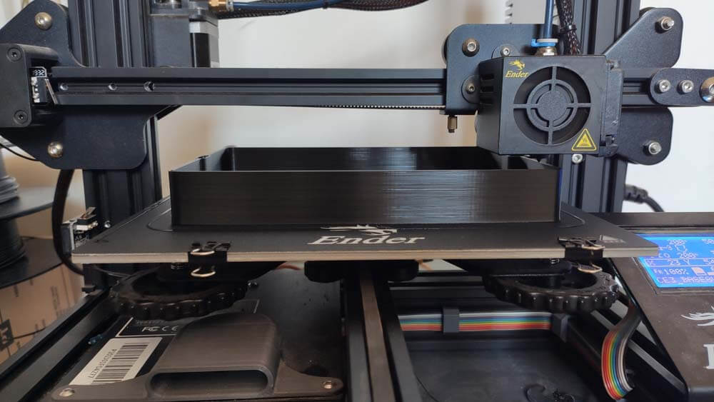
I designed this box in which I will integrate the board. It is alo a useful print to test the ergomy and proportions of the controller.
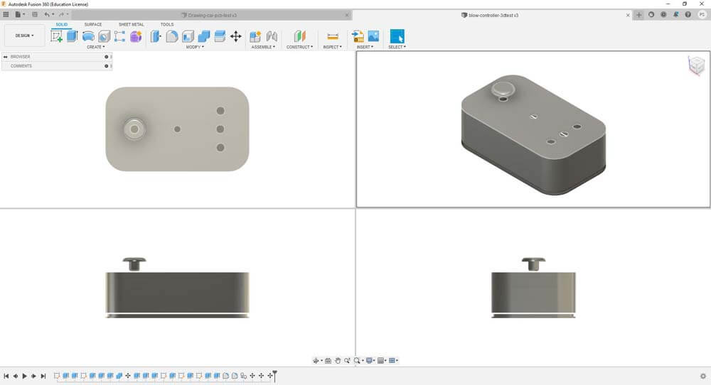
After a few hours printing :
I still need to make some soldering and tidying in the wiring. Also, it needs a few modifications to add the bargraph and another switch.
▸ Files of the week (zipped)
▸ Prototyping & Integration
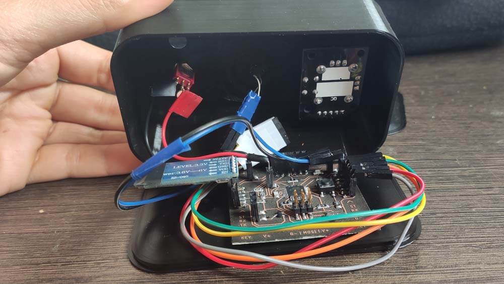
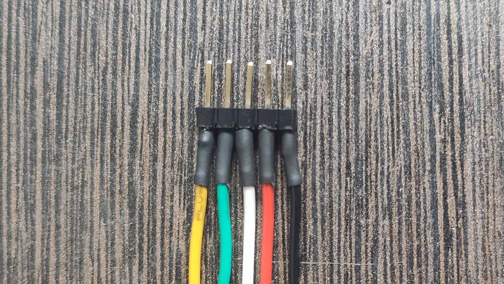
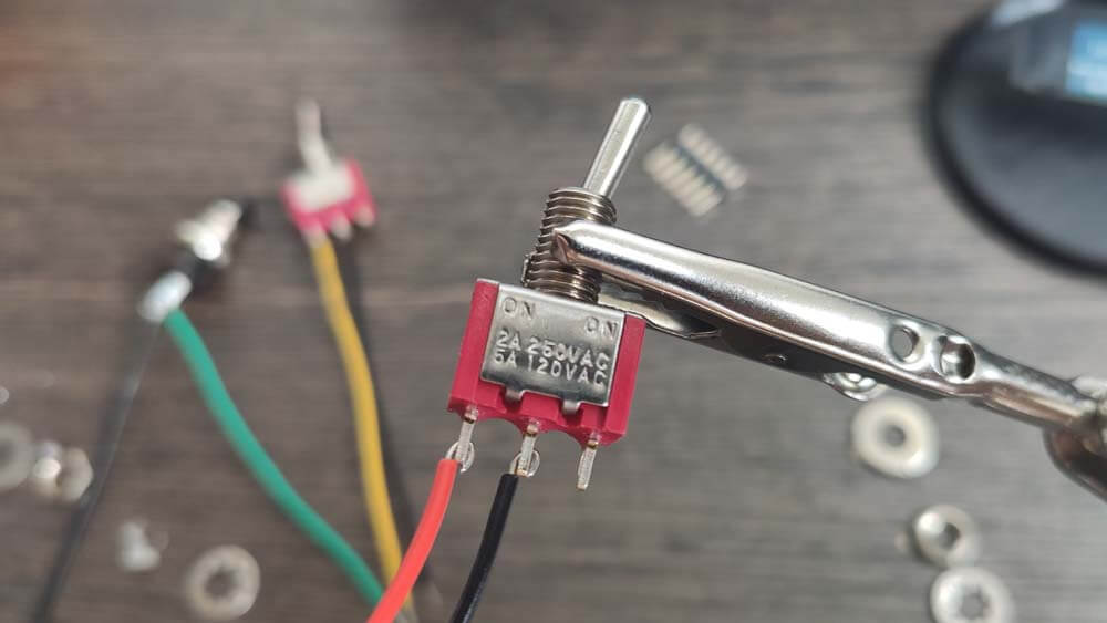
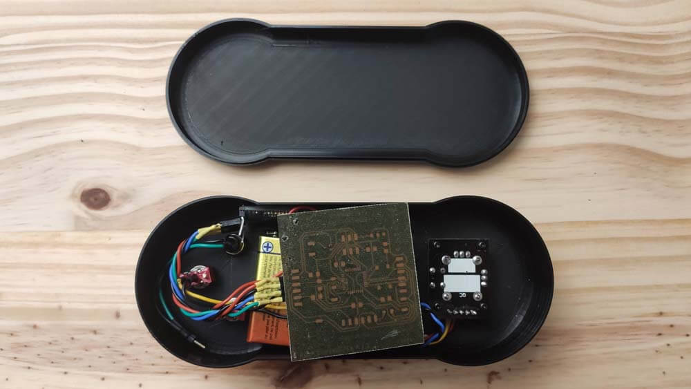
As explained above, I need to work the wires integration in order to make it fit the controller body I designed. I soldered every parts, headers, switches and LEDs, and protected these using heat-shrinkable sleeves, so no shorts, and maybe it gives a little mbit more resistance to the soldering. Maybe.
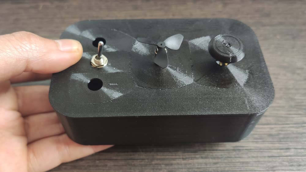
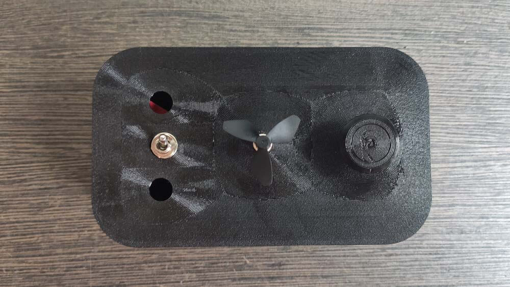
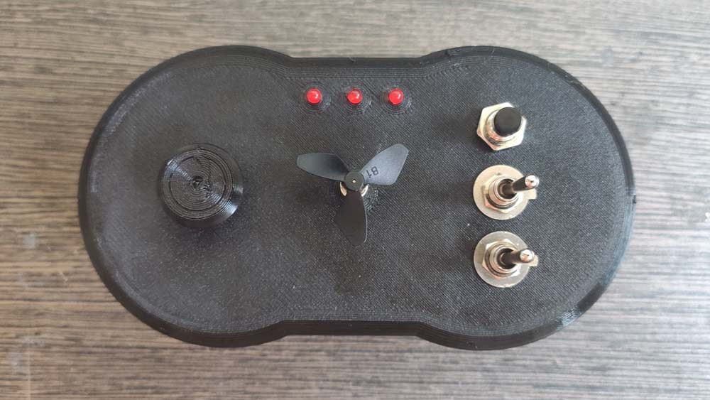
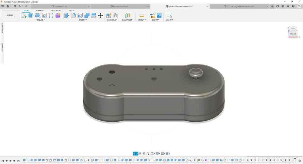
I reworked the controller's shape, adding two circles so the controller is easier to "grip" with both hands.
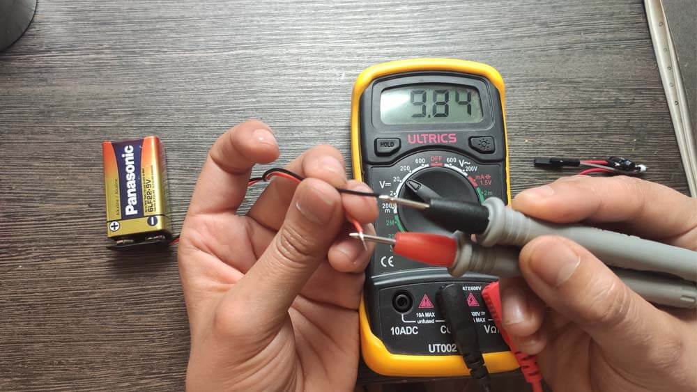
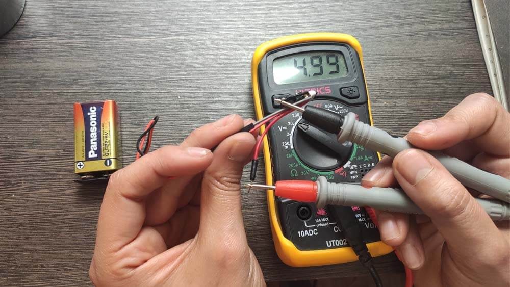
It turned out that I forgot some kind of important "detail". Where do I fit a battery in this ? I need to power the circuit with 5V, I have been doing that using an alimentation so far. I added a Voltage regulator to my circuit, so I can add a 9V battery in the controller's body. But now, even if the wires are better integrated, they are "hard" and they are taking space. I will redesign the controller so the circuits and components can fit better in it.
In the next images I am measuring the voltage of the battery alone, and then the battery with the Voltage regulator module. It drops from 9V to a little bit under 5V. It is great, and I will have to add this component on the board to gain space.
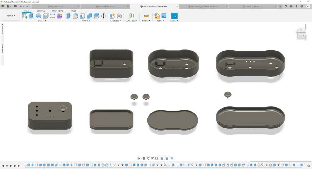
I modified the Controller's body again, so my Frankeinsteined board can fit in it properly. I did not wanted to make it higher, so I made it wider.
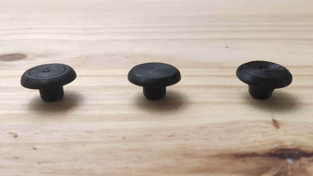
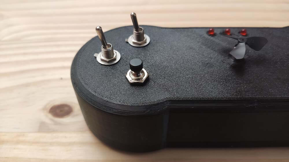
I tried several times to print the thumb joystick cap, it was not that easy because the base is a smal surface and it did not adhere properly on the printer's bed. I used the "Tree" support, in Cura's Slicer, and the result was more satisfying this way.
And I printed and assembled the Controller again :
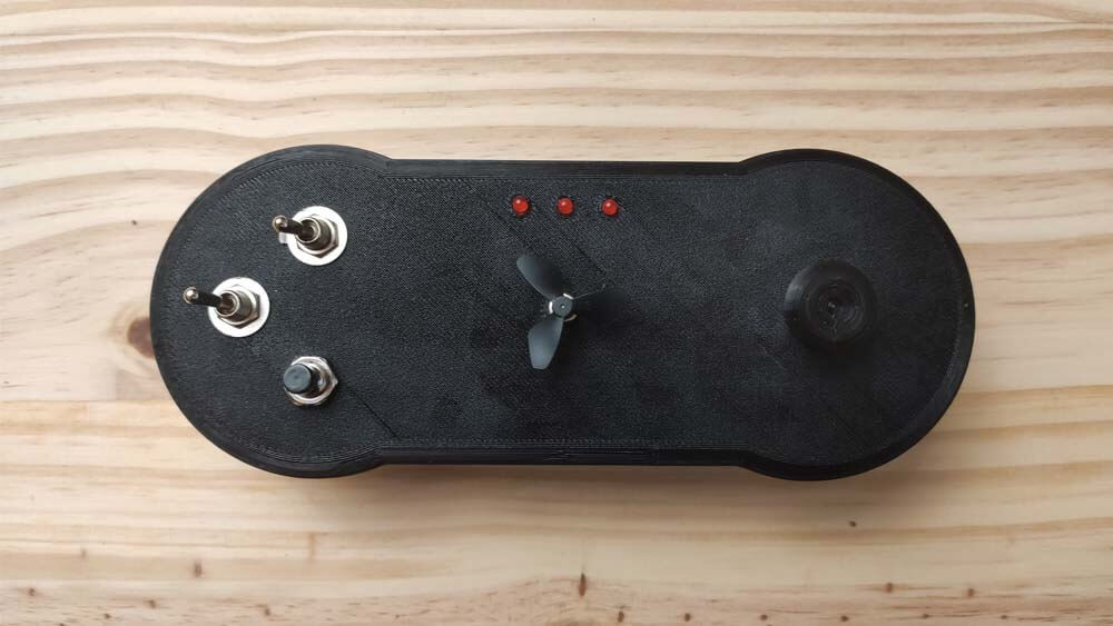
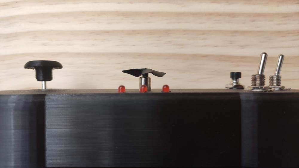
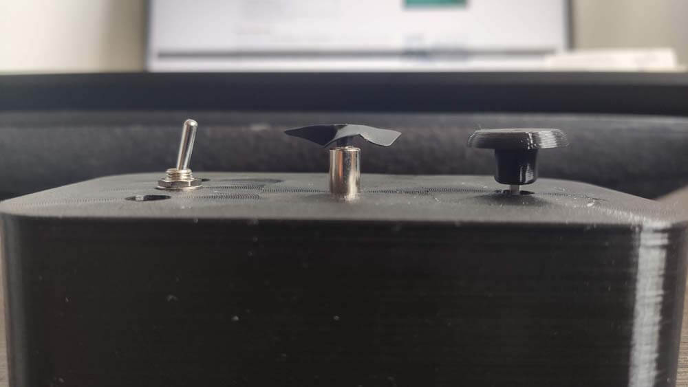
The integration is better, the joystick module is screwed and fits nicely, I re-arranged the switches so there is more space between them so they are more accessible.
☛ Making the Drawing Car
2D Design
Prototyping attempts
Breadboard Prototyping
PCB Making
Prototyping & Integration
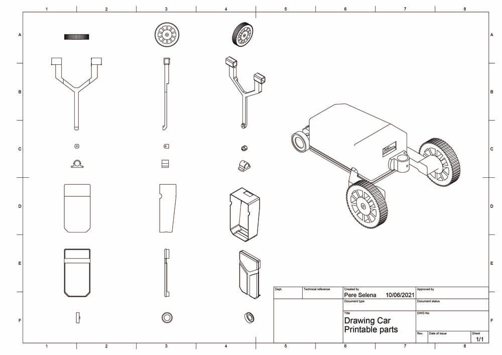
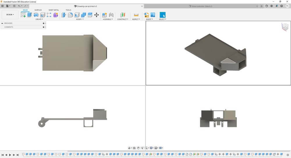
▸ 2D Design
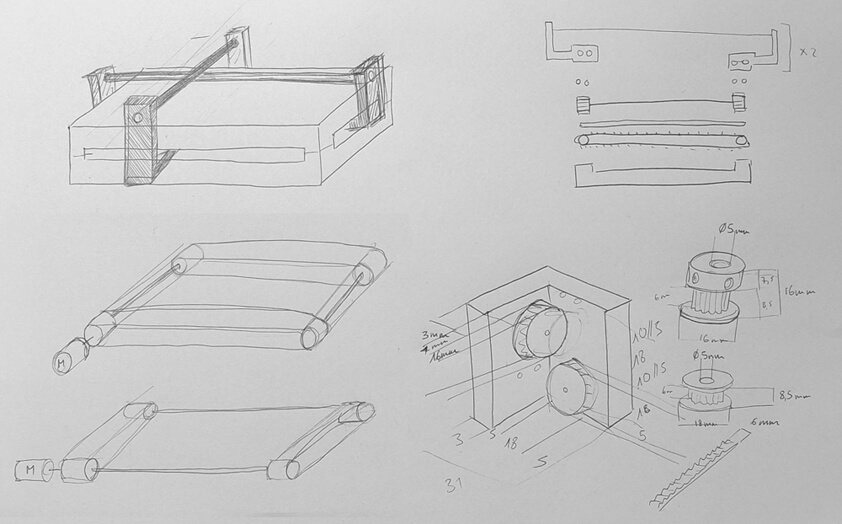
What I want to improve from my previous drawing car is the pen holder. I would like to add a servo motor to carry the pen holder, so that the pen is not constantly touching the ground. Here is a sketch of this system.
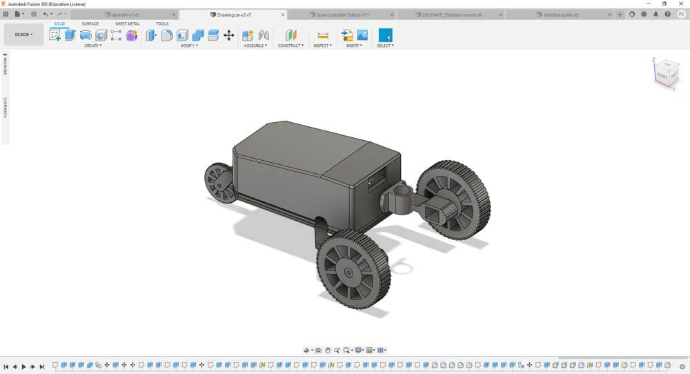
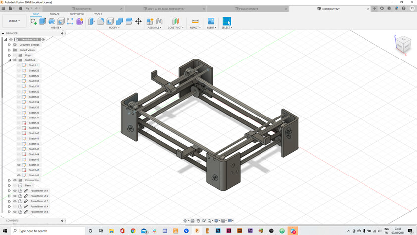
I design a frame on which this system could be placed, trying to optimize space. The motors are not modelize from real ones, so this model is not totally accurate regarding measures.
I tried more rendering options with environment, several lightning parameters, and depth of view.

▸ Prototyping attempts
Week 05 : Tests for 3D printed tyres
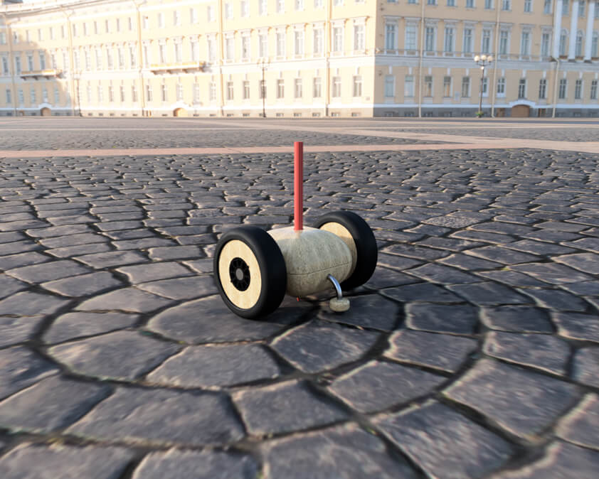
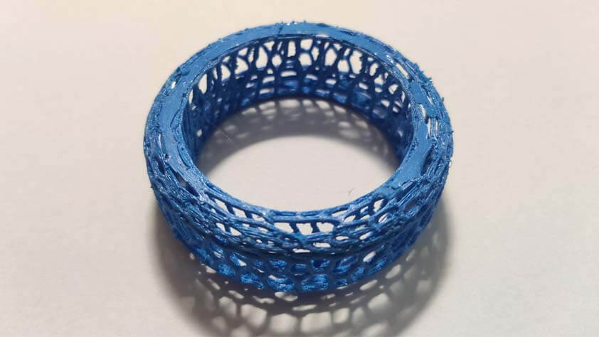
For this part I tried to make sort of airless tires for the "Drawing Car" I designed during Week 2. I exported a STL file from my previous work and imported it in MeshMixer Autodesk.
Here are the steps I went through :
- Select the model and display meshes, then
- Click Edit > Reduce 50%, and repeat this step : it works better if there is less triangles
- Clear the Selection
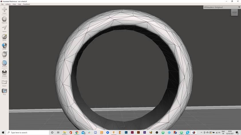
- In the left panel, select Edit > Create Pattern
- In the window appearing select Dual Edges pattern and modify the parameters until it fits, and click Accept
- You can then export the file
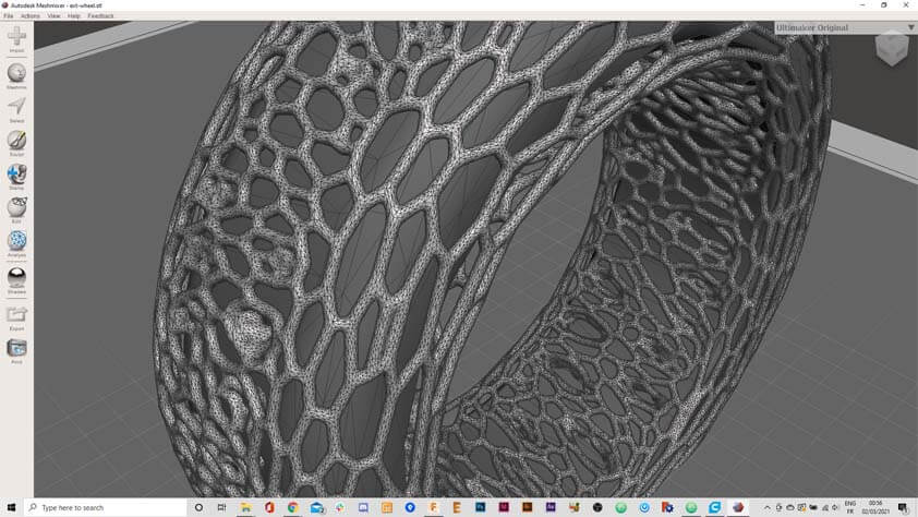
Here is the 3D printing attempt with the Ender 3. I reduce the size of the tire from 80mm of diameter to 50, so it would take less time to print. Thinking twice, this was not a good idea as the meshes were already 1mm of width. The result shows a lot of stringing on the printed model, it probably means that the retractation of the filament is too slow in that attempt.
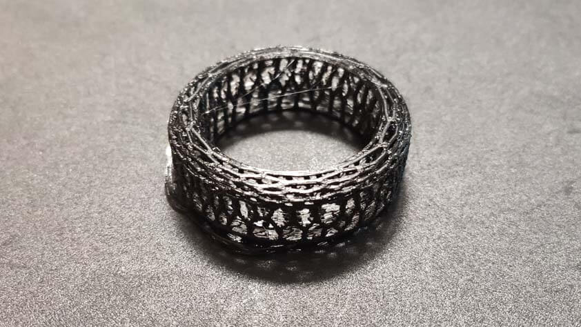
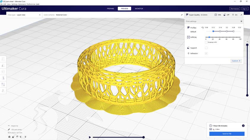
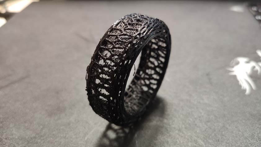
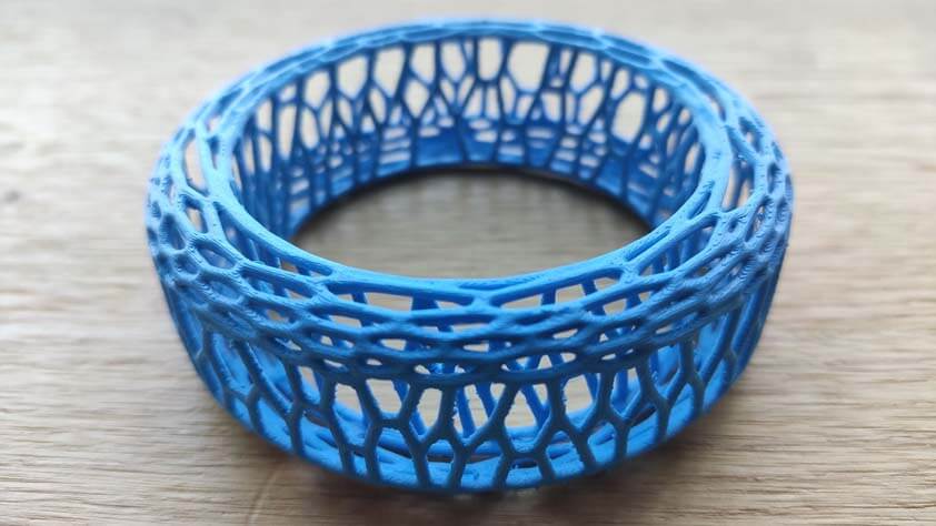
I made another try with the Ultimaker 3 Extended, using a nozzle of 0.25mm. I kept the reduced size of the model for this test as well, there is less of the stringing effect, but there is still. I had to use an adhesion support, between the model and the build plate only, because it would not adhere to it without. This is not ideal as it is hard to pull it off of the model without damaging it.
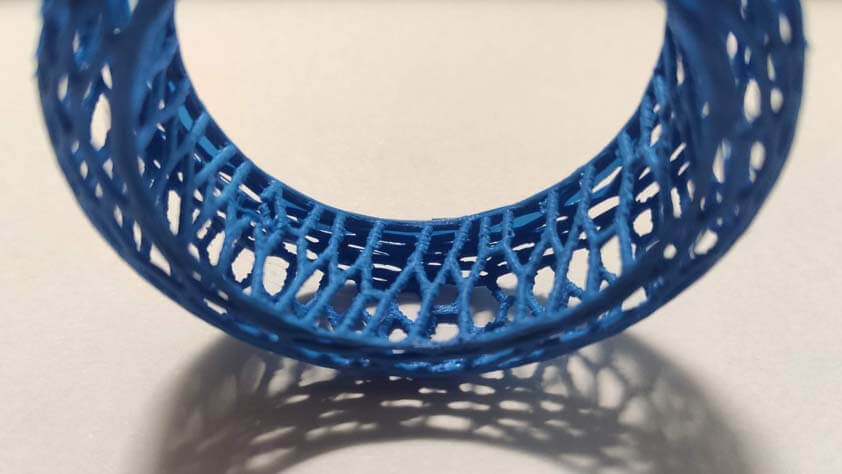
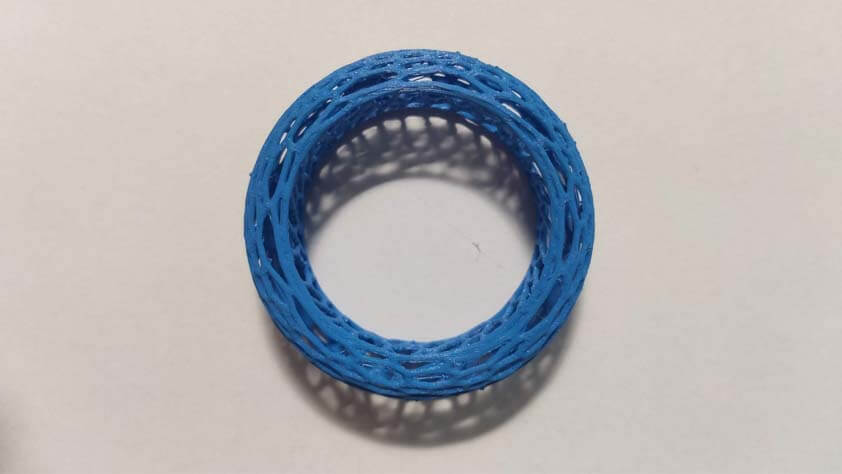
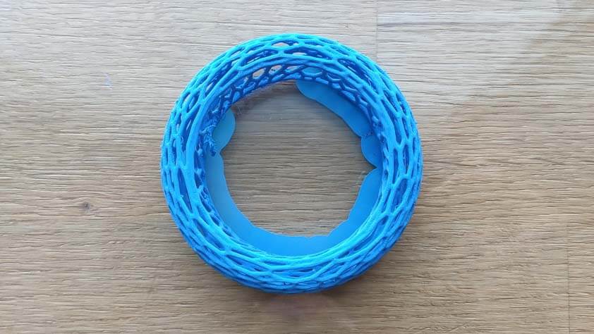
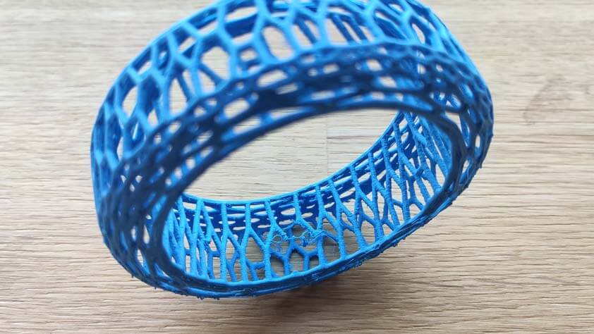
Here is another attempt, still using the Ultimaker 3 Extended, with 0.1mm of layer height, 20mm/s of travelling speed, 28mm/s of retractation speed, and "Enable retractation at layer speed" ticked, in Cura slicer. Stringing is less present but the brim is still hard to get rid of, and the bottom layers (the first layers printed) are not very smooth. At this point I could try to lower the heat of the print core, or just redraw this model so the angle is easier to produce with this machine.
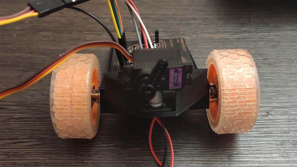
Prototyping the Drawing Car body
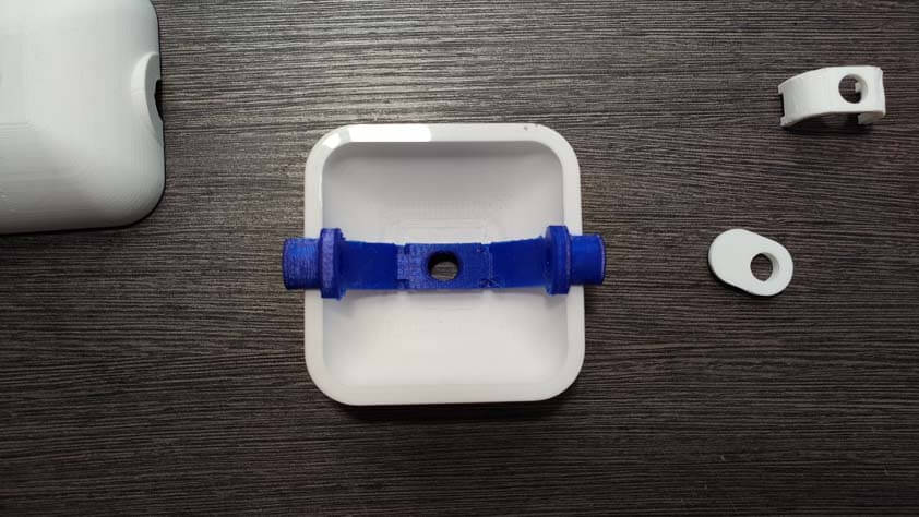
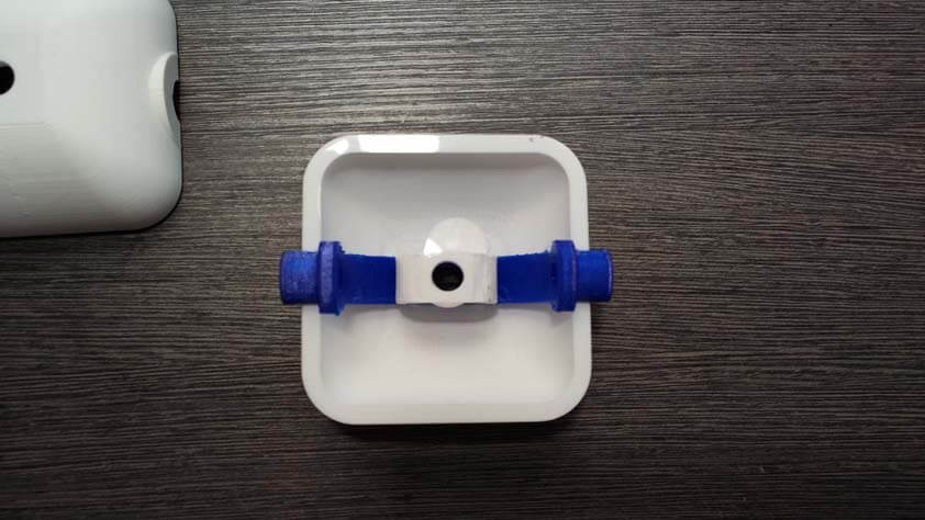
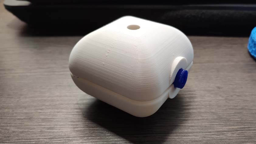
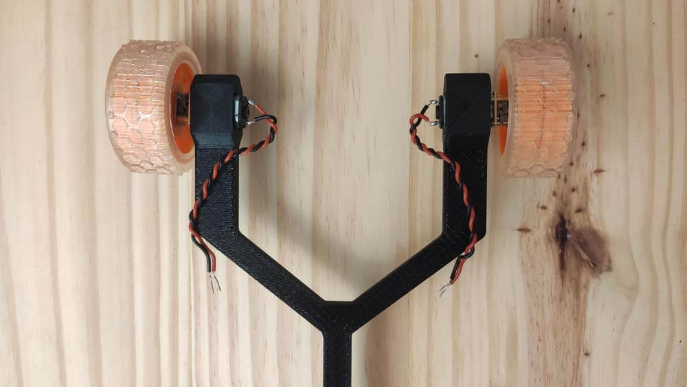
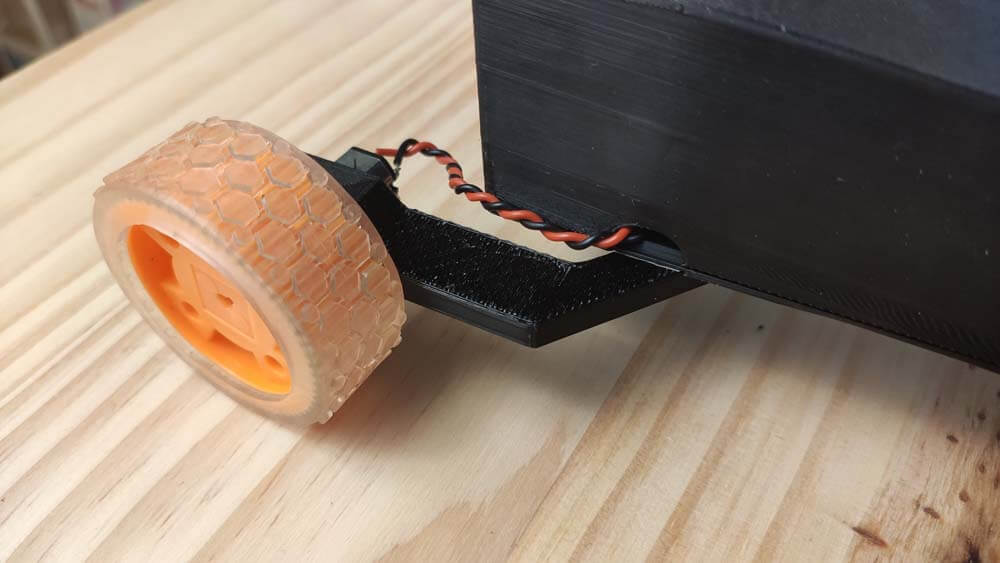
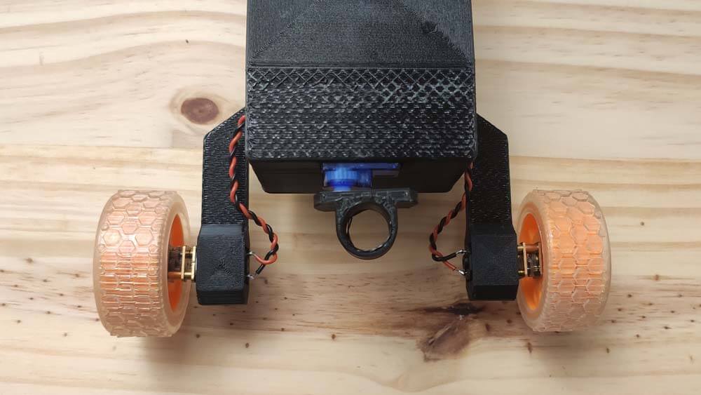
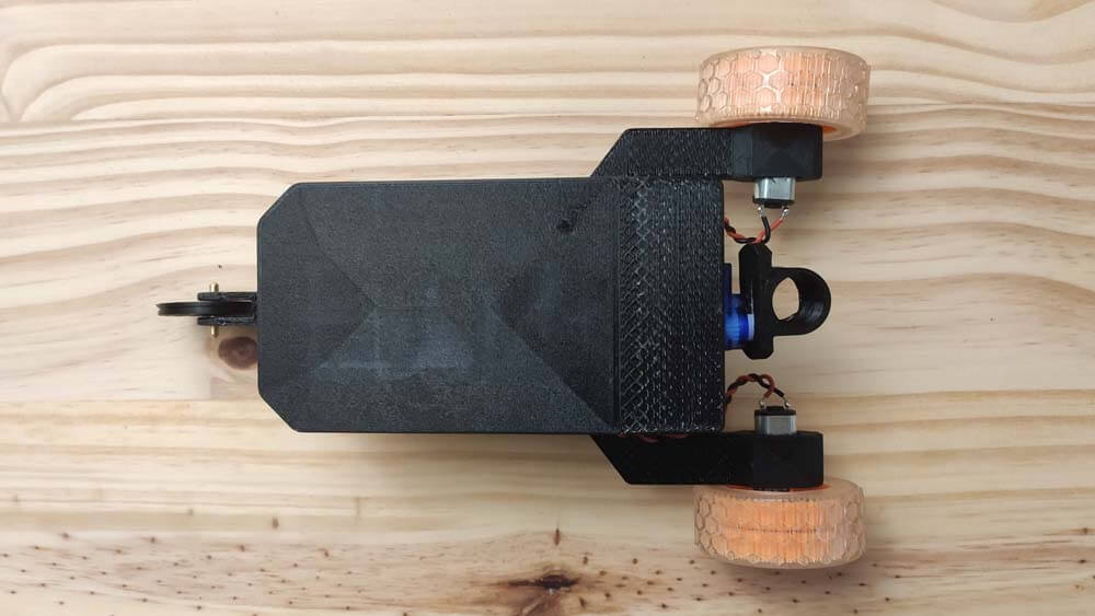
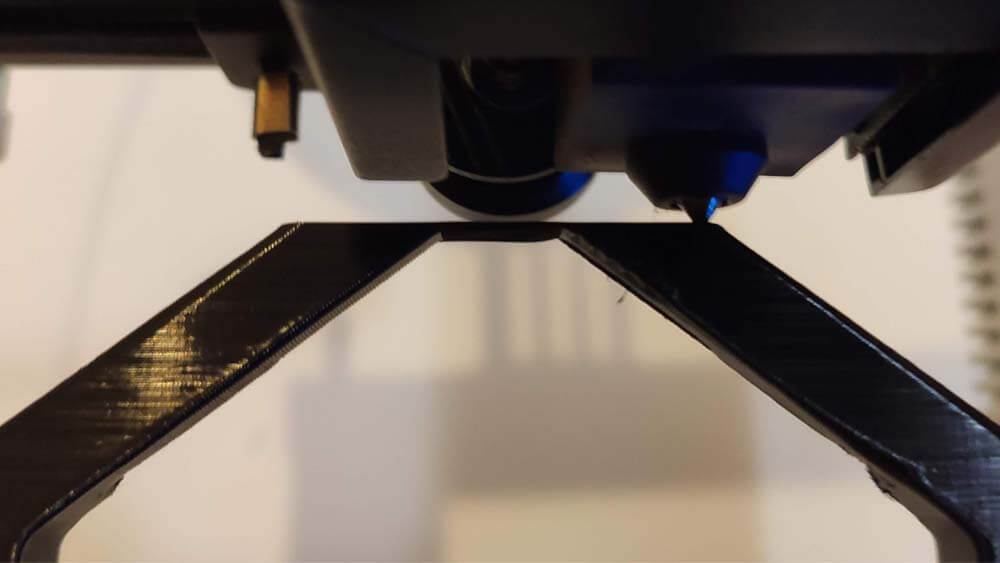
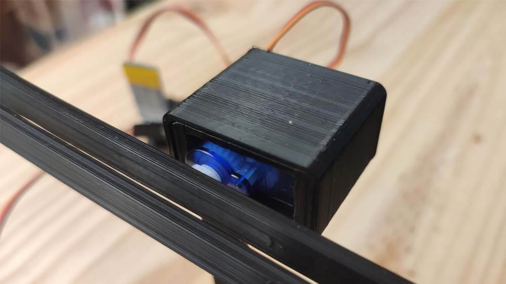
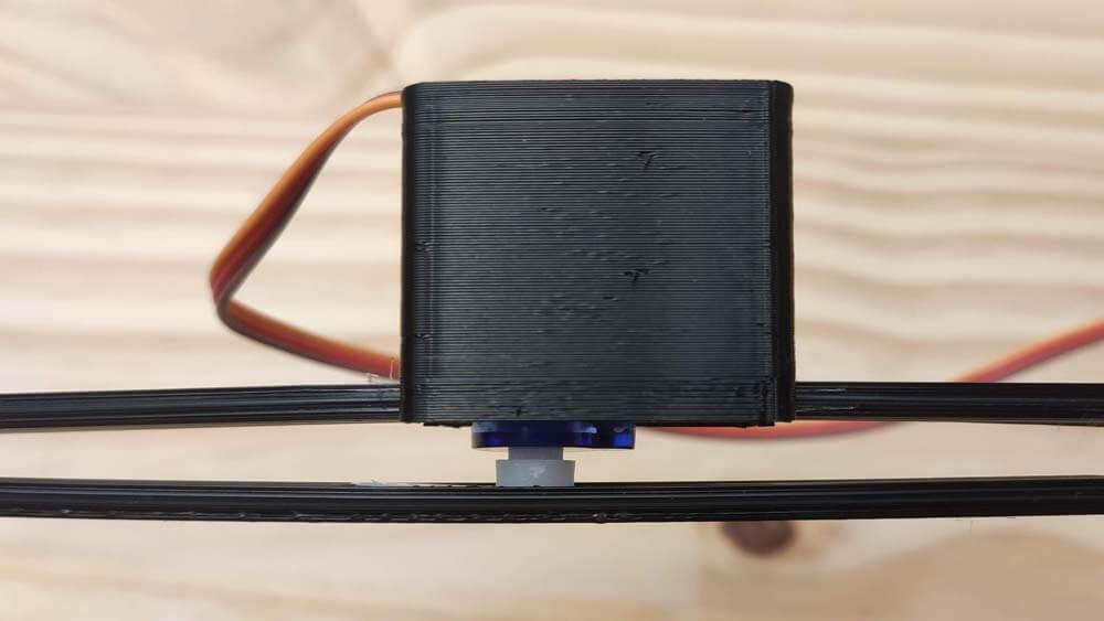
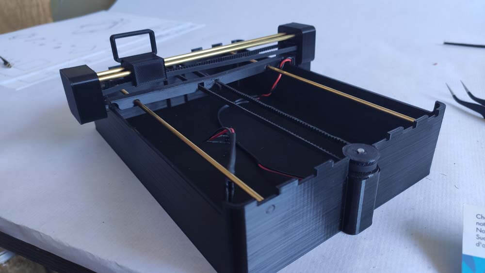
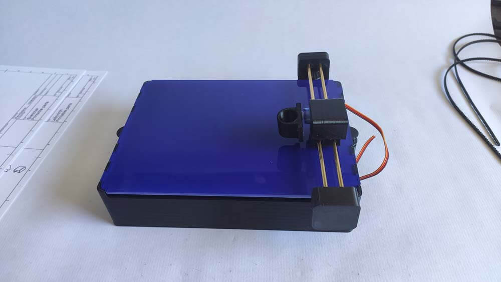
Here is a test for prototyping the drawing car, I used PLA filament for the body and the pen-lift mechanism (the white "box"), and TPU for the frame (the blue part).
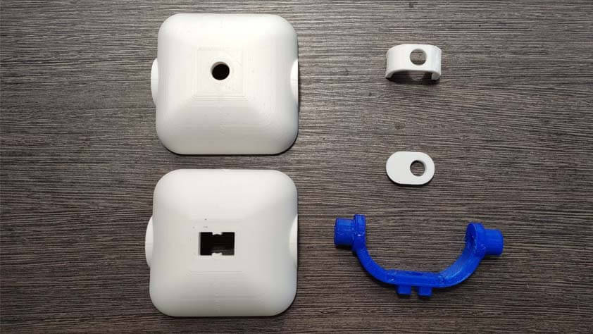
The parts are assembled by a "press-fit" logic, the tpu filament is useful as it is flexible, the clearance is low, so it fits pretty well in the PLA.
Next step will be to implement two gear motors and a servo to lift the pen. > Output device week
☛ Molds for compressing sawdust composite
I would like to make most of my final project parts from composites materials (a mix of sawdust and casein glue that I documented here during the Pre-Fab Academy).
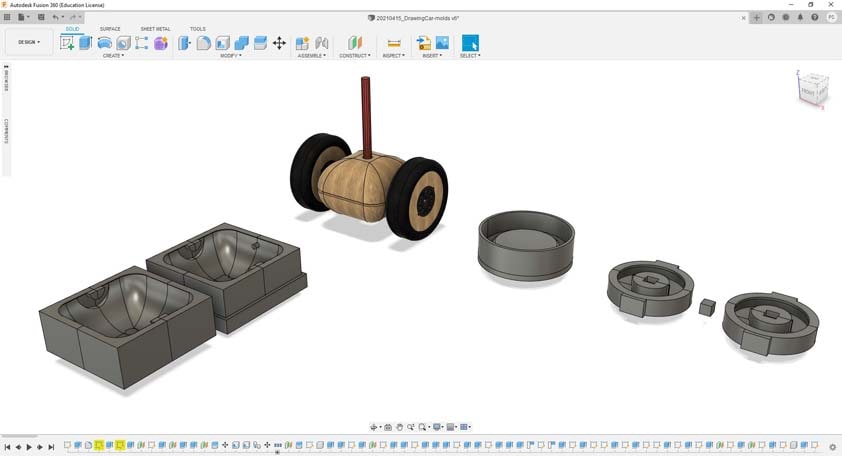
Here is my first test for the body of the drawing car in the sreenshot above.
The process then is to prepare the casein glue, which is made of milk, vinegar and baking soda, to prepare the sawdust, from walnut wood in this case, I make it pass through a colander to use the thinner part of it, and mix both to obtain a desnse clay.
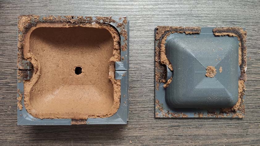
The clay is placed into the molds, in the edges first, and in all the mold, then it is pressed.
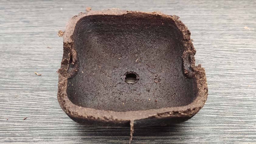
After 24h of drying in the mold, it has to be open in order to prevent the mix from rotting in it. Then the next step is to wait for it to dry before demolding it completely.
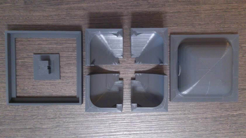
Here is the first demolding test. My error was to be impatient, and to take out the squared ring maintaining the mold when opening it up after 24 hours. At this point I should have let it open and wait for it to dry more before trying to see what it looked like.
The second part of the body went a little bit better, but the mold has to be modified as important junctions parts of the final piece are too damaged to be useful.
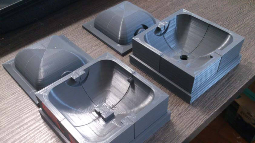
Here is a 3D printed mold for the tyres of the car. It is printed in flexible TPU. It's a first try, and it seems easier to use as it is flexible - the issue might be the risk of deformation as it is pressed.
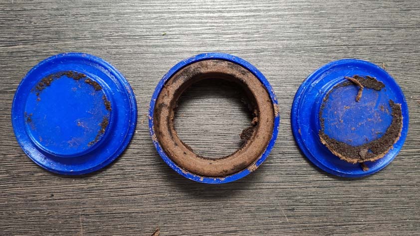
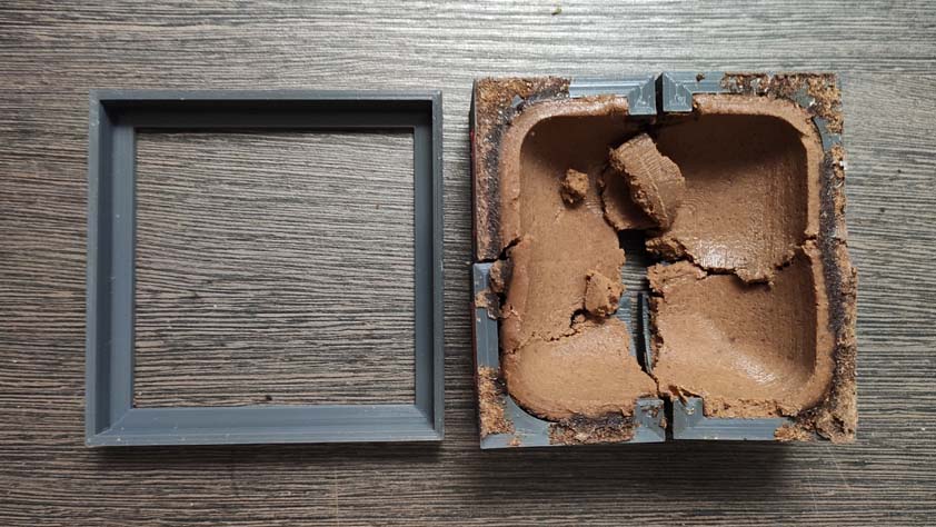
Opening the mold + 36 hours later : here are the demolded parts.
The tyre got deformed, and the junctions details are far damaged, the mold should get some modifications in order to divide it in smoother shapes.
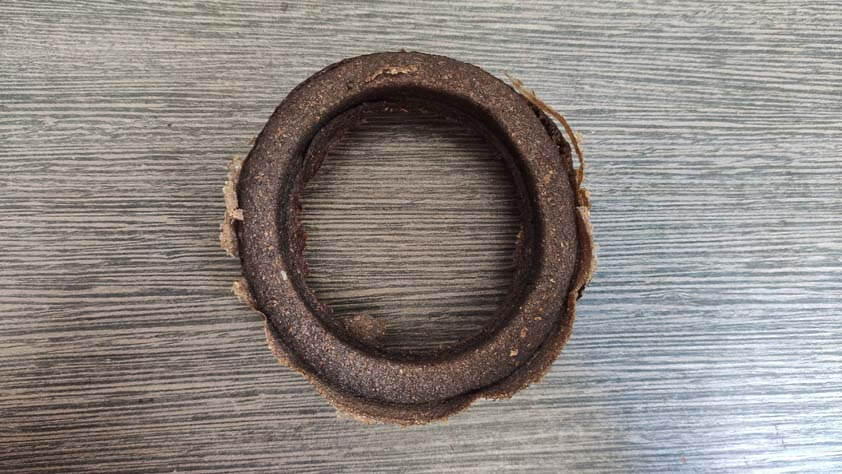
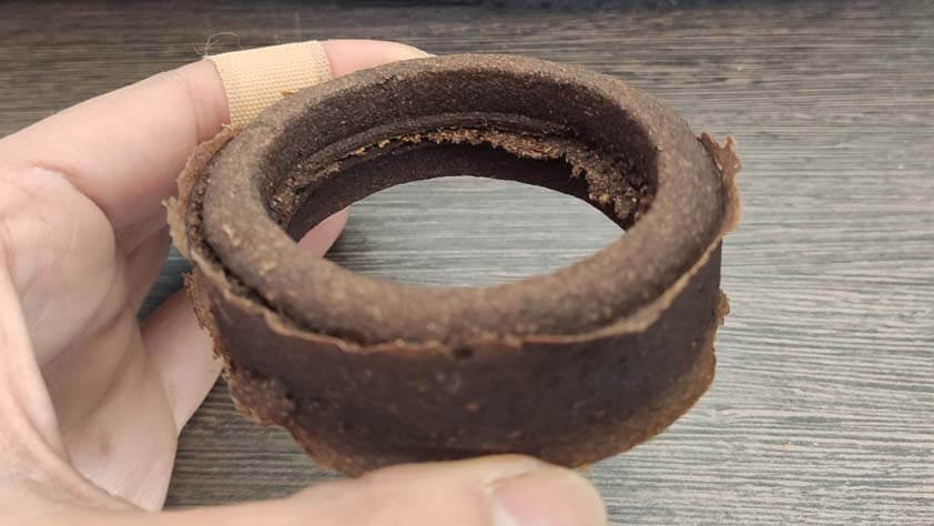
The body part gor deformed as well, I think the mixed composite had too much water in in when I put it in the mold, and that evaporation is causing this - but I can't be sure. Here again I will simplify the mold shapes so it is easier to demold without damaging it. I could also print a thinner mold with holes, to replace the first mold when it has to be removed. This might be useful in order to maintain the shape of the final piece while it has to be opened to dry.
▸ Breadboard Prototyping
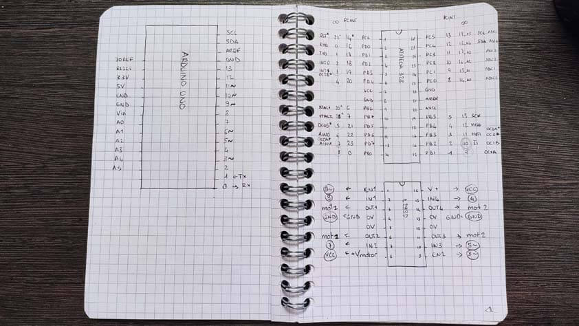
During Week 12 I made a circuit composed of 2 dc motors, and a servo motor. Such a board is what I need for the drawing car. The image below is a sketch of the board I'am using and their pins. As I worked on an Arduino Uno, I need to "translate" my pins to the AtMega328p pins.
Here is the final circuit :
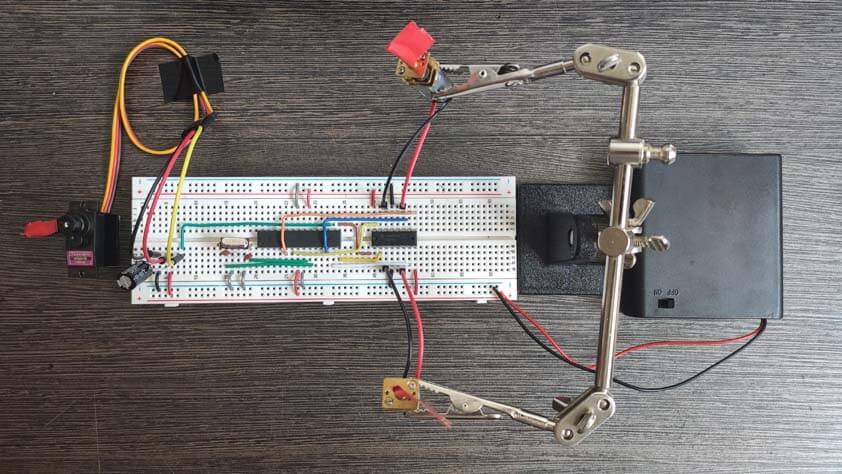
Here is the final circuit working, I am using a 6V power supply, it is not enough for the motors, but is works as a demonstration :
I upgraded the breadboard with orange wheels and taped a pen to the servo motor, let me present you the Drawing breadboard :
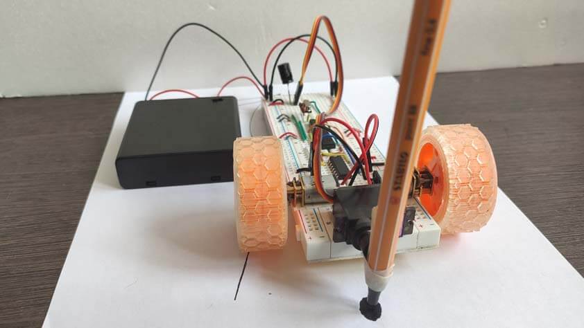
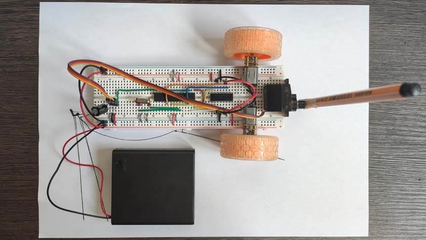
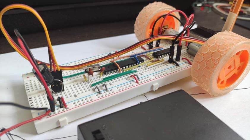
Here it is moving :
▸ PCB Making
I designed a board for the drawing car, by using the circuits I made on breadboard and translating these into a PCB, by using EAGLE. I forgot importants component in my first attempt, such as a resistor for the rest pin, and capacitors for the microcontroller. Following Jonah's advices, I added other components to secure the board polarity.
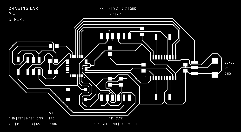
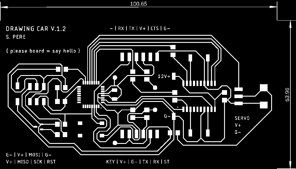
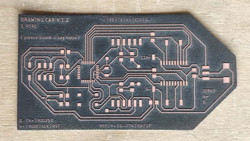
Here is the final circuit schematics for the drawing car, I use several 0 Ohm resistors as jumpers.

▸ Lasercutting & Soldering
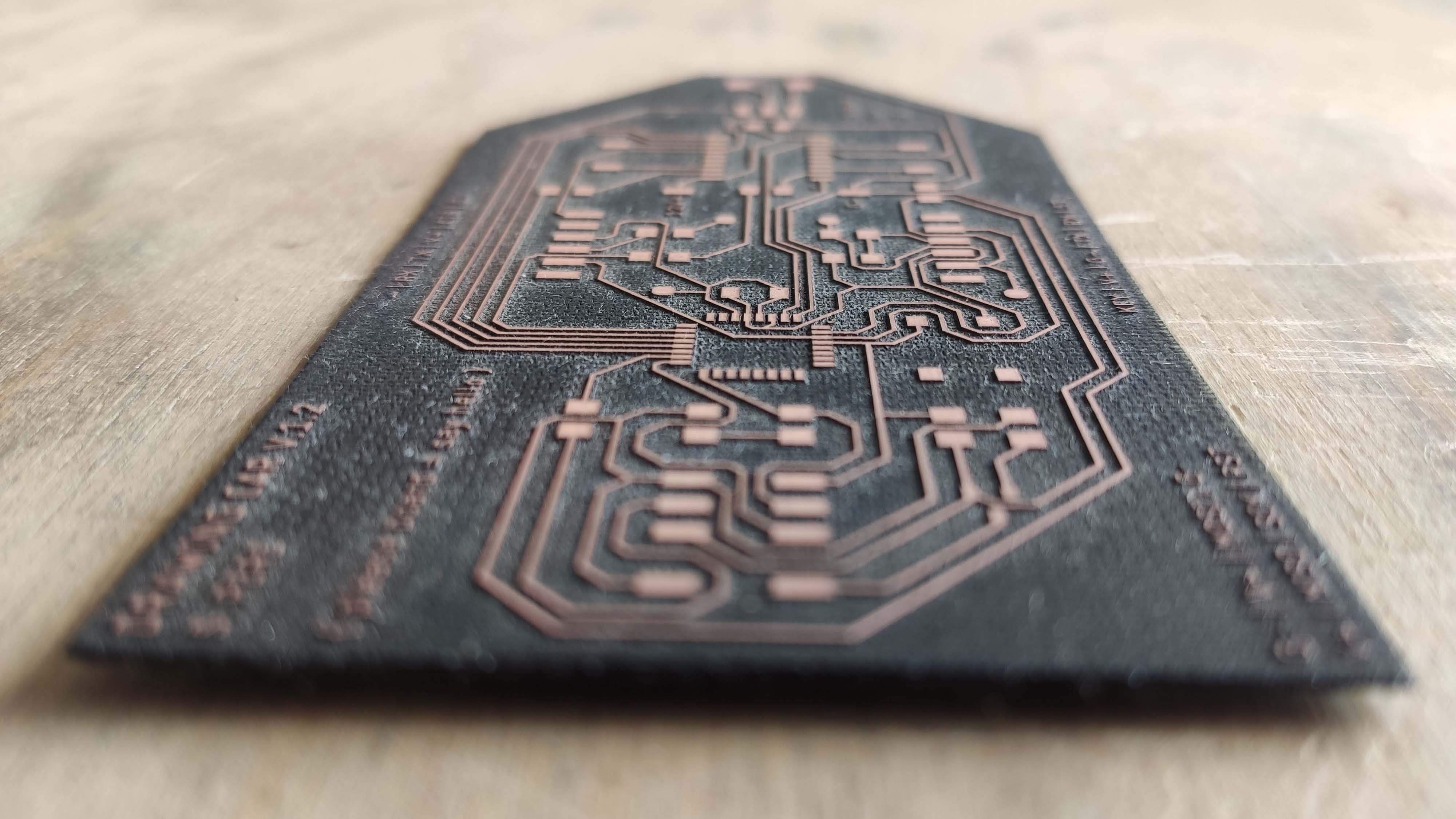
Here is the laser cutted board for the drawing car, using what I learned from my previous errors in the PCB making process, this board came out well !
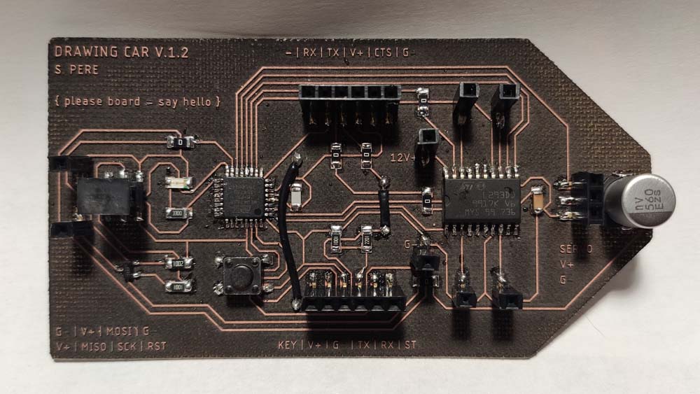
After checking the board with a multimeter I could solder it, and here is the result.
▸ Programming and testing
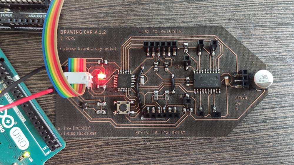
In order to make it work, I wrote a kind of incantation on the board.
Then I used the Arduino IDE to program it, by using an Arduino as an ISP, and a second Arduino to power the Drawing Car board. I compiled the Blynk example program on it, and it worked !
In order to test the motor I designed motors and servo motors holder integrating the board.
This step is useful, the board is much bigger than I expected and my original design is not adapted anymore. I Also need to integrat a system to lift-up the pen.
I uploaded a code to control the motors in one direction at a time, but unexpectedly, the motors are only moving in one way, as if the motor driver wasn't doing anything. Like shown on the video below.
I uploaded the code to control the car with the controller, through the HC-05 bluetooth module, in this configuration the motors are actually being controlled. What is unexpected here is that one motor is only turning forward. Here is the video :
▸ Arduino test code to control 2 dc motors (Zipped)
▸ Drawing Car board files (zipped)
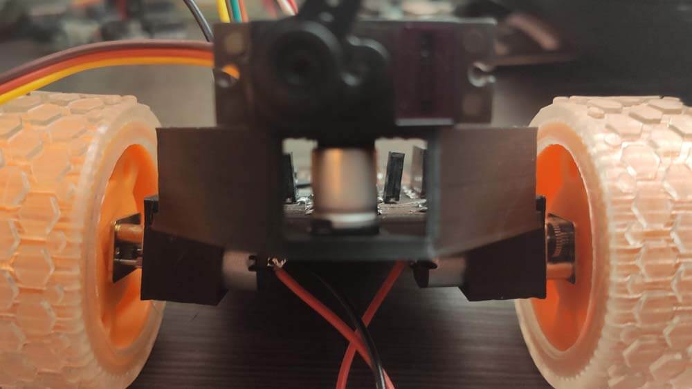
▸ Prototyping & Integration
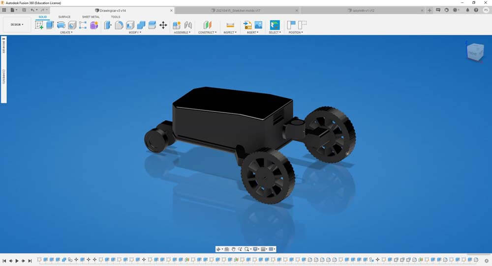
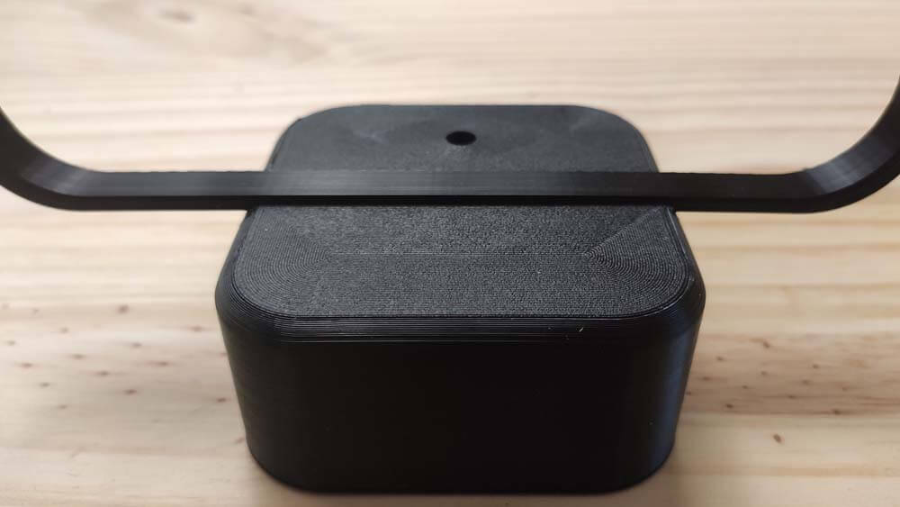
As the Blow Controller, the shape is totally different from the initail idea proposed, these first sketeches were an ideation and I was not aware of the size of the PCB, plus I wanted to try something else, so here it is. As for the controller, I did not think enough about the battery integration, so I will have to resize the body. Also, I have to find better settings to print the top boday, as the support leaves marks on the surface. But printing it in the other way around would use way too much filament, much more thant the objetc to print itself. So... I will test things.
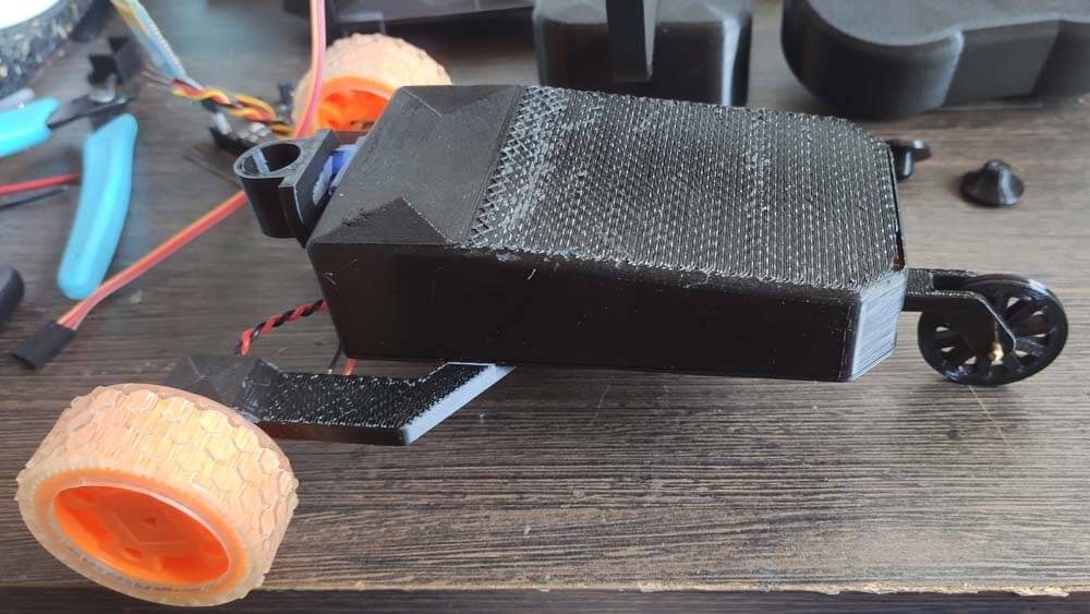
So, here is this Drawing Car on Fusion 360, print is coming.
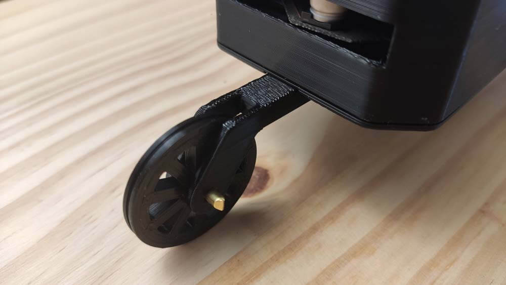
Print is ready to be assembled.
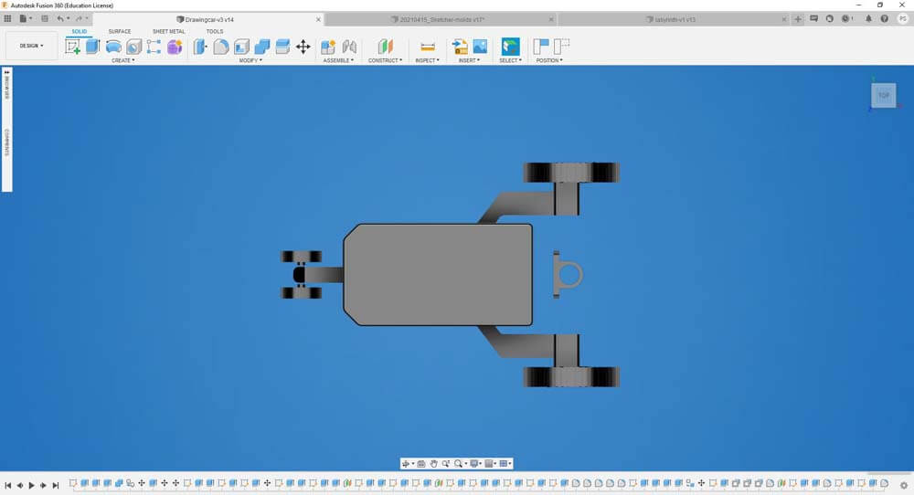
It needs modifications on the frame so the back wheel is actually "free-wheeling" to follow the directions.
Also, I havE to think of integrating the wires in the frame.
I modified the labyrinth model in order to make the frames slighty wider in order to create a safe way for the wires. The Car's frame has a complex shape and the easiest way to 3D print it is surprising :
☛ Making the Labyrinth
PCB Making
Prototyping & Integration
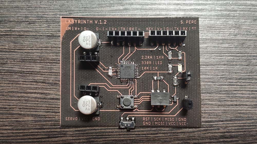
▸ PCB Making
I was late on my schedule to the final project, so I decided to design a board to control two servo motors, in order to be able to make the Labyrinth..
▸ PCB design using Eagle
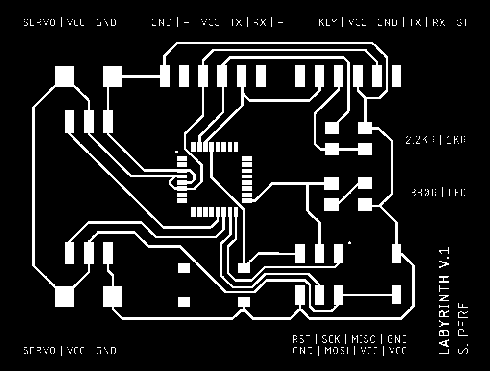
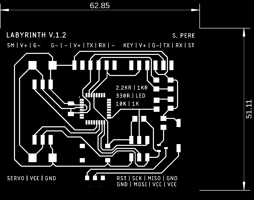
Here are the traces of the board, as for the Drawing Car, my first attempt is missing important components, the second image is more complete.
Here are the schematics for the Labyrinth board :

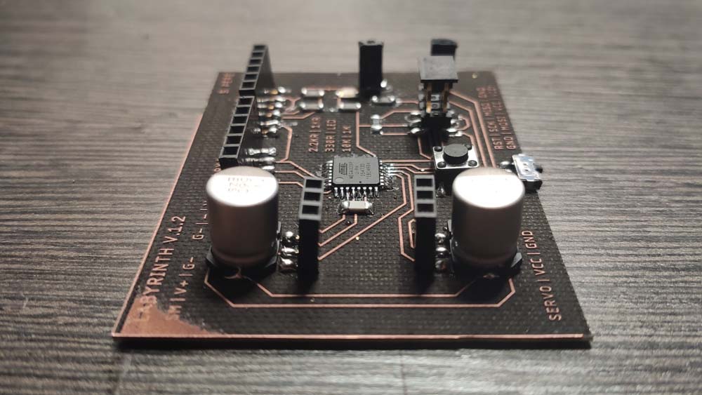
▸ Lasercutting & Soldering
In my first attempt in soldering, with my own solder iron, the one with a big tip and with a temperature that is not totally reliable, I burnt the traces, causing them to go off the board.
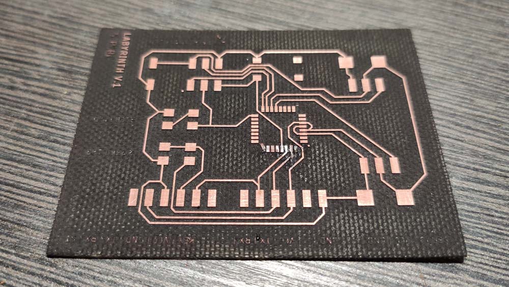
I lasercutted it again, this time the FR4 material was not totally plane so a corner is not totally engraved. Nevertheless, this issue is only esthetic and does not interfere with the circuit traces. Here is the board soldered :
▸ Programming and testing
As before, I use the Arduino IDE to program the board, I compiled the Blynk example program and it blinks fine.
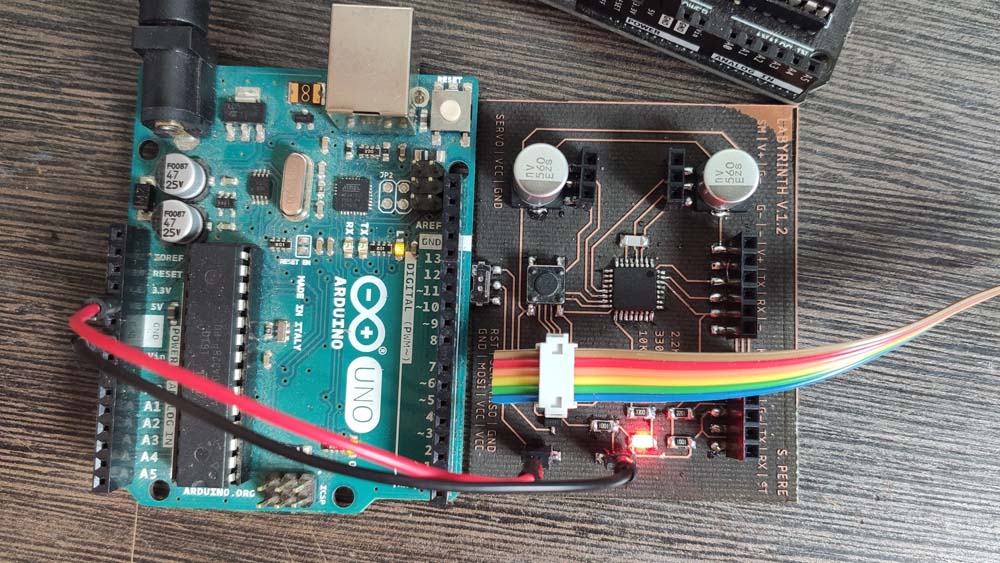
I uploaded a code to turn the servos to different angles, I used this labyrinth which was the first iteration of an old project. I made this using Illustrator, here are the Ilustrator and PDF files for this labyrinth.
▸ Arduino code to control 2 servo motors (Zipped)
▸ Labyrinth board files (zipped)
▸ Prototyping & Integration
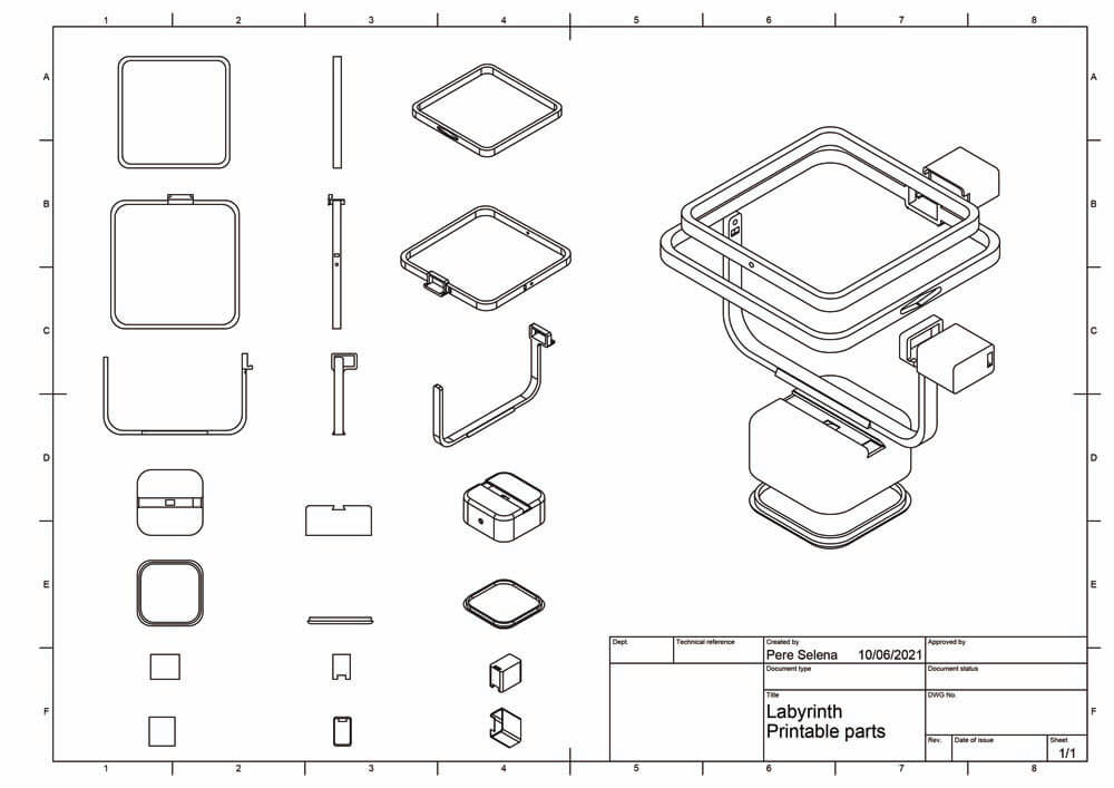
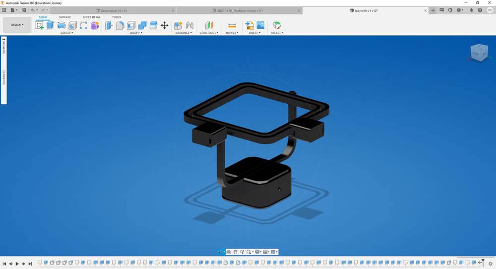
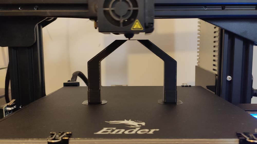
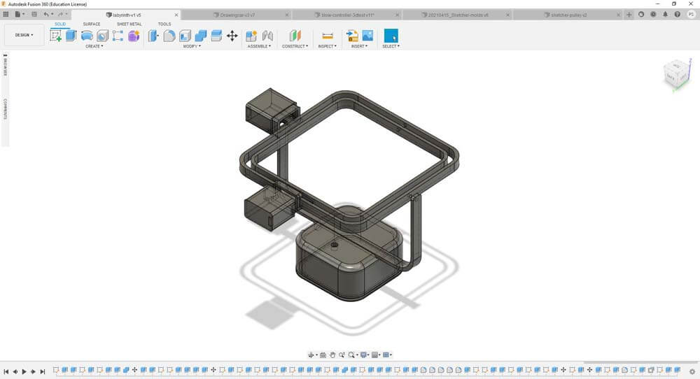
This machine went faster, because this is the last minute panic, a week before the final presentation. I designed the labyrinth "geometrically", a frame in another frame, in another frame. In order not to have wires to move the frames, I tried to integrate the servo motor in the frame axis. Great news is, it works, bad new is, I have to find ho to make it all hold tighter.
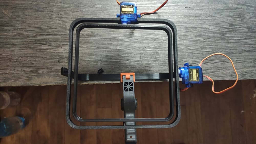
I modified the "servo holder" part on the frame, so the servo can be "pressed" in it. Then I designed "Caps" for hiding the servos.
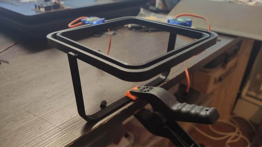
I printed this second version and added the "box" holding the labyrinth mechanism.
I modified the "servo holder" part on the frame, so the servo can be "pressed" in it. Then I designed "Caps" for hiding the servos.
I modified the "servo holder" part on the frame, so the servo can be "pressed" in it. Then I designed "Caps" for hiding the servos.
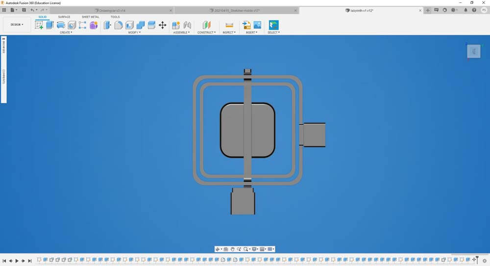
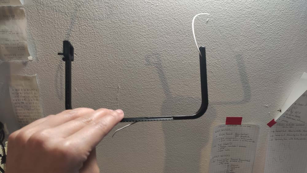
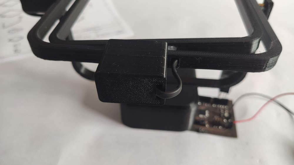
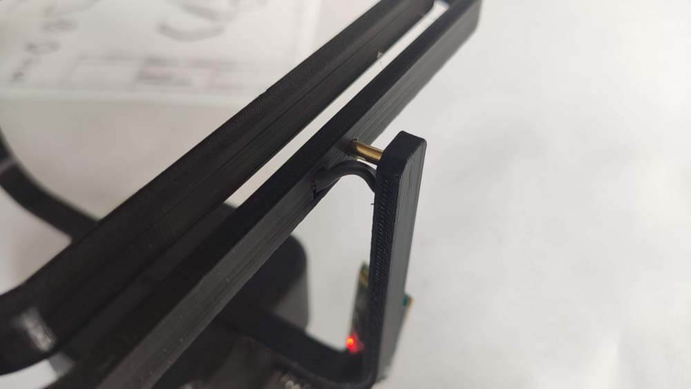
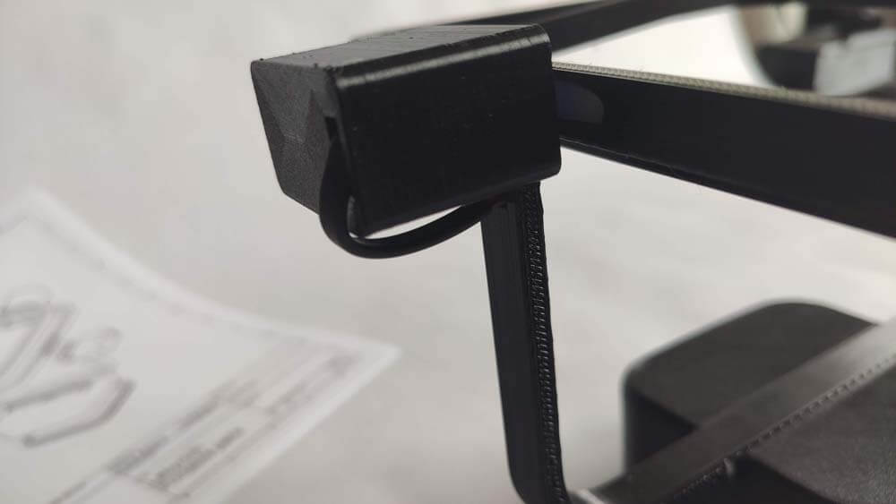
I redesigned the frame in order to manage the wire integration, the following picture shows three wires passing through the labyrinth's frame. This part was 3D printed with a support for the parts touching the bed only in Cura.
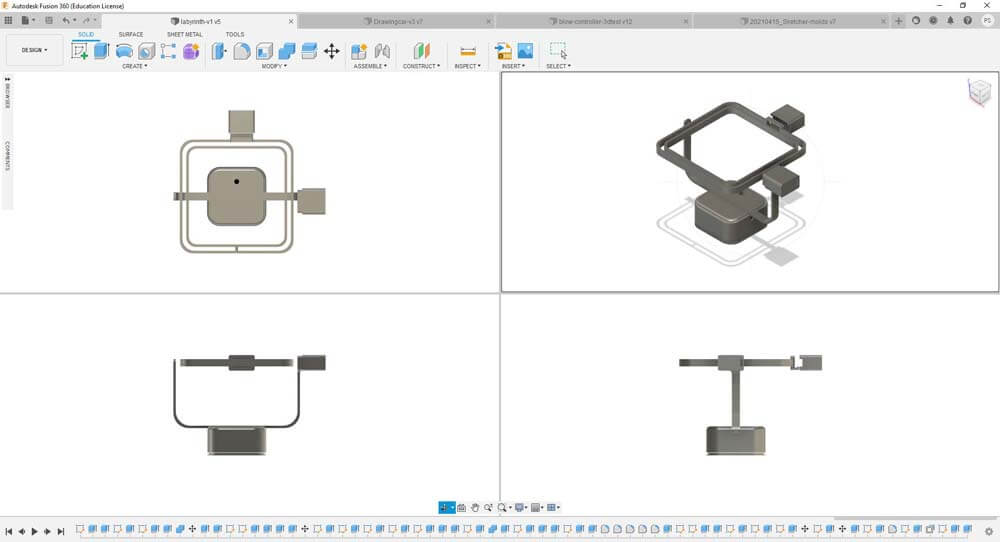
As this system was working pretty fine I redesigned the whole labyrinth so its design integrates the wire and they are almost invisible when the machine is assembled. The following pictures are details from this system.
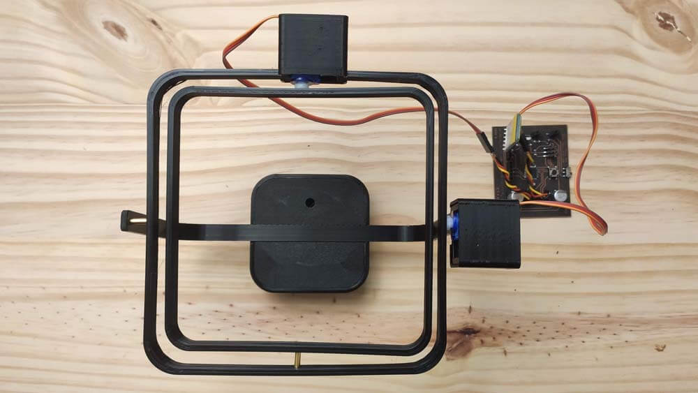
And here is the final result when the Labyrinth is assembled.
☛ Making the Drawing Machine
2D Design
PCB Making
Prototyping & Integration
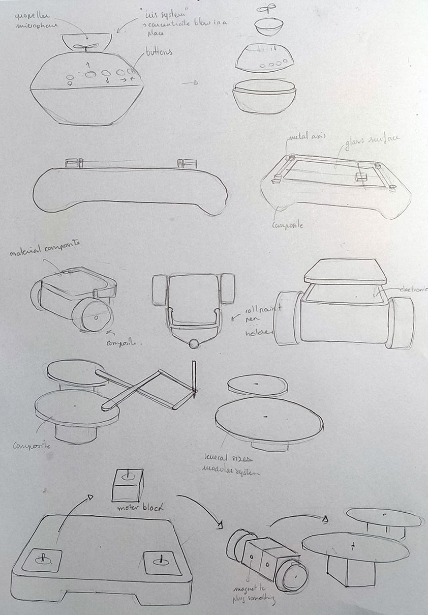
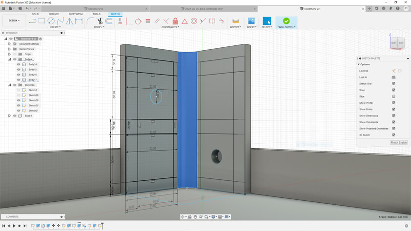
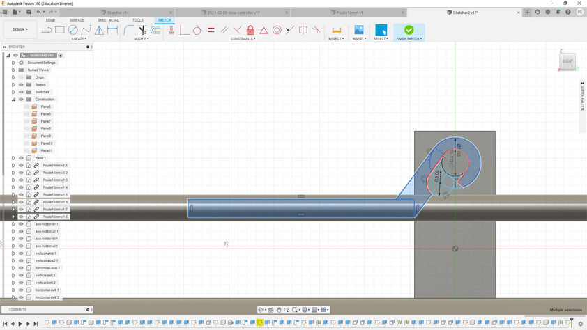
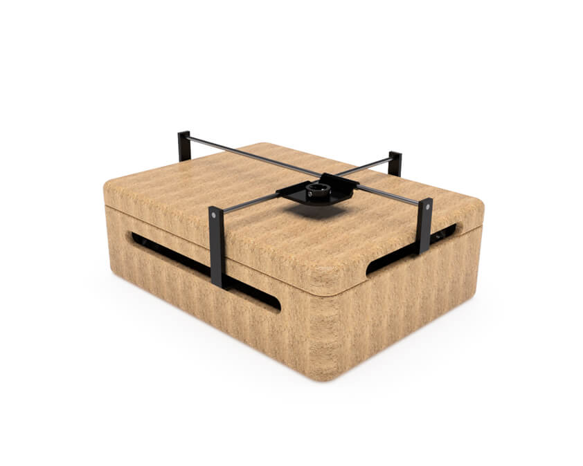
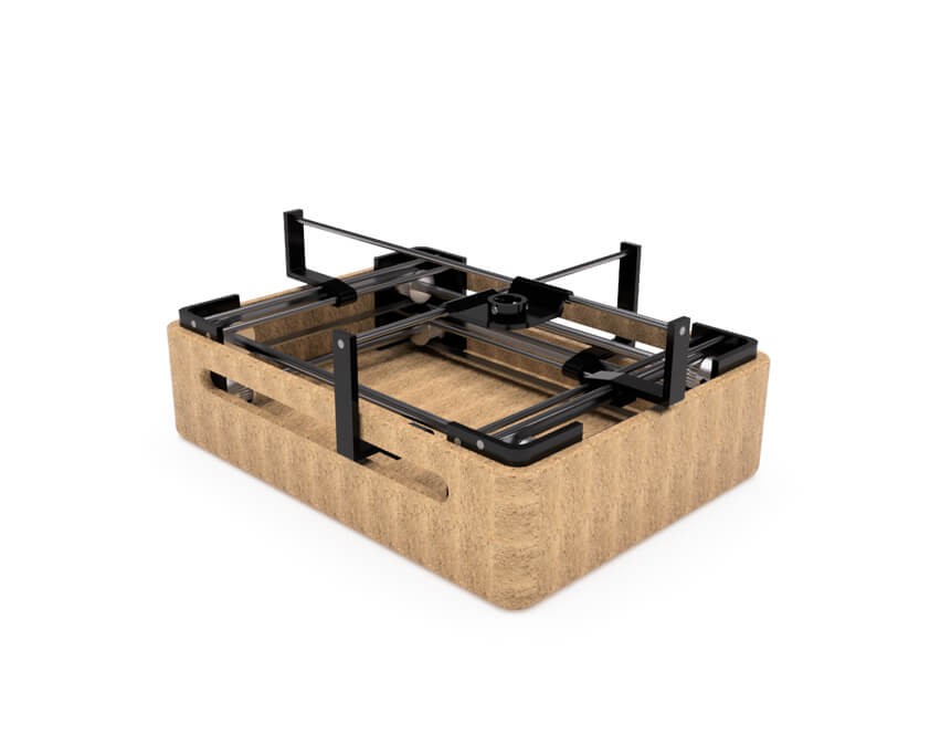
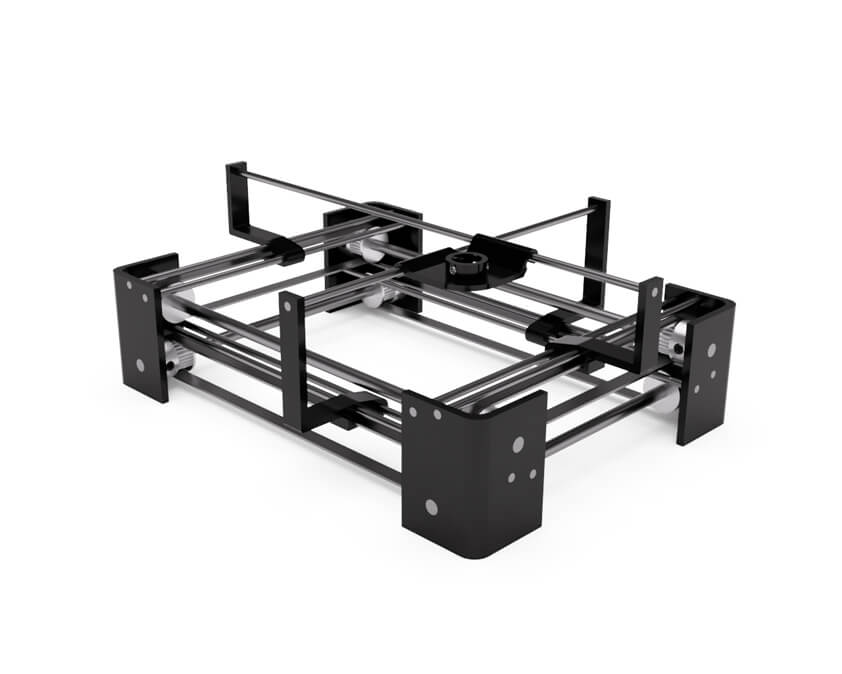
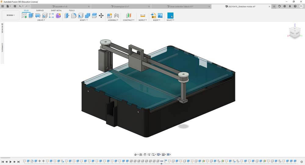
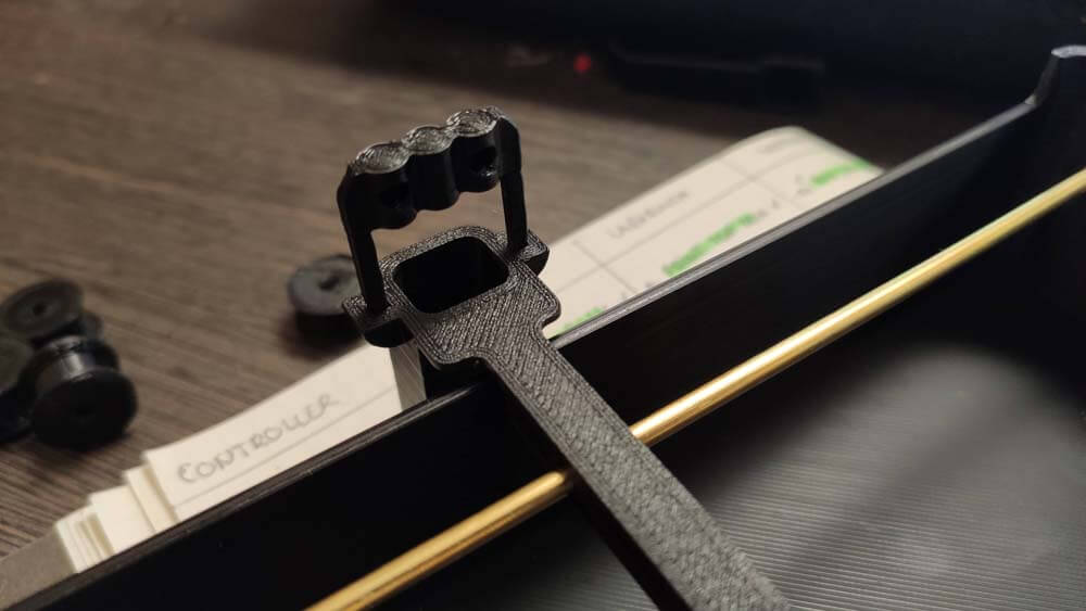
▸ 2D Design
During week 2 I imagined this simple system to remake th Drawing Machine. In this proposition, two perpendicular axis are carried by arms moving in parallel. The Pen holder is clipped on those axis.
Here is the history of the conception in Fusion 360.
I use sketches to make construction grids I can repeat so everything is symmetrical. I used constructions panels to adapt new components to my model, the last image is the pen holder profile.
I am really satisfied with these renders. 3D modeling is pretty satisfying and much more clearer than my 1 minutes hand drawing sketchs to convey a "mechanical" idea, it would have took me hours to draw a single proper view of it. It took me hours, but we can move in it and this is pretty exciting.
▸ PCB Making
▸ Prototyping & Integration
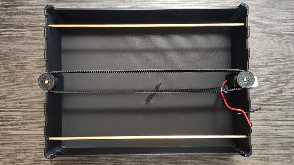
As time is running, I tried to simplify a lot this system, here is my second proposal for this one :
I printed the parts of the model above, but as for a first prototype, there's several things that are not right. However, here is the first test assembled :
I had to modify the horizontal axis because I made a mistake in the measures. But I didn't just changed that measure, I decided to remake it from scratch and founs a cool system, made by zooming a lot without noticing in Fusion 360. So useless in these proportions.
I redesigned the main "box" of the sketcher, and I wanted to share this calibration of the Ender 3 3D printer, what you see is not only the bed, but the first layers that can be confused visually with the bed as it is almost perfectly plane (Yes I am very staisfied to finally be able to calibrate this machine properly !) :
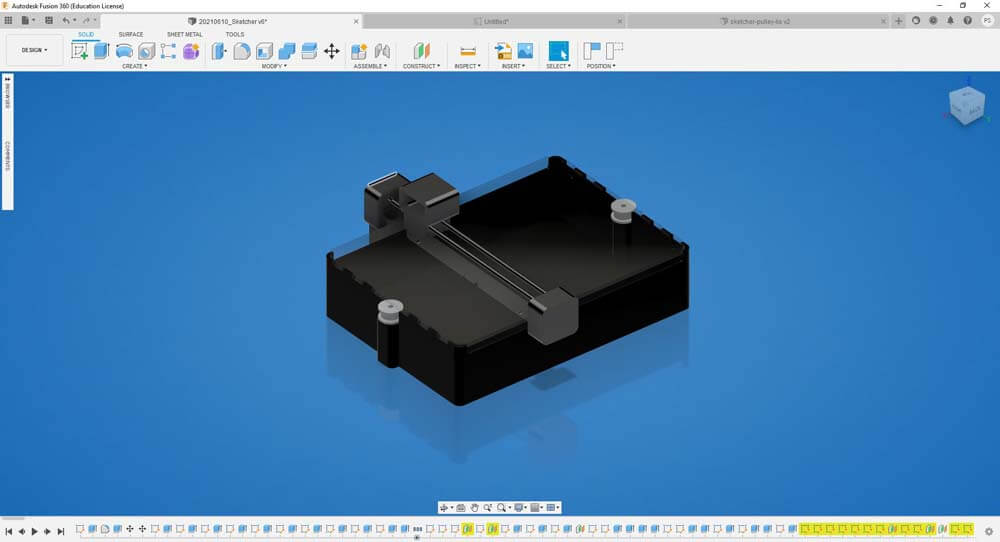
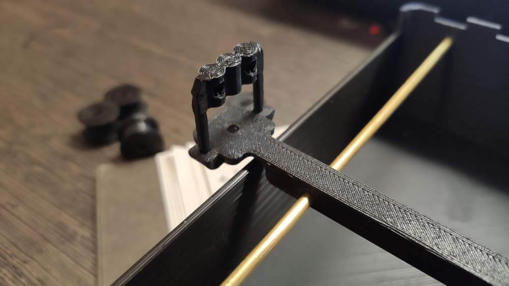
I redesigned the useless axis by trying to intagrate the systems at the same time. The test assembly looks like that now :
Here is the "internal" very simple assembly.
I still nedd to modify the second axis to gain precision and stablility, where the timing belt is clipped is actually preventing the axis to move with balanced.
☛ Wireless Communication
▸ DC motors remote control using HC-05 bluetooth modules
During Week 13 I established a bluetooth comunication between my board by using a HC-05 module. I used several tutorials, and this one mainly in order to use this connection between the module to control motors with a joystick.
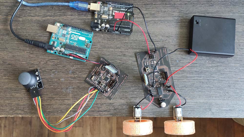
There will be a controller board with a joystick and the HC-05 Teacher, and another board with a motor driver and the HC-05 Student.
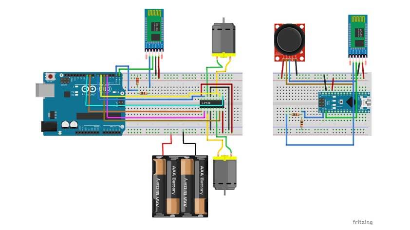
The Teacher board is composed of :
- 1 * HC05 bluetooth module configured as a Teacher at the address of the Student
- 1 * Joystick
- 1 * Arduino Nano
- 1 * 1K resistor
- 1 * 2K resistor
- USB for serial communication
- Breadboard and Jumper wires
The Student board is composed of :
- 1 * HC05 bluetooth module configured in default mode, binded to the Teacher
- 1 * L293D motor driver
- 1 * Arduino Uno
- 1 * 1K resistor
- 1 * 2K resistor
- 2 * DC motors
- USB for serial communication
- Breadboard and Jumper wires
▸ Arduino codes
These codes were provided on this great tuorial.
Here is the Arduino code used for the Teacher board : HC05-Joystick-Teacher-code.zip
Here is the Arduino code used for the Student board : HC05-Car-Stud-code.zip
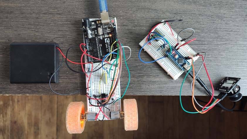
Here is a video of this set up in action, almost. Here the Teacher board is powered using USB, at 3V. The Student board has to power supply, the arduino is power supplying the bluetooth module, while a 6V alimentation is powering the motor driver. It needs more power but I can't provide more safely at home. But some good indicators are that, in one direction, it is clearly moving, and in the others, I can hear discrete motor noises. Communication seems to be happening.
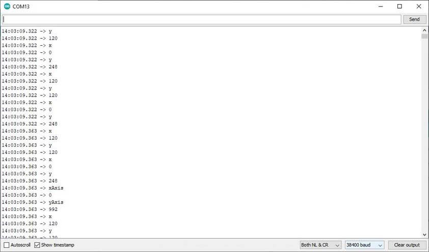
I used the serial monitors to visualize the communication between the modules, it appeared that they are talking, but the commands are lost in the translation. While the Teacher modules is sending the joystick position's values, the Student module prints not expected values.
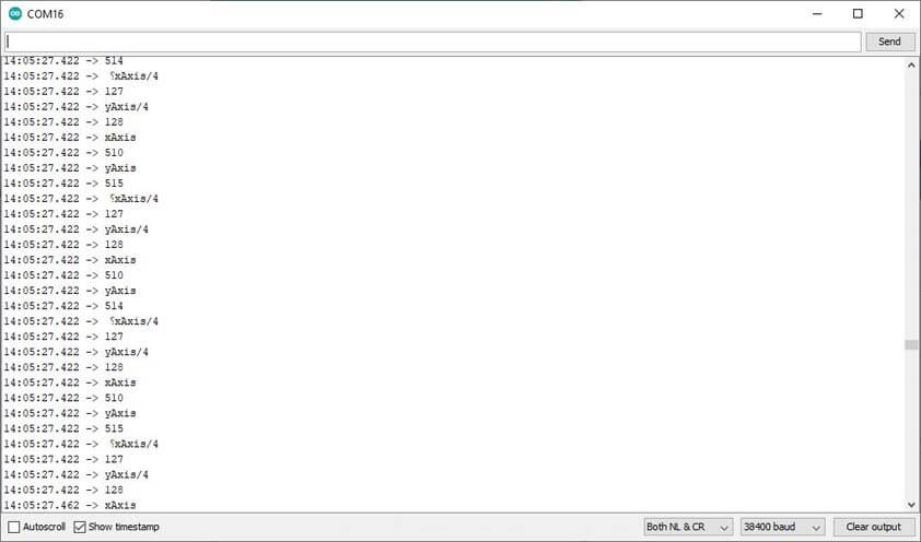
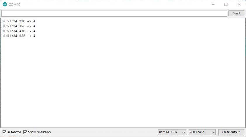
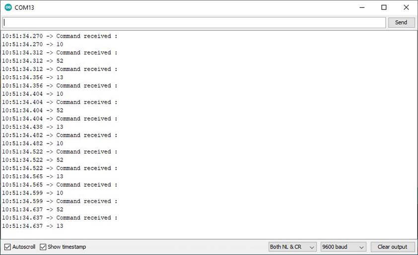
I tested several things in the code, what solved my issue was that even though I documented above that the baudrate for this module is 9600, the code I was using was set at a 38400 baudrate. The following images show that at the right baudrate communication is better, while the Teacher is sending the "Serial.println("4");, the receiver prints "10", "52", "13", which means "10 : New line", "52: 4", and "13: carriage return".
I used this ASCII table to translate these datas.
The next video shows that it is working better : the motors are moving in the expected direction, still, the motor board is under supply, and the result is not super reactive.
▸ Arduino Student-Teacher code to control 2 dc motors through HC05 modules (Zipped)
☛ Using my boards
This is an update published on june the 1st.
▸ Circuit Setup
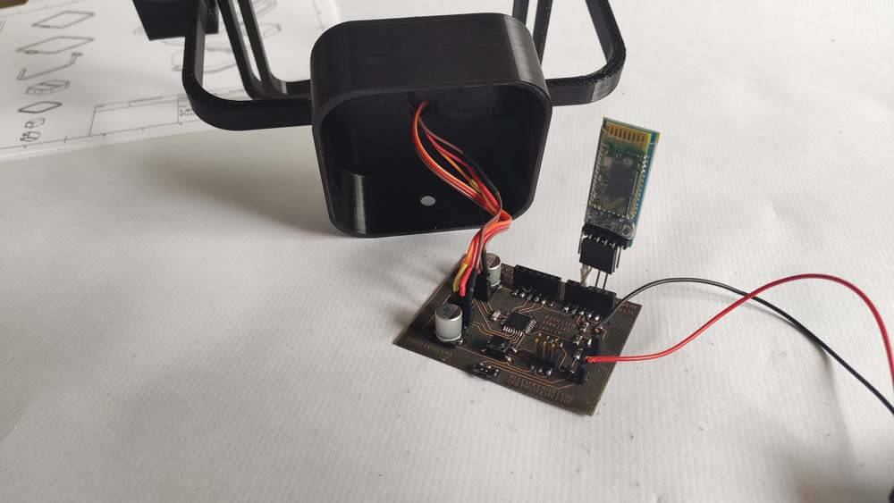
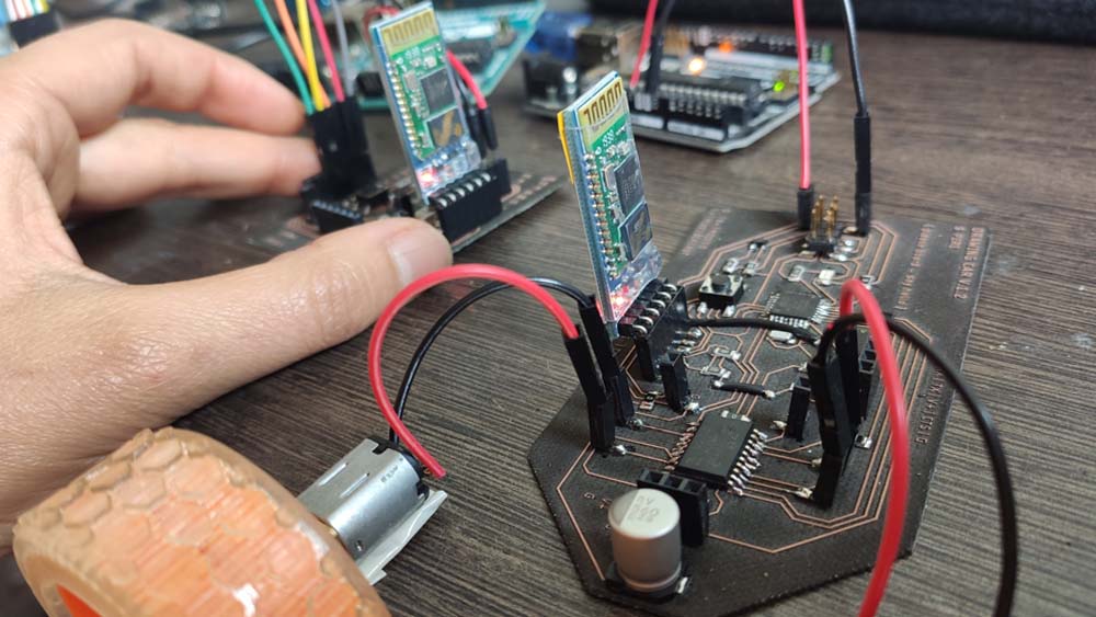
Finally, I tested the programs with my boards. I am using an Arduino as an ISP, Arduinos to power the board, and batteries to power the L293D from the Drawing Car.
I used the HC-05 Bluetooth modules I used before, and it they connected together. Here are the codes I used they are similar to the ones displayed above, but I made modifications to light up the LED. Also, for now I can't controle the servo motor. I didn't find why yet. This part will be updated in the Final project.
Here is the video of the first test. As the pins were changed but not the code (when I filmed this, the code zipped above is modified to the right pins). It is working, but there is still a delay between the command sent and the command applied.