Week 13 : Networking & Communication
☛ Individual Assignment
☐ 1. Design, build, and connect wired or wireless node(s) with network or bus addresses
☛ Group Assignment
☐ 2. Send a message between two projects
☛ Connecting two boards through I2C Connection
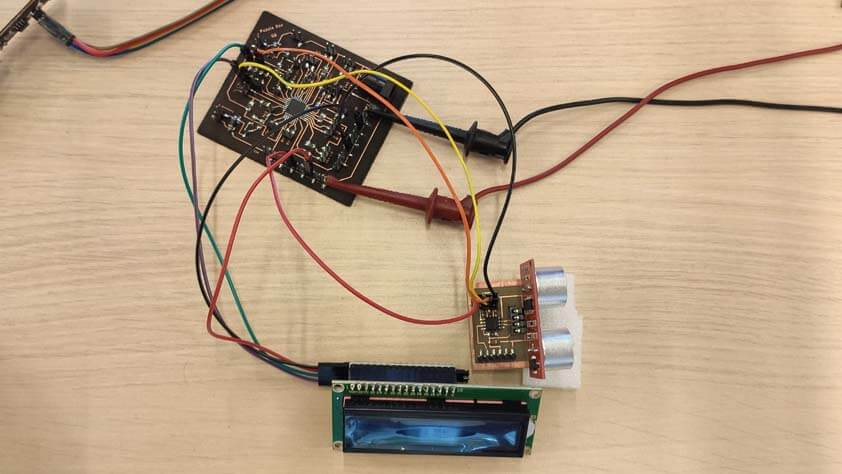
As a group assignment we sent a message from Ambroise's board, with a Distance sensor, to Quentin's board, with a LCD display. They are communicating through I2C connection.To do so, a board's role is defined as a Teacher, and the second board is defined as the student, we have to connect the SDA and and SCL pin from the master board, to the SDA and SCL pins from the student board.
In the codes, we will use the Wire Library, the Teacher board, in this case the Distance sensor one, will transmit the values he is sensing to the Student board. The second board is linked by an address to its Teacher, his role will be to wait for data to come from the other board, and to print them on the LCD display.
Here is the video of the setup :
☛ Testing 433Mhz RF Modules : RX480E-4 & TX118SA-4
I bought these RF transmitter/receiver modules and I found this tutorial which explains the basics to use them.
Initially I thought I could use these modules in order to "pair" the controller from my final project to control the drawing car with it. After completing this tutorial, I don't think I can. A learning button is used to pair the emitter with a receiver that is accessible, the learning button has to be pressed 8 times to wipe out the memory from the transmitter, its led should blink 7 seven times. After this step it is possible to pair it with a receiver. These modules have 3 modes of operation that can be choosen using the learning/pairing button on the transmitter :
- Momentary mode
- Toggle mode
- Latched/interlock
When using LEDs to test these modules, the momentary mode allows a momentary connection, the LED is High when the corresponding button is pressed, then low as soon as the button is unpressed. When using the Toggle mode the LED stays high after one push, and has to be triggered again to become low. The last mode allows one "channel" at a time to be open, if Led 1 button's is pushed, the led becomes high, then if Led 2 button's is pressed, Led 1 is low and Led 2 switches on. To replicate the circuit from the tutorial I needed :
- Jumper wires
- Breadboards
- 2 * Arduino Uno (as 5V power suppliers)
- 5 * LEDS
- 5 * 330Ohm resistors
- 4 * Momentary push buttons
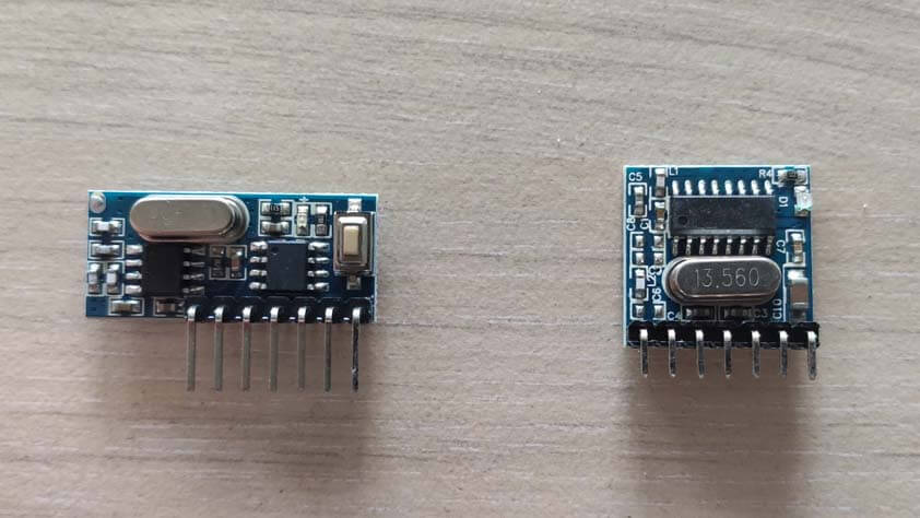
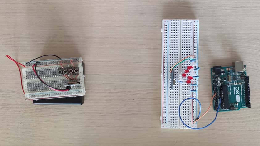
Here are the modules and their respective circuits, I used arduino's board to power the modules with 5V. I took those images from the tutorial linked.
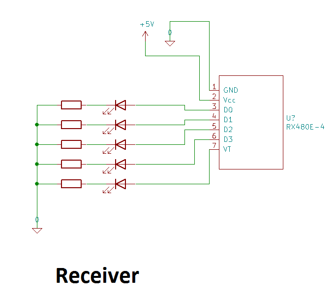
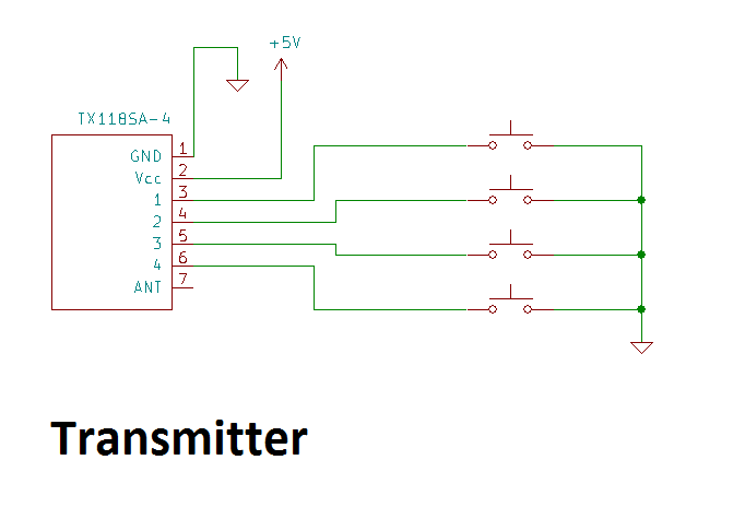
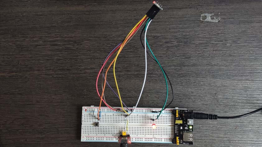
Here is a video resulting from the tutorial linked above, I am testing the momentary mode at a short range distance. I don't understand why two Leds are switching on at the same time, plus I had to modify the Leds order on the breadboard as they are not in the right order on the pcb.
Without using the antennas from these modules, I could use the transmitter up to 6 meters away from the receiver.
☛ Testing WiFi Module : the ESP8266-01
Another module I bought some time ago because "it could be useful one day", the EPS8266-01 module. It is a WiFi module that is cheap and it can be used with an arduino, or be programmed itself. It seems to be a very useful module and I chose to follow a tutorial to get to know him better - this week is really complicated because I really don't know how to proceed. So here is ESP8266 WiFi Module for Dummies tutorial.
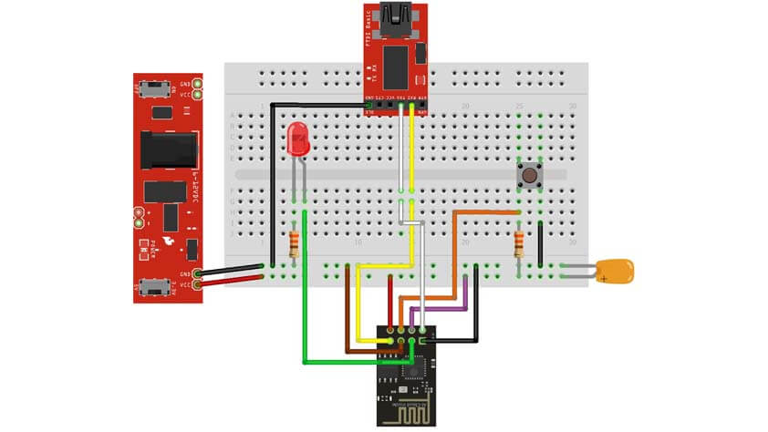
▸ Circuit Setup
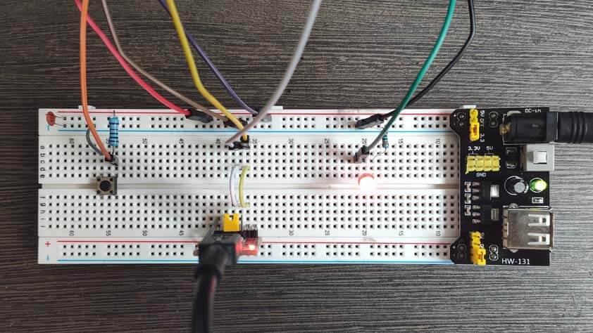
It took me time to make this circuit because the ESP8266-01 should not be supplied in 5V in order not to damage the module, there was various options to power supply it. I chose one I had never tried before : This is the first time I am programming a board by using a FTDI programmer (I bought this one years ago because a friend told me I would need it someday, this day is today), and this is the first time I use a breadboard power supply module. This power supply module is called the HC-131, and so far it is very handy as it can supply 3V or 5V one each side of the breadboard separately, or both, it means that it could supply 5V and 3V on the same breadboard. To follow the tutorial I used those parts :
- 1 * WiFi Module ESP8266-01
- 1 * LED
- 1 * 330 Ohm resistor
- 1 * Momentary switch button
- 1 * 10KOhm pull-up resistor
- 1 * 1uF decoupling capacitor
- 1 * FTDI programmer
- 1 * Breadboard power supply module
- Breadboard
- Jumper wires
The GPIO 0 pin has to be linked to GND while the board is being programmed, and it has to be unplugged when using the ESP without the FTDI.
The CH_PD pin has to be linked to the VCC.
The reset pin is linked to a switch button and a 10k pull-up resistor, it has to be pressed to reset the ESP before programming it.
Here is the block diagram I made for this circuit :
When the circuit is power supplied in 3V and connected properly, the ESP red led switches on, and the blue led blinks one time.
▸ Arduino IDE Setup
When the circuit is ready, the Arduino IDE we have to import a new board library, and several libraries for the ESP8266, most importantly the ESP8266WiFi.h that is used in the code from the tutorial that we will use.
- The link to add the ESP8266 package in the board manager (To copy paste in IDE > File > Preferences) : "http:// arduino.esp8266.com/ stable/package_esp8266com_index.json". When this link as added to the Preferences window, it can be added in Tools > Board Manager.
- The link to the ESP8266 Github, with libraries and exemples for using it : here
- Another link for the ESP8266 librairies, as the first one had missing files in it : here
- A link to most of the Arduino libraries, because when working on this project, some of my libraries came up as invalid and I had to download these again.
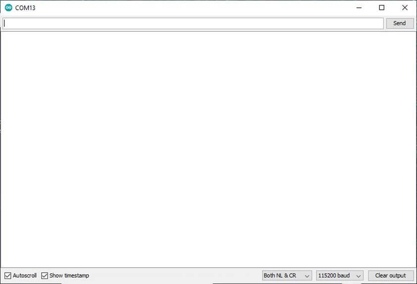
- Set the Serial Monitor baud rate at 115 200, for communicating with the ESP8266
▸ ESP8266 Arduino Code by TonesB
Here is a link to downlad the zipped arduino code ESP8266WiFi.zip.
In order to make it work as it is, the SSID and the Password have to be modified with ours.
Also, to make the programming part possible I had to reverse the Tx and Rx pins, when it worked this message appeared in the serial monitor.
When the code is uploading, the blue LED is blinking, as the board is programmed, the GPIO 0 pin can be unplugged from the GND.
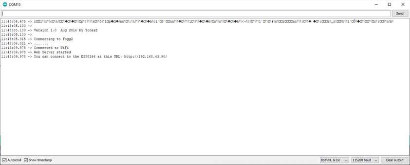
I opened the URL provided and I could control the LED from the web page.
☛ Testing the ESP8266-01 2
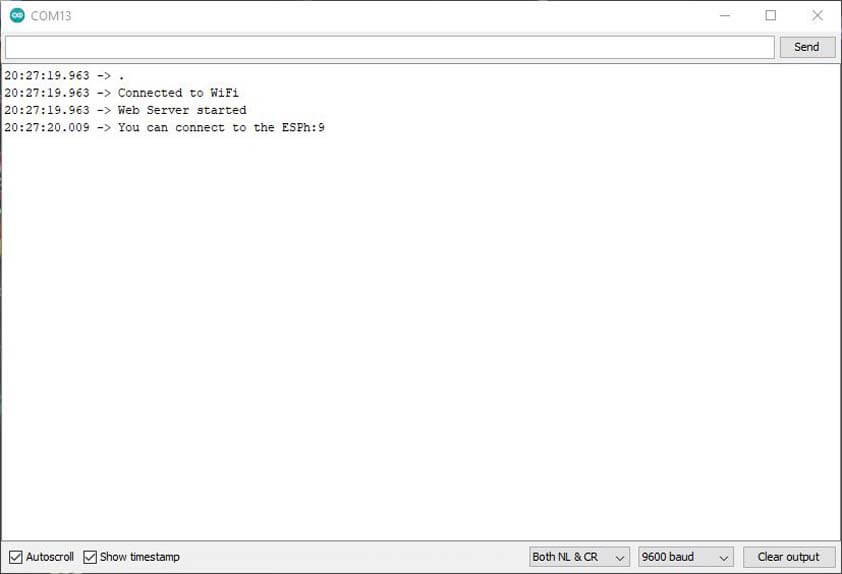
Next I tried to reproduce this tutorial to control 2 servo motors on a browser with the ESP 826601 and an Arduino Uno.
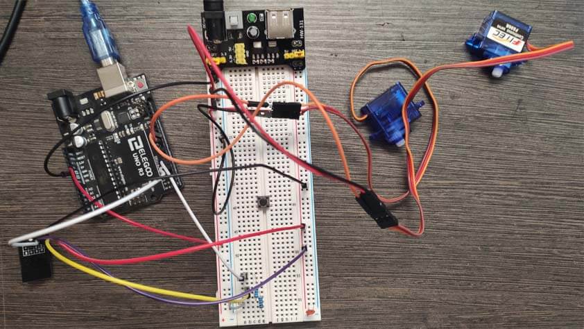
The tutorial was only using the power supply from the arduino, I was a little bit suspicious about that after my readings in order to use this module, but as I'm not mastering all these things I decided to follow the tutorial "letter by letter". It didn't work so I rework the circuit in order to only have to plug the servo and RX, TX pins for the serial communication. This way, I show some kind of living form in the serial monitor, but nothing happened next. As I resetted and restared everything, nothing more would happen.
To be continued when I will find more time and patience. I linked the tutorial above If you want to give it a try.
☛ Testing the Bluetooth module : Student Communication
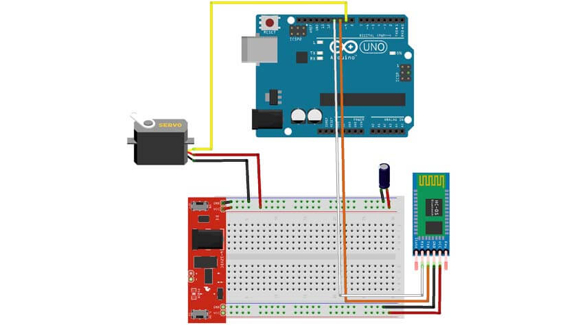
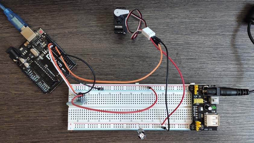
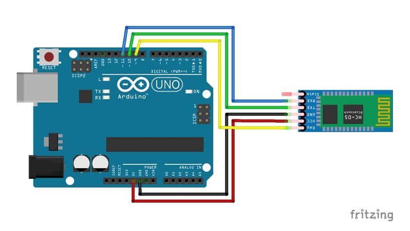
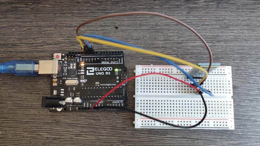
I tested the HC05 Bluetooth module, I followed a tutorial throuh which I learned to control a servo motor using bluetooth through an application made on MIT App Inventor. The great instructables tutorial is right here.
▸ Circuit Setup
The components needed are :
- 1* Arduino Uno
- 1* HC05 Bluetooth module
- 1* Servo motor (not a continuous one)
- Breadboard & jumper wires
- 5V power supply
Some important notes before continuing are :
- To remove the VCC wire from the HC05 module before uploading, in order not to damage it.
- The HC05 module bluetooth ask for a PIN to pair with it, most of the time it seems to be 1234.
- Connect the Arduino board through USB in order to see the serial communication.
- If the servo motor is behaving like a wild horse you can add a decoupling capacitor between its VCC and GND pins, and if it persists take another servo.
Here is the block diagram circuit for this project :
▸ Arduino code
I used the code provided by the author of the tutorial :
▸ Making an application on MIT inventor App
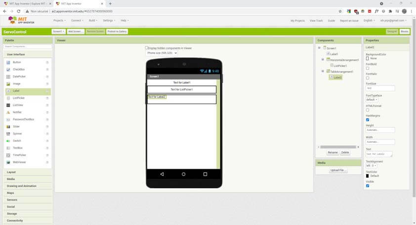
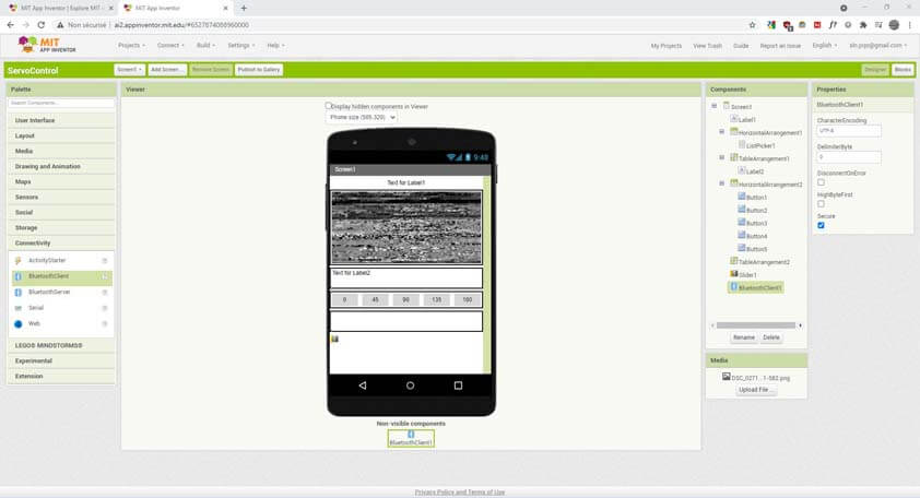
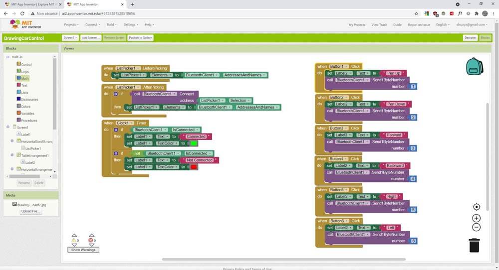
Here I am using the MIT App Inventor to conceive an interface to control the servo motor using the bluetooth connection established with the HC05 module. The app is composed of two main parts, the Designer mode, and the Blocks mode. In the first mode, we have to select the visible and invisible elements composing our app, we manage how they are linked by block coding in the Blocks mode.
In the images below, I select User interface modules and layouts to create the visual structure of the application, and I add a BluetoothClient, this component will allow my phone to connect to other bluetooth devices. It uses the Serial Port Profile for communication.
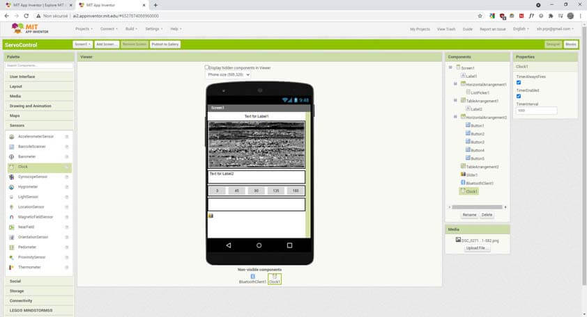
In the following images, I am first adding a Clock component, this is another invisible component (like the BluetoothClient) that uses the internal clock of the phone to provide "timing".
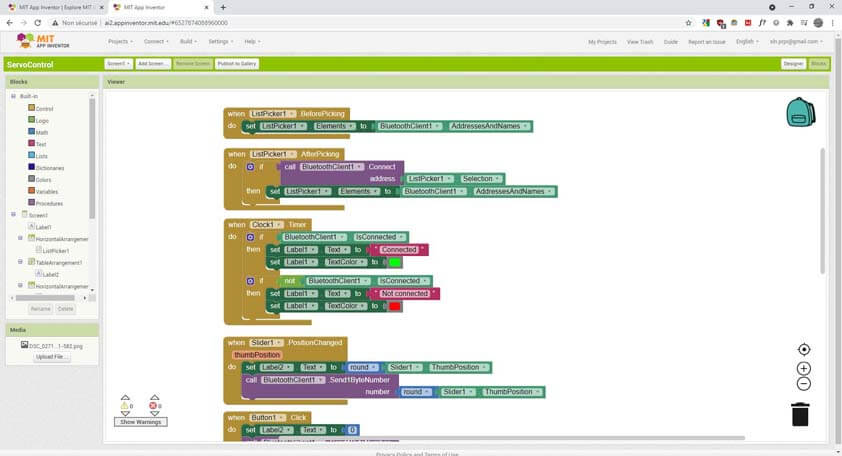
The second image shows the Blocks mode and the blocks responsible for the bluetooth connection between the phone and the HC05 module.
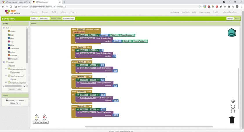
The first image here shows the messages sent to the bluetooth module when the slider is moving, or when buttons are clicked.
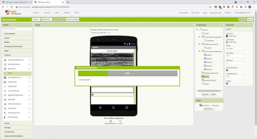
Finally, when the design and the blocks of code are set, we can built a .APK file and install it on an Android device. (An application from MIT App Inventor exists to test application without this APK installation, but it requires the phone to be connected to WiFi and I can't do that - internet issues - too bad, it seemed easier.)
In order to install the .APK file "installation from unknown sources" has to be accepted. And here is a screenshot of the application on my phone.
▸ Result
It didn't work as soon as everything was switched on. First, I didn't notice I was using a continuous Servo Motor, and it behaved "savagely". The second servo I used was always moving but on one side only. The serial communication shows 180 values only, while other commands are sent. I tried several things in the code, like mapping the values, but it didn't solve the issue. I tried with anoter servo, and it worked fine with it. I added a decoupling capacitor between the GND and VCC of the servo.

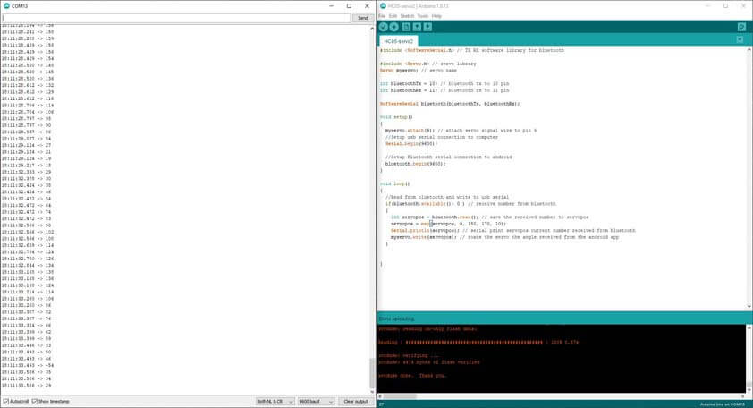
As I was using my phone to have acces to the App, I filmed this from my computer : I am first using the slider to change the servo's values, then the buttons, and the slider again.
☛ Testing the HC-05 Bluetooth module : Student Communication (Failed attempt)
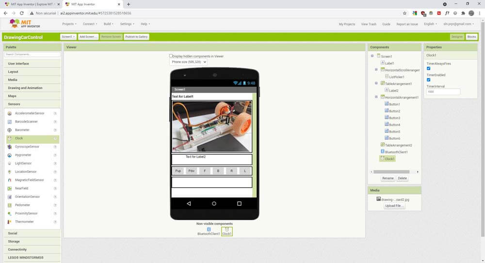
It was late, it was working just before, so I thought that I could replicate this process using my code and my previous "Drawing Breadboard" by adapting it with the one used before to establish the bluetooth.
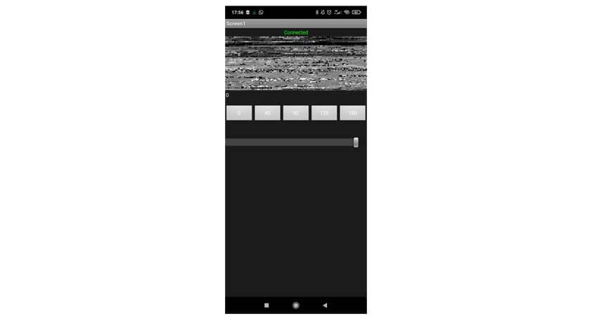
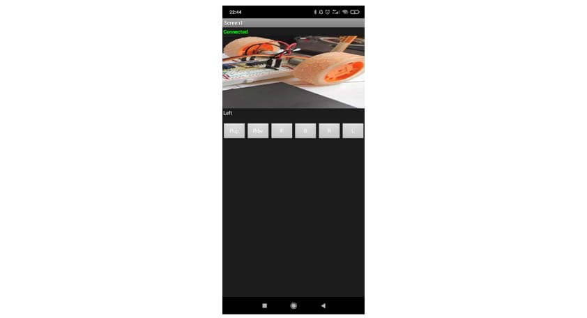
I used the template of the first app and added buttons to control the servo motor and the DC motors.
Here is the app looks like. I could establish the conection, as indicates the "Connected" on the screenshot below, but none of the commands worked. I couldn't recieve the serial communication (I need help on this part !) and so I don't know what the communication was like. I will go back to this later, I think the issue is in my code (DrawingCar-bluetooth.zip).
☛ Testing the HC-05 Bluetooth module : Teacher-Student Communication
So far I thought the HC-05 bluetooth module could only act as a Student, but I discovered that it has actually 3 operation modes, being a student is its default setup.This link (in french) explains how to configure a HC-05 bluetooth module. This second link (also in french) was more complete regarding a few important aspects of the configuration process for a Teacher-Student communication.
First I will show how these tutorials helped me to configure two HC-05 modules to enable the communication between them.
▸ Circuit Setup
In order to be configured, the module needs to recieve AT commands, to do so we need to link the module in its configuration mode : the EN or KEY pin of the HC-05 module has to be in a high state to enter this mode. In the communication mode, this pin should not be connected. To reproduce the circuit the components needed are :
- 2* Arduino Uno
- 2* HC05 Bluetooth module
- 2* USB for serial communication
- Breadboard & jumper wires
To configure only one module, only one of each is required. Here is the HC-05 Configuration circuit that I reproduced :
▸ Arduino Code for AT Configuration
Once the circuit is ready we will upload the following code from here, that I commented, in the Arduino IDE :
After uploading the code in the Arduino, the module's LED should be blinking gently, like on the second image below. If the LED is blinking faster it means that the module is not in configuration mode, you need to reset the arduino, or unplug and replug the USB, or unplug and replug the module itself. I don't know which of these did work, but it did work at the end.
When the module is in configuration mode, we can send AT commands through the serial monitor. AT Commands are also called "Hayes commands", there are commands developped to communicate with modems initially, and we use those to get informations about the module. Each command begins with "AT", in which the "A" means "Answer".
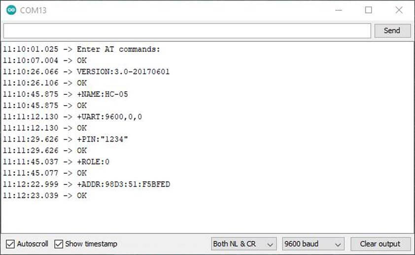
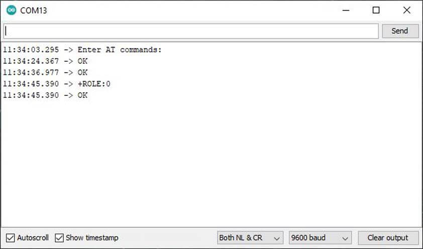
In the first image following I typed those commands :
- AT : The answer should be OK, it means that the module is in configuration mode and that it is "listening"
- AT+VERSION : Returns the version of the firmware installed
- AT+NAME : Returns the name of the module
- AT+UART : Returns the baud rate of the module
- AT+PSWD : Returns the PIN to connect to the module
- AT+ROLE : Returns 0 in default state. 0 : Student, 1 : Teacher (can connect itself to a student binded), 2 : Student "loop" (send the information back)
- AT+ADDR : Returns the address of the module
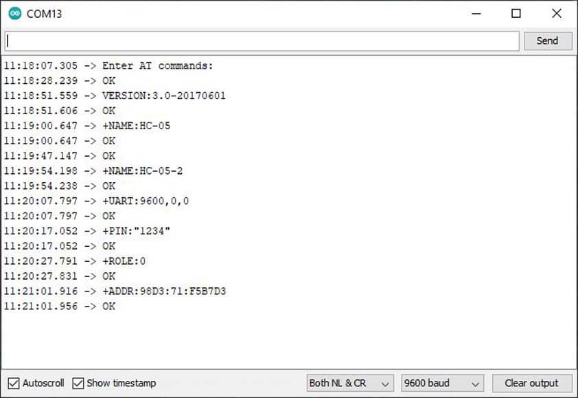
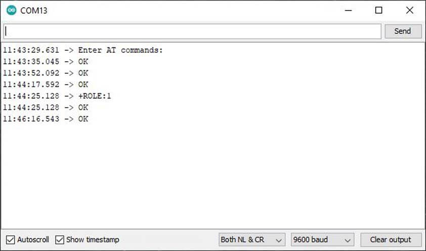
In the second image, I am configuring my second HC-05 module, here are the commands sent :
- AT
- AT+VERSION
- AT+NAME
- AT+NAME=HC-05-2 : To modify the name of the module
- AT+UART
- AT+PSWD
- AT+ROLE
- AT+ADDR
In the following images, I took the first module and decided it would be the Teacher one. In my first attempt, I simply typed the command "AT+BIND=98D3,71,F5B7D3" in the serial monitor, it returned "OK", but when I typed "AT+ROLE" to see if that valued was modified, it wasn't. Here is how to configure a HC-05 module into a Teacher role :
- Type "AT+ADDR" on the module that will be the Student to get its address, it should return something like that : "+ADDR:98D3:71:F5B7D3"
- In the serial monitor of the Teacher-to-be, type : "AT+ROLE=1" (1 is for Teacher mode)
- Type "AT+ROLE" to verify if the command was applied
- Type "AT+BIND=98D3,71,F5B7D3", it is the address of the student, we need to replace the ":" by "," when sending the command.
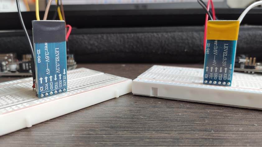
When the modules are connected we can see that the LEDs are blinking at the same pace.
To differentiate my modules I taped them, black tape is for Sensei, and yellow tape is for Yellow Belt.
▸ Arduino Code for HC-05 Teacher/STudent Communication
In the next image, I am using the second tutorial linked above, to make the modules communicate together. In the tutorial the person is able to open two serial monitors at the same time, it doesn't work for me so I am using the Arduino IDE on Windows, and on a virtual machine on Ubuntu. This way I can have the serial monitor for each module.
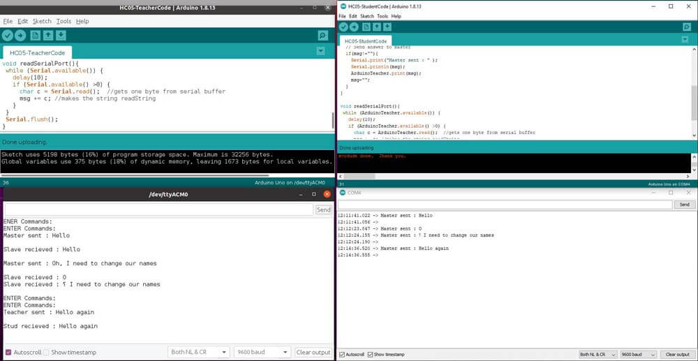
Here is the code for the Teacher module (I only modiied Master/Slave to Teacher/Student, the original source is linked here.) :
Here is the code for the Student module :
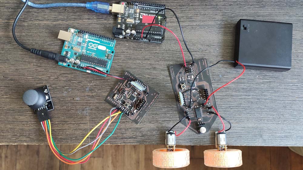
▸ DC motors remote control using HC-05 bluetooth modules
In the following part I used several tutorials, and this one mainly in order to use this connection between the module to control motors with a joystick.
There will be a controller board with a joystick and the HC-05 Teacher, and another board with a motor driver and the HC-05 Student.
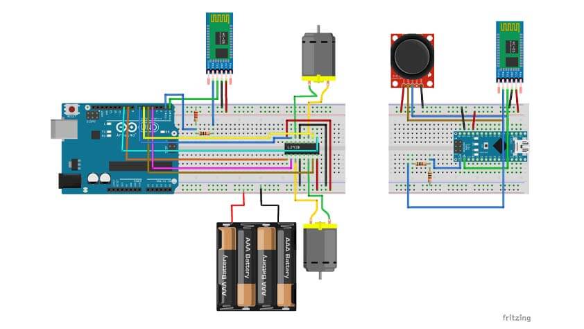
The Teacher board is composed of :
- 1 * HC05 bluetooth module configured as a Teacher at the address of the Student
- 1 * Joystick
- 1 * Arduino Nano
- 1 * 1K resistor
- 1 * 2K resistor
- USB for serial communication
- Breadboard and Jumper wires
The Student board is composed of :
- 1 * HC05 bluetooth module configured in default mode, binded to the Teacher
- 1 * L293D motor driver
- 1 * Arduino Uno
- 1 * 1K resistor
- 1 * 2K resistor
- 2 * DC motors
- USB for serial communication
- Breadboard and Jumper wires
▸ Arduino codes
These codes were provided on this great tuorial.
Here is the Arduino code used for the Teacher board : HC05-Joystick-Teacher-code.zip
Here is the Arduino code used for the Student board : HC05-Car-Stud-code.zip
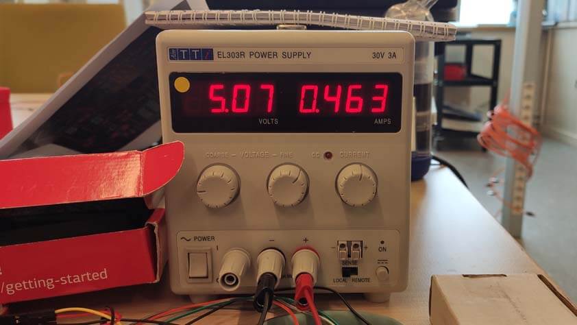
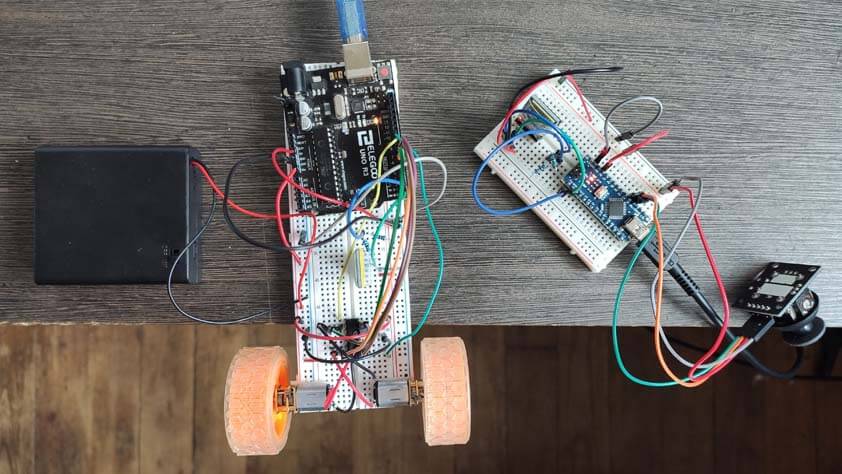
Here is a video of this set up in action, almost. Here the Teacher board is powered using USB, at 3V. The Student board has to power supply, the arduino is power supplying the bluetooth module, while a 6V alimentation is powering the motor driver. It needs more power but I can't provide more safely at home. But some good indicators are that, in one direction, it is clearly moving, and in the others, I can hear discrete motor noises. Communication seems to be happening.
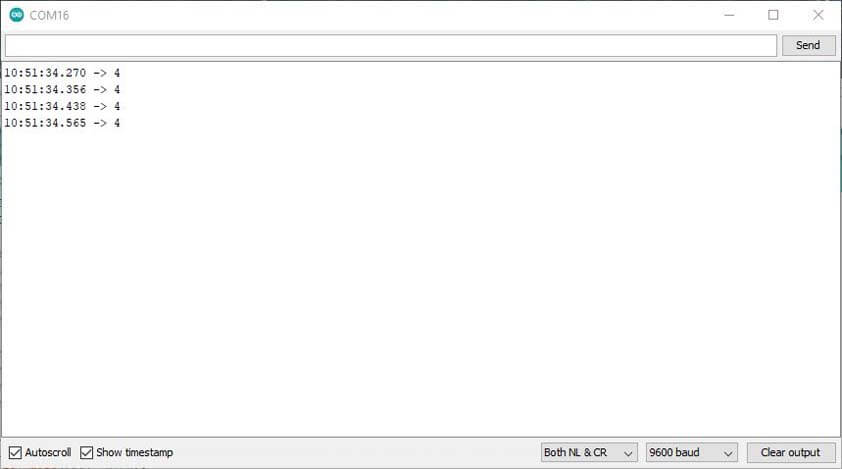
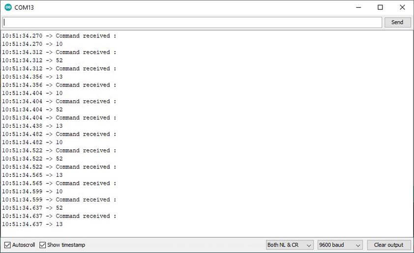
I used the serial monitors to visualize the communication between the modules, it appeared that they are talking, but the commands are lost in the translation. While the Teacher modules is sending the joystick position's values, the Student module prints not expected values.
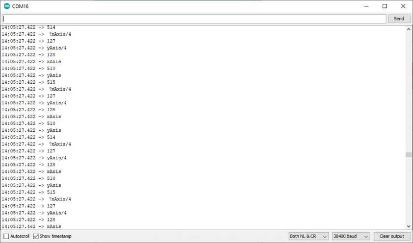
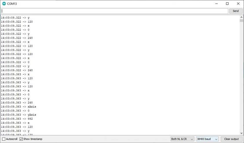
I tested several things in the code, what solved my issue was that even though I documented above that the baudrate for this module is 9600, the code I was using was set at a 38400 baudrate. The following images show that at the right baudrate communication is better, while the Teacher is sending the "Serial.println("4");, the receiver prints "10", "52", "13", which means "10 : New line", "52: 4", and "13: carriage return".
I used this ASCII table to translate these datas.
The next video shows that it is working better : the motors are moving in the expected direction, still, the motor board is under supply, and the result is not super reactive.
Here are the codes I wrote, using tutorial linked before, and my code from week 12, the Teacher code :
The Student code :
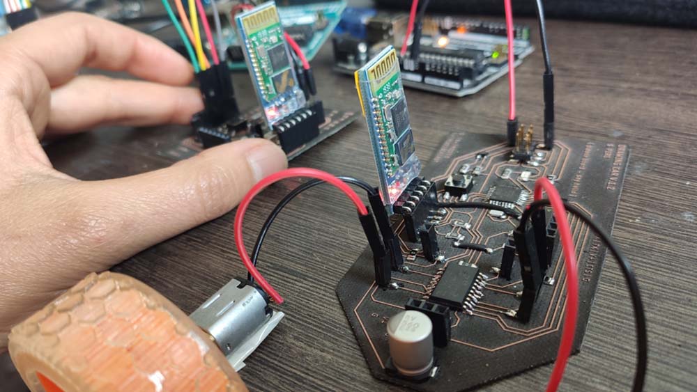
☛ Using my boards
This is an update published on june the 1st.
▸ Circuit Setup
Finally, I tested the programs with my boards. I am using an Arduino as an ISP, Arduinos to power the board, and batteries to power the L293D from the Drawing Car.
I used the HC-05 Bluetooth modules I used before, and it they connected together. Here are the codes I used they are similar to the ones displayed above, but I made modifications to light up the LED. Also, for now I can't controle the servo motor. I didn't find why yet. This part will be updated in the Final project.
Here is the video of the first test. As the pins were changed but not the code (when I filmed this, the code zipped above is modified to the right pins). It is working, but there is still a delay between the command sent and the command applied.