Week 8 : Embedded Programming
☛ Individual Assignment
☐ 1. Read a microcontroller data sheet, program your board to do something, with as many different programming languages and programming environments as possible
☛ Group Assignment
☐ 2. Compare the performance and development workflows for other architectures
☛ Taking the long way home
This week confirmed that I don't speak computer yet, but there's is progress indeed ! I tried something that didn't work properly (or so I thought) then I made my board dysfunctional by trying to resolve the issue I created in my non-speaking-computer-head - it became very hard to spot where the problem was so I restarted from scratch and it finally worked. Baby steps, but still steps.
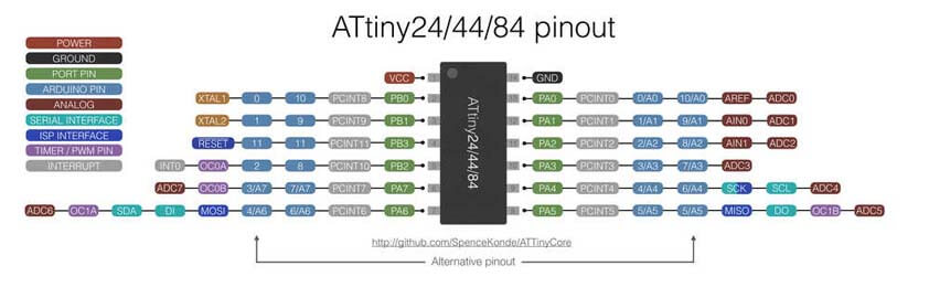
This image and the ATtiny44A Datasheet were real friends during this week, the datasheet provides the specifications of the microcontroller, what it can do and how to make it do it. To be honest, I don't think I understood everything from this datasheet, here is what I learned and an overview of the ATtiny44 pins.
The Atmel ATtiny24/44/84 is a low-power CMOS 8-bit microcontroller based on the AVR enhanced RISC architecture. By executing powerful instructions in a single clock cycle, the Atmel ATtiny24/44/84 achieves throughputs approaching 1MIPS per MHz allowing the system designer to optimize the power consumption.
The device is manufactured using Atmel´s high density non-volatile memory-technology. The on-chip ISP Flash allows the program memory to be re-programmed in-system through an SPI serial interface.
Pin configuration, from the Datasheet (page 60-65):
- Note :The numbers behind the letters are channels, for instance ADC0 or ADC2
- ADC0-ADC7: Analog Digital Converter
- AREF: External Analog Reference for ADC. In this case pull-up and output driver are disabled
- PCINT0-11: Pin Change Interrupt source 0-11
- AIN0: Analog Comparator Positive Input. Configure port pin as input.
- AIN1: Analog Comparator Negative Input.
- T0,T1: Timer/Counter source 0, 1
- USCK: Three-wire mode Universal Serial Interface Clock
- SCL: Two-wire mode Serial Clock for USI Two-wire mode.
- DO: Data Output
- SDA: Two-wire mode Serial Interface Data.
- DI: Data Input as USI Three-wire node does not override normal port functions pin has to be configured as input for DI functions.
- Miso: Master Data Input, Slave Data Output for SPI channel
- Mosi: Mater Data Output, Slave Data Input for SPI channel
- OC1B: Output Compare Match output. Can can be used as external output for Timer Counter1 MatchB. OC1B pin is also a output pin for PWM moder timer function.
- OC0B: Output Compare Match output. Can can be used as external output for Timer Counter0 Match B. Output pin for PWM mode timer function.
- OC1A: Output pin for PWM mode. Timer/Counter 1.
- OC0A: Output pin for PWM mode. Timer/Counter 0. Can serve as external output but has to be configured as output
- CKOUT: SystemClock Output, when CKOUT Fuse is programmed.
- CLK1: Clock Input from external clock.
- XTAL1, XTAL2: Chip Clock Oszillator pin1, pin2 used for chip clocks. When used as clock it can not be uses as I/O pin. When internal Oszillator is used, then pin can be used as an I/O pin.
- Reset: Ecternal Reset INput is active low and enabled by unprogramming "1" the RSTDISBL Fuse.
- dW: When debugWire Enable (DWEN) Fuse is programmed and Lock bits unprogrammed.
☛ Programming the ATtiny44A board using Ubuntu
I couldn't flash the Hello program on my board two weeks ago - time issues - so this is what I will begin with this week. During the Electronics production week I set up two environments to program my FabtinyISP, using the Arduino IDE, and using a virtual machine with Ubuntu installed on it and the AVR toolchain.
▸ Workflow
Here are the steps I went through :
- Modify the Blink sketch example on the Arduino IDE, so that the pins are corresponding to the ATtiny44 pins
- To obtain an HEX file from the sketch, go in the Arduino IDE toolbar, click on Sketch > Export compiled binary
- Open the terminal, cd to the right folder and type
avrdude -c usbtiny -p t44 -P usb -U flash:w:Blink44.hex
▸ Setup
During this test, Jonah lended me his FabtinyISP I plugged it to a usb cable to my computer, connected the ISP connector on both boards minding its orientation, and connected the VCC and GND pins from the FTDI header of my ATtiny44 board to a 5V alimentation.
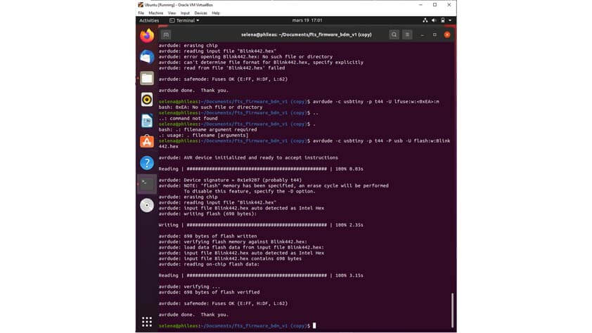
▸ Flashing the blinking program
To go through this step I opened the terminal in the folder were I have the makefile modified for the ATtiny44, and I ran this command avrdude -c usbtiny -p t44 -P usb -U flash:w:Blink44.hex - I don't have a video for this but I reproduced the same thing later and the video is later in the documentation. Well I ran this command and it worked, but the blinking cycle was very long. Longer than the 1 second cycle expected for the blinking.
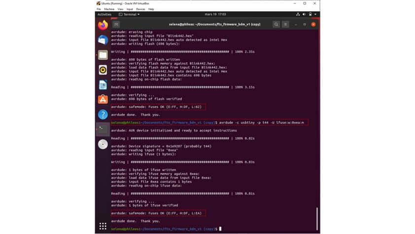
▸ Changing a fuse and making the board dysfunctional
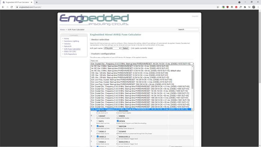
As the blinking was longer as expected I thought I just had to change the fuses - I read that the microchip has a 1MHz clock setted up by default so I went to this Fuse Calculator website, specified my chip and unclicked the "CKDIV8" which divide the clock by 8, and I ran this command in the terminal avrdude -c usbtiny -p t44 -P usb -U lfuse:w:0x6a:m to change the low fuse and get the "right" setup for my fuses.
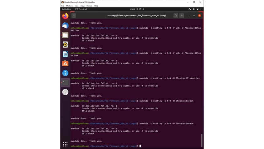
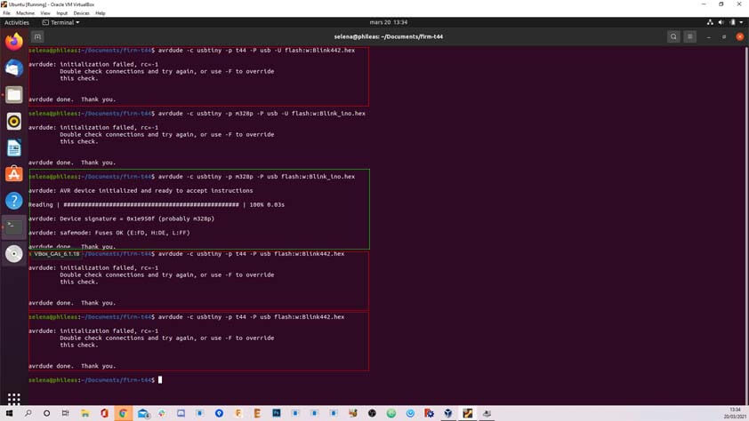
As soon as I changed this, I tried to flash the blinking program again but I kept receiving an error message : "avrdude : initialization failed rc=-1". I couldn't change back the fuse as the board wasn't recognized anymore - I tried to program another board to make sure the fabtinyISP was still working. Yes it was, in the image below the terminal shows that I tried to flash the ATtiny44 three times unsuccesfully, I also tried to flash an arduino uno board and it worked.
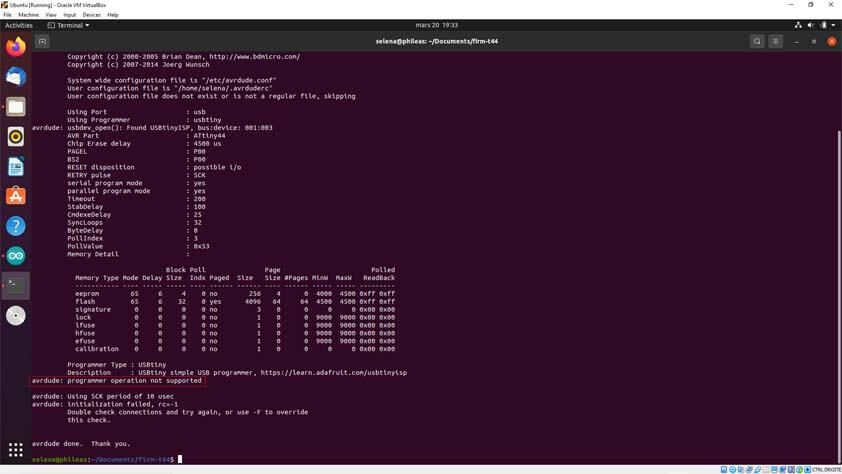
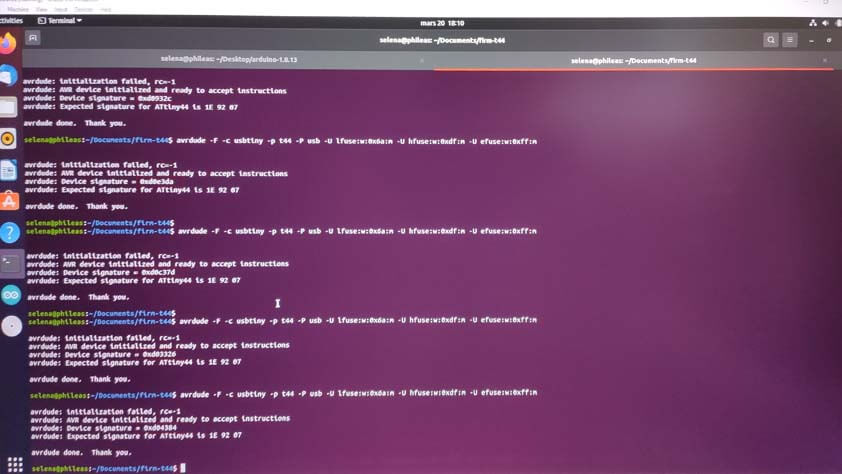
I ran again the command to flash the program by adding "-v" at the begining of it, in order to see the verbose. What came up is that I get a message saying "avrdude: programmer operation not supported". I tried to override the check by adding the "-F" flag, and it shows that the device signature is changing everytime I try to flash the board whereas the expected signature for the ATtiny44 is 0x1E9207.
▸ UPDATE : Changing a fuse and making the board dysfunctional
I made a test on the arduino IDE (a setup that had discovered the Electronics Production week) but it showed an error. The device signature was 0x00000000 and it is not changing in contrary to my previous try using Avrdude on Ubuntu.
Then I took a look at the fuse calculator website and I noticed something I should have noticed before changing the fuses - I didn't realise an external clock was selected by default on the Fuse Calculator website, so I changed my low fuse as if I had an external oscillator - whiwh is something it doesn't have. Therefore, my board is not responding because it is waiting for an external clock in order to be able to communicate.
☛ Remaking the board on a breadboard
As I was not able to fix the problem i created, I made my Hello board on a breadboard in order to try again without touching to the fuse part this time. The ATtiny board is not so tiny anymore.
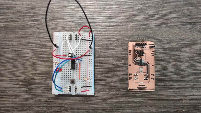
Here is my setup using the fabtinyISP to program the board, and using the Arduino board to provide current to my Hello board. I ran the flashing command but it kept on showing the "avrdude : initialization failed rc=-1" error message
☛ Programming the ATtiny44A board using the Arduino IDE
At this point I was advised by Adrian, during the Global Open Time, to use the Arduino as an ISP. These tutorials helped me for these steps : Fabacademy tutorial for programming ATtiny with the Arduino IDE and this one from Maximous on Istructables, to program an ATtiny44/45/84/85 with the Arduino IDE as well.
I had already tried to program with the Arduino IDE "on my own" but I missed an important step : in order to use the Arduino board as an ISP it is necessary to upload th ArduinoISP sketch (from the example sketches) in order to tell to the Arduino to act like a programmer.
▸ Workflow
Here are the steps I went through :
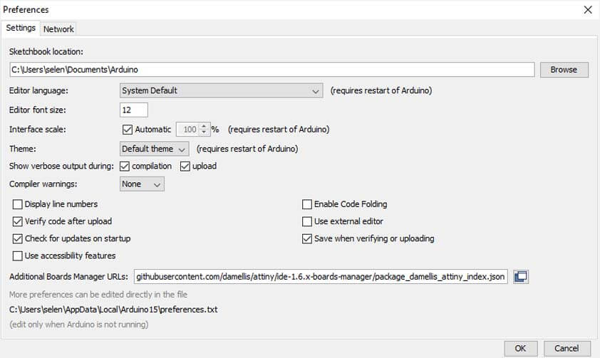
- Install the ATtiny board library from David A. Mellis - in the Arduino IDE toolbar go into File > Preferences and in "Additional Boards Manager URLs" copy the .json link to the board library.
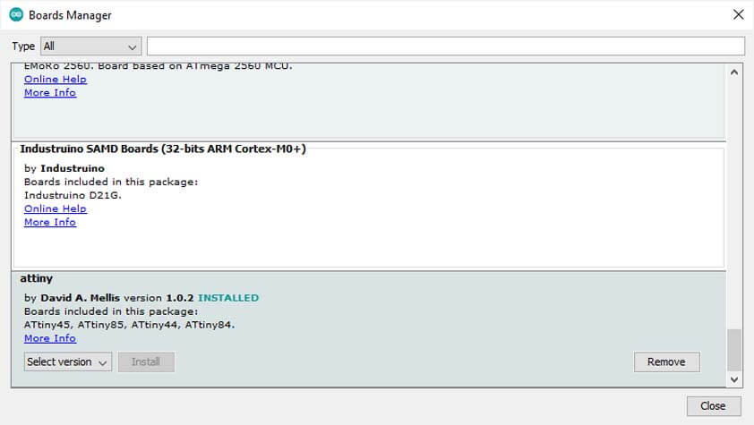
- In the toolbar, click Tools > Board Manager, and select the ATtiny library to install it
- Upload the ArduinoISP sketch to the Arduino in File > Examples > 11.ArduinoISP > ArduinoISP
- Modify the Blink sketch example on the Arduino IDE, so that the pins are corresponding to the ATtiny44 pins
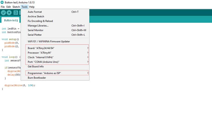
- In the Tools menu, it is important to select the chip you are going to program. You have to specify the Board, the Processor, the Clock, the Port (where the arduino is linked) and the Programmer : Arduino As ISP
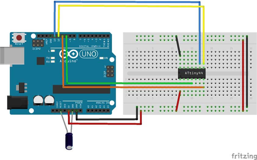
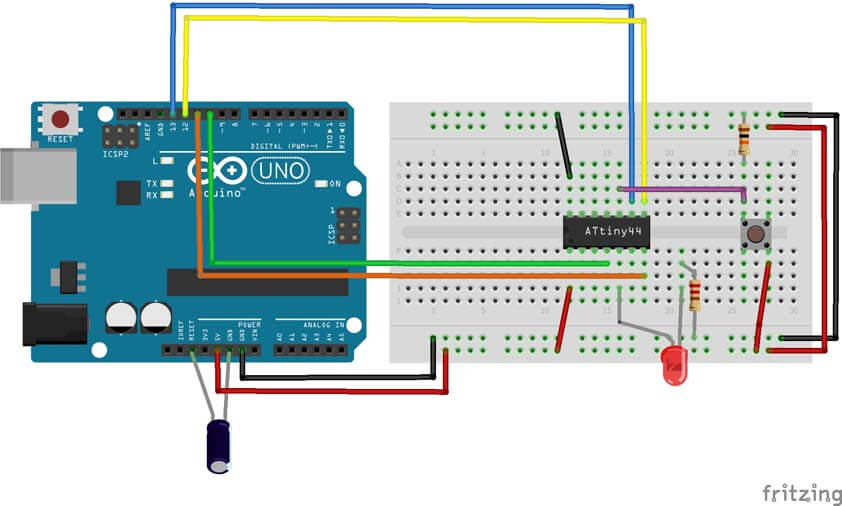
- Verify that the connections between the arduino and the Attiny44 are right, here is a schematic of the arduino as an ISP I made on Fritzing :
- When everything is checked and ok, you can compile the sketch.
- If it doesn't work, make sure you plugged the usb cable in your computer.
- If it still doesn't work, make sure you your tools are set up properly in the arduino ide. I think most of the errors I made are due to going too fast.
▸ Uploading the blinking program
I programmed the chip using the instructables tutorial, then I added a LED to the circuit to test it. I uploaded the Blinking program, and I expected it to work properly, but instead it was still a very slow blinking. This time I recorded it and I discovered that it lasts 8 seconds : 8 seconds on, 8 seconds off.
Here is the circuit for the following sketch :
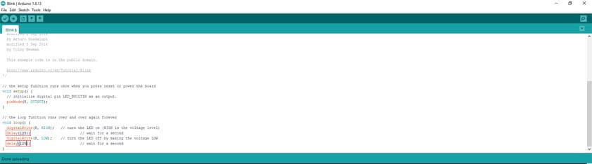
Here is the Blink example from Arduino, pins are modified to suit my board :
I modified the sketch and divided the delay by 8 to obtain a 1 second blinking cycle : delay(125);. I don't know how to explain this part. 8 seconds for 8MHz ? I should dig deeper to understand why it is acting like this.
I finally obtained a blinking program that I can control.
▸ Uploading the button program
I added a button to the circuit and I followed the same steps to upload this sketch, but it wouldn't work as expected at first : the LED was always switched on. My first plan was to check the sketch and the pins I was using, then to check the circuit, is everything connected the right way. Yes and yes. As it was not working with a regular switch button with 4 pins, I took an "interuptor" with 2 pins instead and it was working.
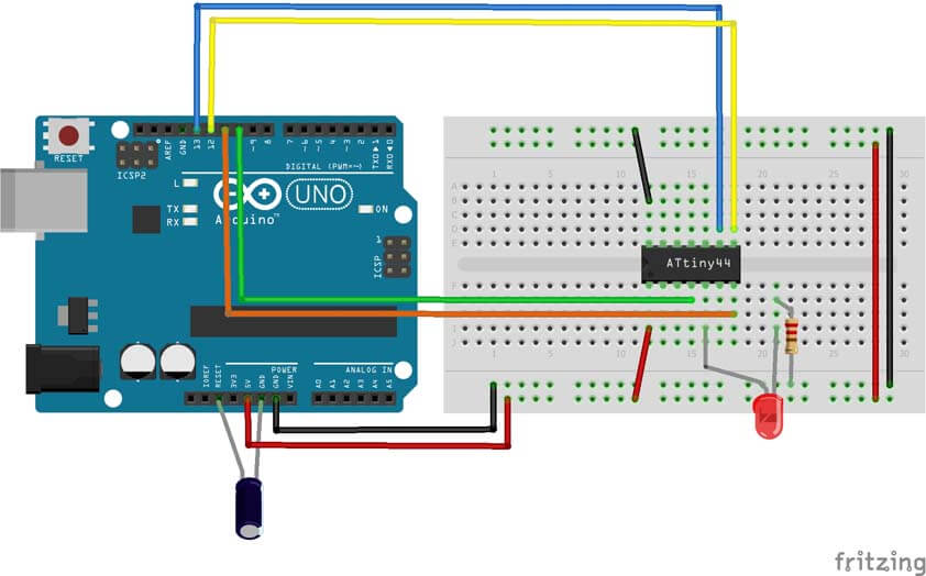
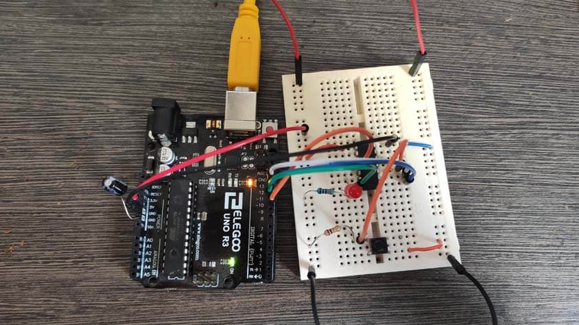
Here is the circuit for the following sketch :
Here is the sketch I wrote to switch on and off the LED using the button :
Changing this component made me realise that my circuit wasn't that right, I was creating a short in the button connection. I solved this and it finally worked.
Here is the video-proof :
▸ Blinking again
So far I was using the minimum amount of components to reduce the question marks in case it wasn't working. As it was working fine, I decided to swith to the Attiny44 breadboard. Here it is saying hello :
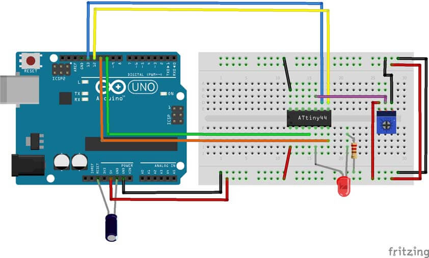
▸ Switching on the LED with a potentiometer
Here is a short sketch which allows to turn on the light by using a potentiometer. A potentiometer is a variable resistor, it has three pins, two are connected at the extremities of a fixed resistor, the middle pin divides the resistor by moving across of it when turning the knob, it gives the difference of voltage between the extremities. The sketch uses the pin PB3 from the microcontroller which is an analog one. The light turns on when the PB3 input detects that the defined threshold has been crossed.
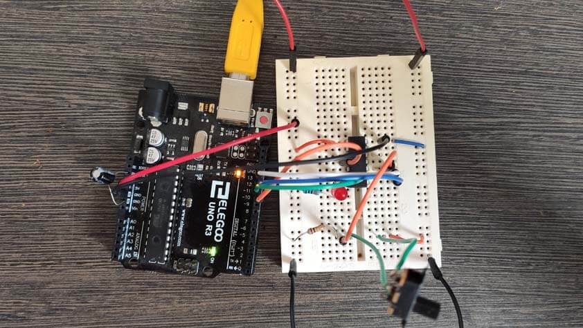
Here is the circuit for the following sketch :
Here is a short video of this set up in action :
▸ Modifying the LED luminosity with a potentiometer
This part was made with the help of this well explained tutorial. The sketch below allows to modify the LED luminosity by using a potentiometer. The potentiometer is plugged to VCC and GND, its third pin is connected to PA3 on the microcontroller, which is an ADC empowered pin ( an Analog to Digital Converter). In the sketch, we are reading an analog value, between 0 and 1023, then we map it to convert the value to a digital one, from 0 to 255. Then we say that the led luminance is proportional to the digital value, so it changes when we modify the value of the fixed resistor in the potentiometer.
Here is a short video of the LED turning on graduately as I turn the potentiometer's knob :
☛ "Blow the LED on" program
What I want to do next is to add a RC motor as an analog input, blowing on it creates a signal, I would like to use it to switch on the LED on my board.
It wasn't a single attempt. The motor I used for my first tests was always emitting signal when plugged in the circuit. It was creating a blinking effect - First I changed the threshold of my input, but even with a >500 threshold it was blinking and the LED was turning off when I was blowing on the propeller.
I switch to an Arduino and plugged the rc motor between tha A0 pin and the GND pin, then I used the serial.println in the Arduino code to display the value received by the arduino, it turned out that the rc motor was emitting values changing up to 556/1023. I decided to take another rc motor (lots of mini drones died here). The other motor I took was emitting 0 or 1 values when left alone, and up to 474 when I was blowing on it. I replaced the rc motor in the circuit and it worked as expected.
Here is the sketch I wrote to do so :
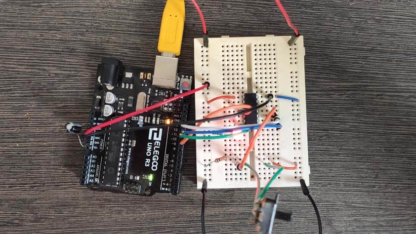
Here is the circuit for the following sketch :
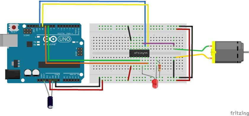
And here is the video of the LED turning on when I bolw on the motor :
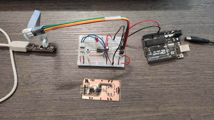
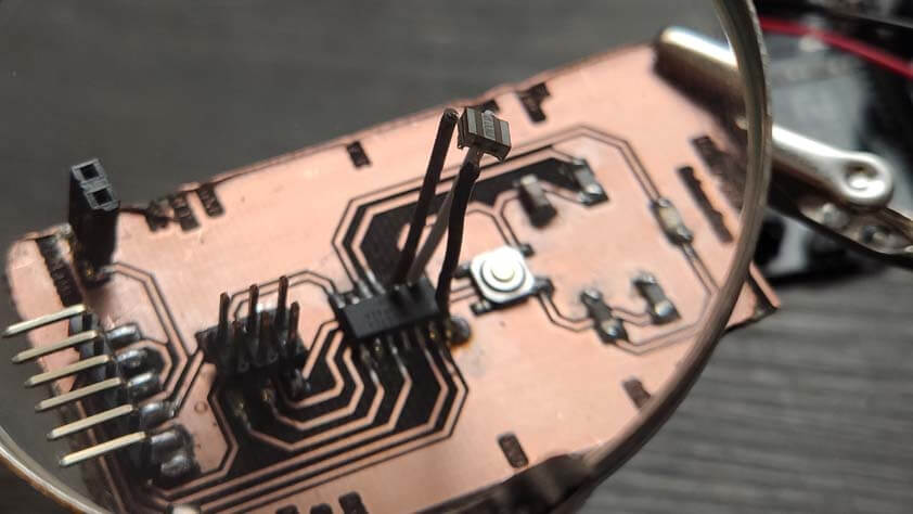
☛ Lets call it the Crystal Quest
In the previous episode, I decided I didn't have to read carefully every line and options in that Fuse Calculator website, and I didn't notice the default setup of the clock. It led me to set my low fuse for an ATtiny44 with an External 8MHz clock, therefore it was not possible to flash anything on it as it was waiting for a crystal. Jonah gave me that 8MHz crystal and I soldered it on my board with jumpers. Like so :
Next, I tried to flash a program with the Arduino setup I have been using so far. A good sign was that the board started blinking as soon as I plugged it to the arduino. The next video is the Attiny44 board and its 8Mhz crystal blinking :
Then I plugged a RC motor in the headers on my board and flashed the program to turn on a LED by blowing on the propeller, here is my hello board finally working as I expected - I had to mute the video as I didn't how to mute them when the page is loaded, but you can see the propeller turning and the LED turns on, as it stops turning, the LED turns off :
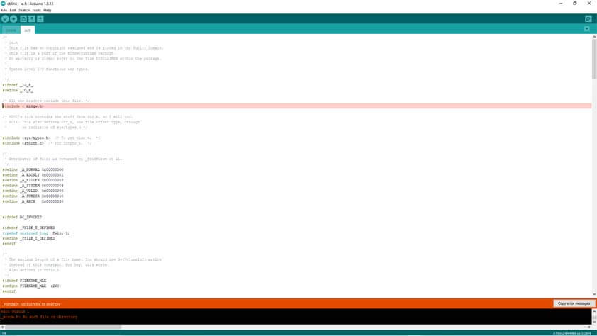
☛ Programming in C
Jonah wrote a C code to blink a LED and shared it to me so I can see how it works at least. I tried on my computer with the arduino IDE but I couldn't find the libraries required to run it from the Arduino IDE.
Here is a screenshot from Atmel Studio, when the code is wrote we can program it on the board flash memory.
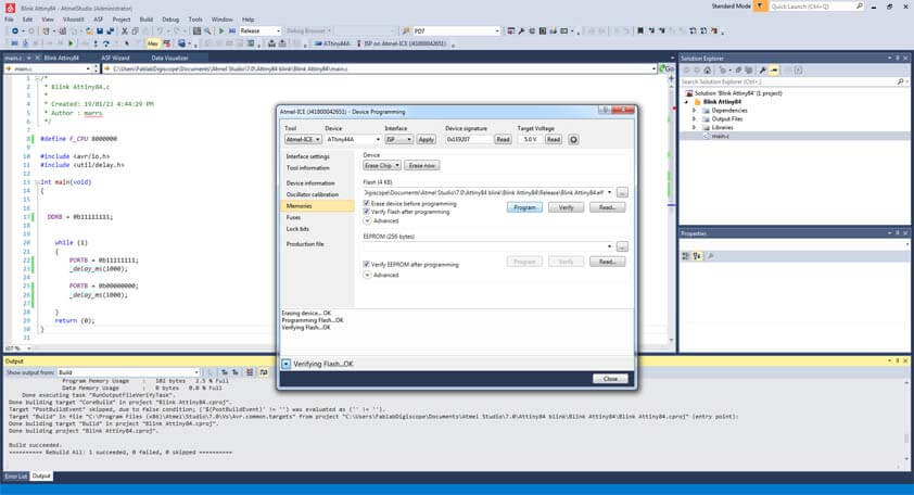
Here is my board blinking thanks to a C code. Well I will have to do it by myself later !