Week 9 : Mechanical Design, Machine Design
☛ Group Assignment
☐ 1. design a machine that includes mechanism + actuation+automation
☐ 2. build the mechanical parts and operate it manually
☐ 3. document the group project and your individual contribution
☛ Choosing the machine
This week with Ambroise and Quentin we had to choose a machine to built, regarding our desires and the components available at the fablab. We chose to make a Pick and Place machine, by beginning by the XY plotter which is the base of its working concept.
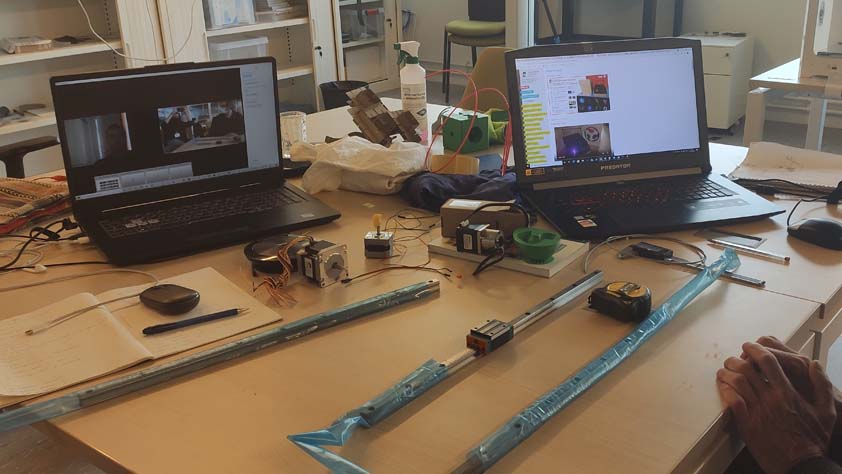
We began the week at distance so we had to share what were the components available, discuss which one we will use and how to manage the group work.
☛ 3D model of the machine-to-be
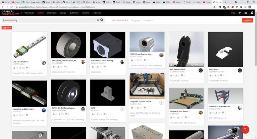
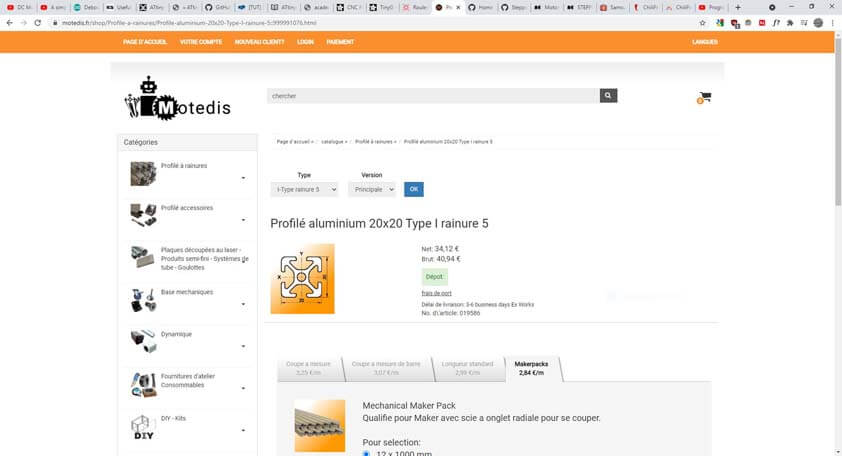
The next step was to modelize the components we had to produce a structure for the machine out of it. Some vendors website make available the 3D model for their parts, it takes some time to gather it all, but once it is done we can be more confident about the 3D model we want to design.
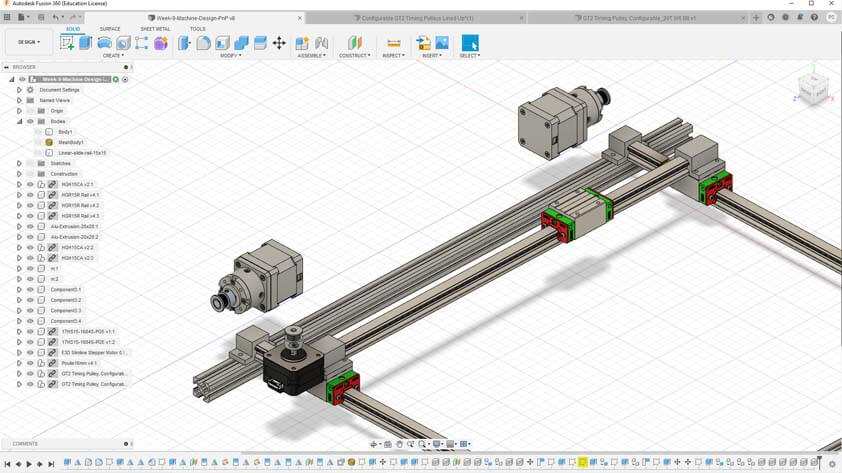
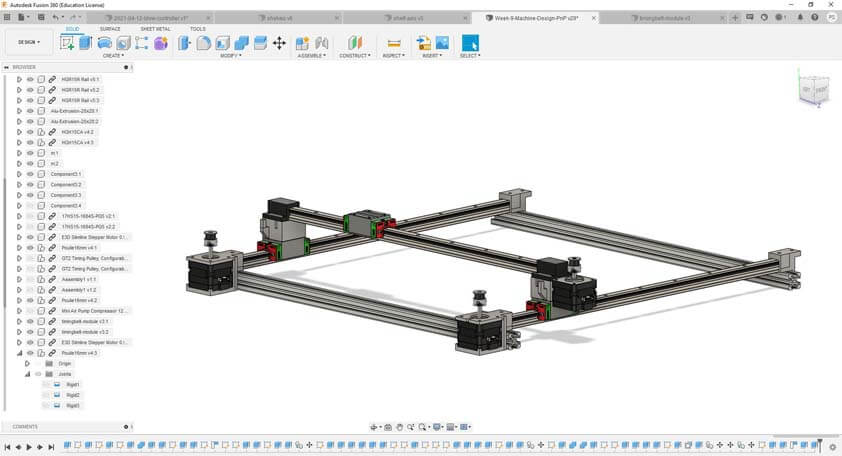
The images below shows my fusion file with all the components gathered or designed, and the global structure for the machine. A great thing in Fusion 360 is that it is really easy to add external parts to our design, they're linked to the main file and need to be refreshed if they were modified. We couldn't use it this way yet, but Fusion 360 seems to be a useful collaborative tool.
☛ Designing a module for the timing belt and motors for Y axis
Ambroise and Quentin made the structure for the X axis, sor our head module was softly moving. After discussing it with them I designed parts to transmit motion from the motor through the timing-belt in order to move the X axis.
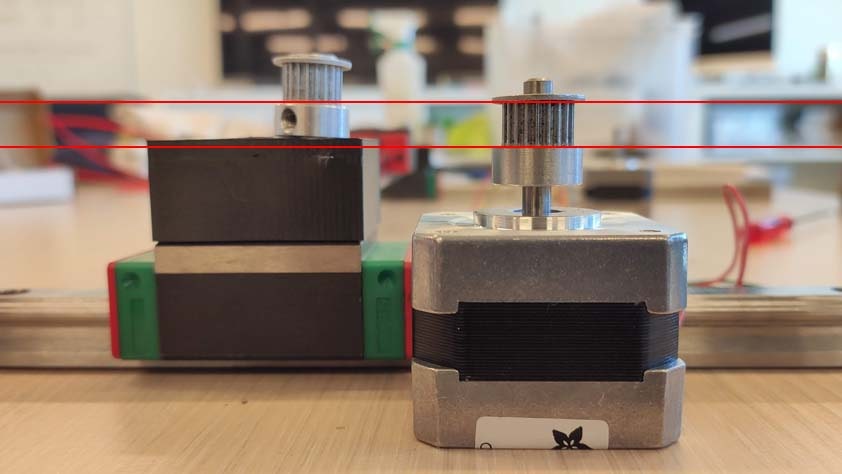
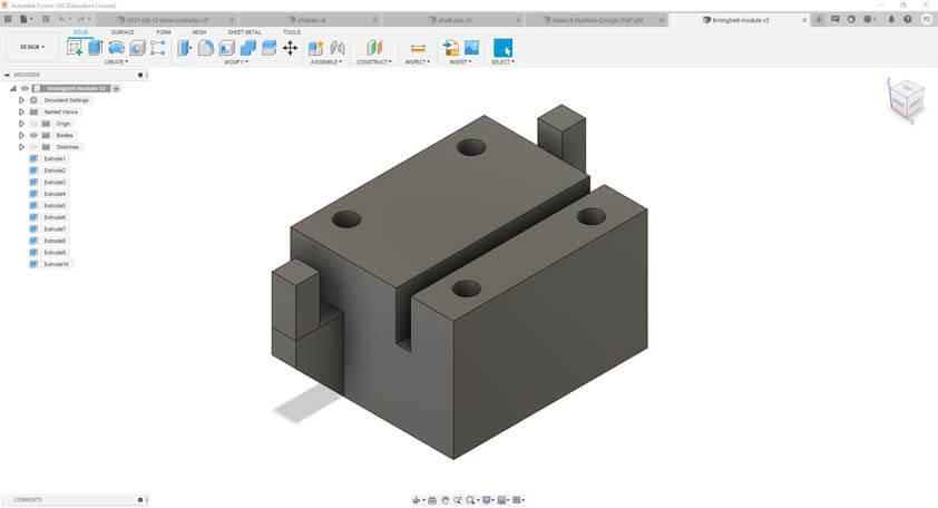
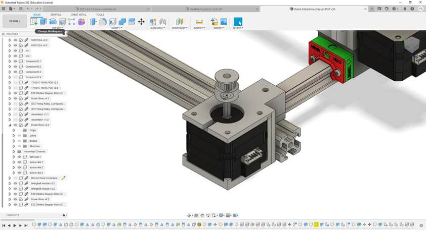
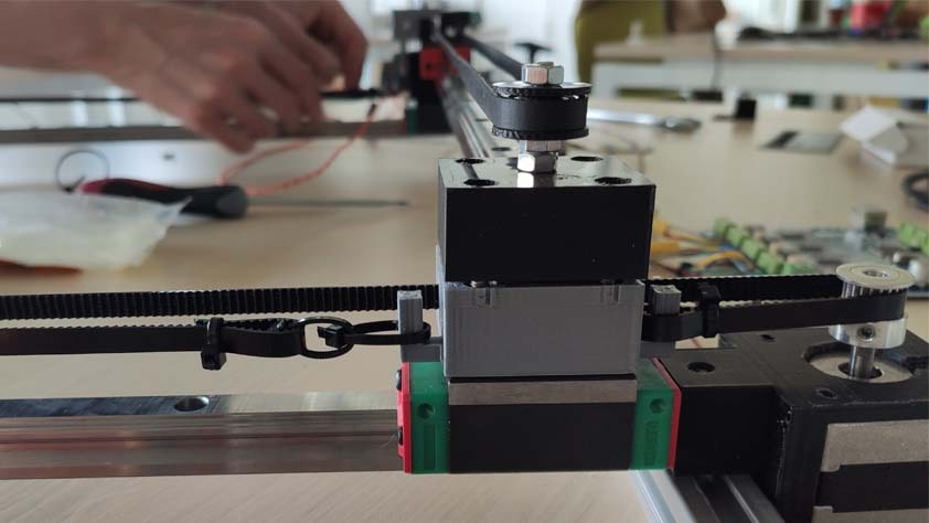
The images above shows the motor we are using and at which level (approximatively) the timing-belt could be passing, then the raw part to make it. The two images below show the motor holder, in which the motor is clipped for more stability, and the pulley holder. Both parts are fixed into the extrusions of the frame.
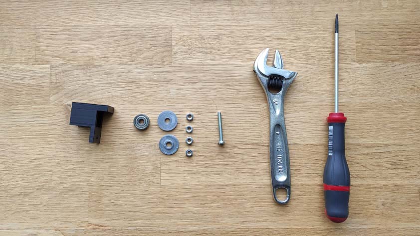
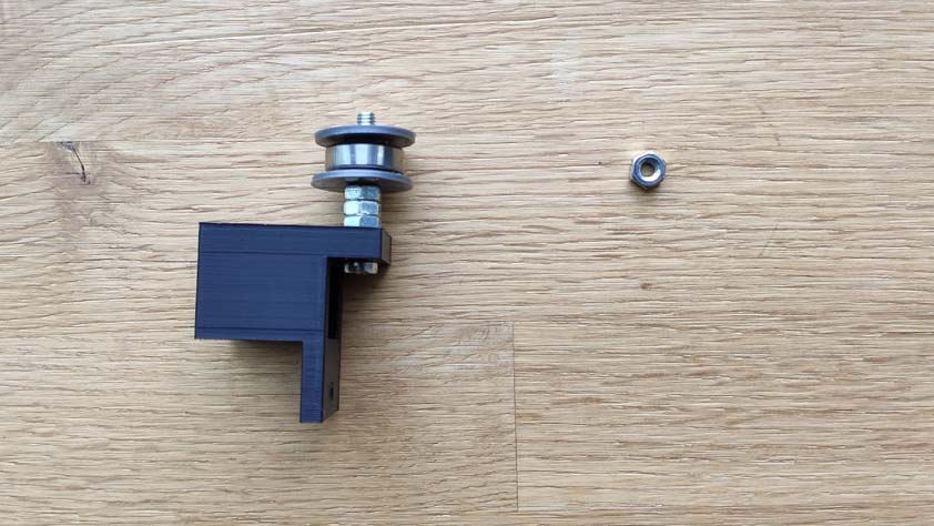
☛ Assembly for the pulley system
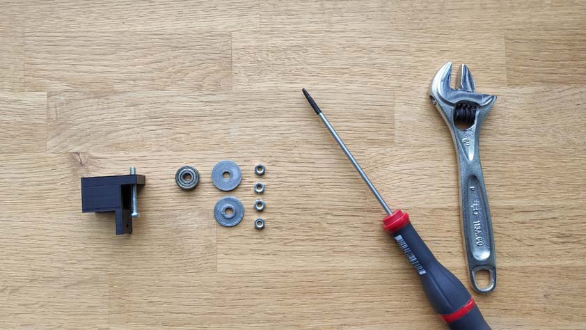
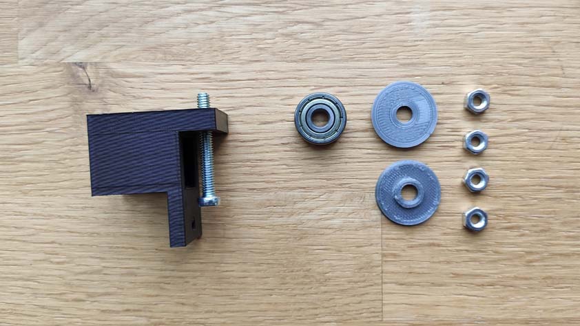
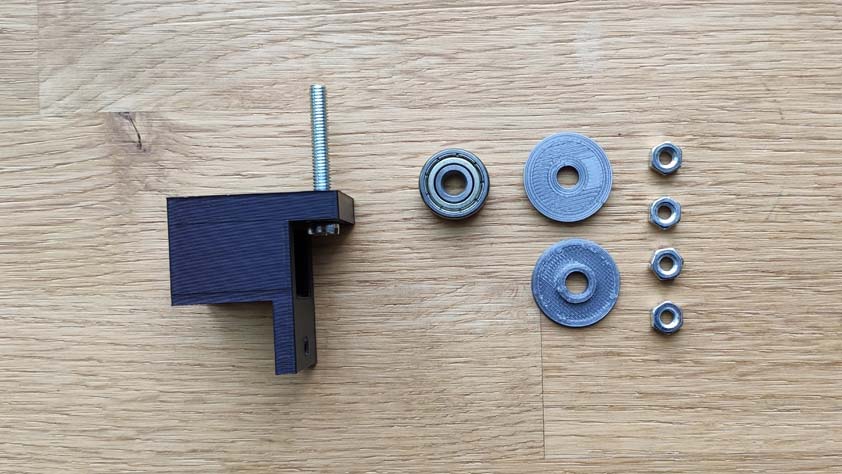
The pulley system Ambroise imagined is very cool and simple to set up. He printed "sliced rings" as we didn't have those, in order to trap the timing belt around the ball bearing. Here is the process pictured :
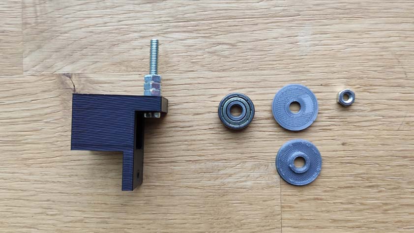
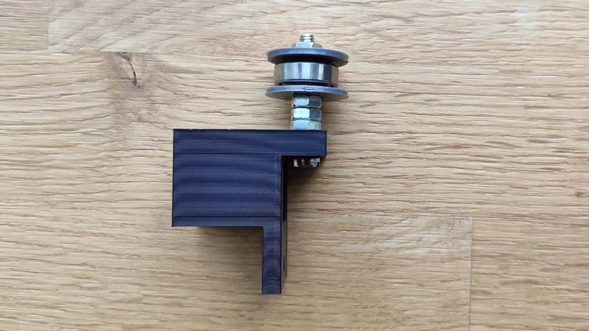
And here is the final result, efficient and simple.
Assembly of the parts to the machine :
The pulley holder :
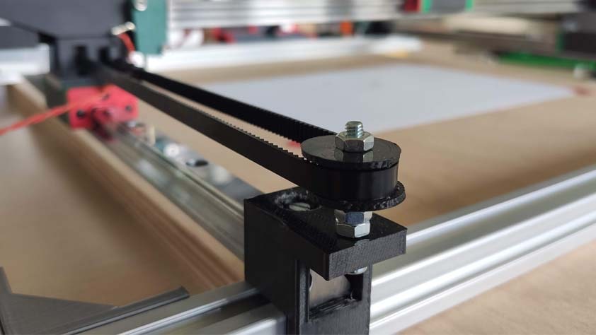
Both axis :
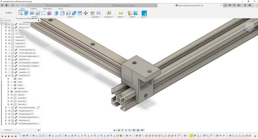
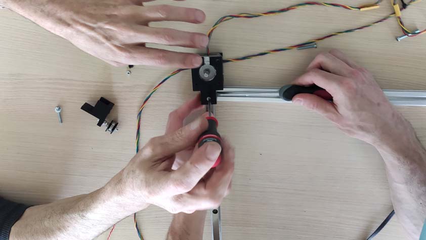
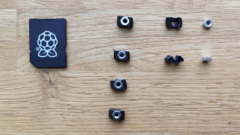
A very useful tip when working with the standard 20x20mm extrusion, you can actually 3D the parts to hold a screw in it :
☛ Overview of the machine
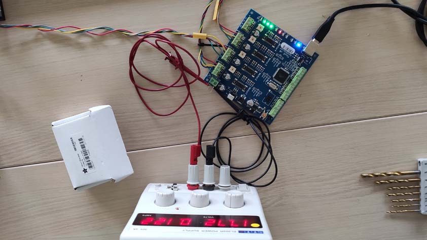
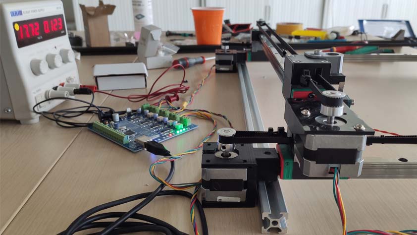
Quentin used the TinyG and chiliPeppr to communicate with our setup, here is the tinyG power-sourced.
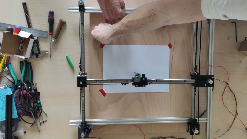
Here are pictures of the whole machine.
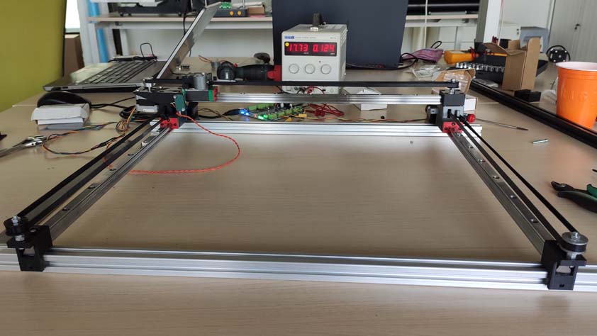
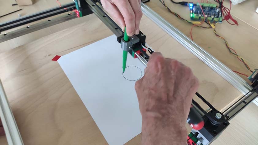
Then we tried to send gcode to it in order to make it draw something with the module Quentin designed. The second image shows the first circle !