In this page, I’m required to document all the steps I did to build my final project. I didn’t have a clear path on how I should start with it or what should I write first so I opened the dashboard and started following the instructions and answered some of the questions.
1. What does it do?
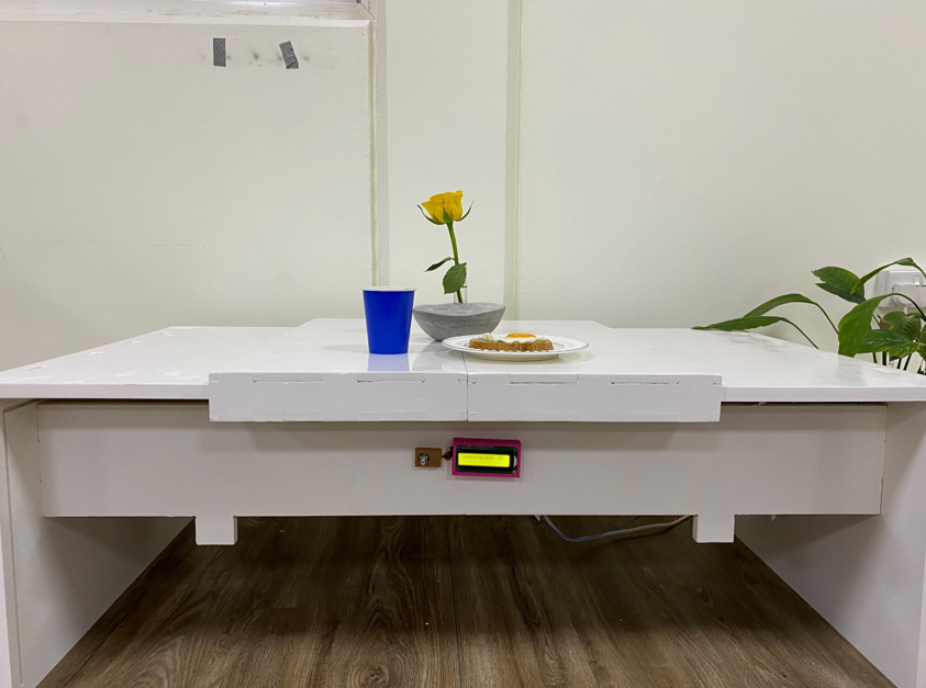
The table contains a heating pad that is attached to the aluminum which heats the food once the power source is connected and turned on. To control the heating pad temperature, I used a potentiometer. I used L2C screen as well to display the reading of the temperature which helped me decide if the current temperature is appropriate or not.
2. Who’s done what beforehand?
There is a Japanese invention called Kotatsu which is a low wooden table frame covered by a futon (heavy blanket) upon which the table sits on. Below the table is a heat source, previously it was a charcoal brazier but now a days it has been replaced with a electric source. However, my idea is different than this where the table itself will be used to heat the food.
3. What did you design?
4. What materials and components were used? Where did they come from? How much did they cost?
| Component Name | Quantity | Link | Cost |
|---|---|---|---|
| Electric Heating Pad | 1 | link | 124 AED |
| Solid State Relay | 1 | link | 38.99 AED |
| Teflon | 1 | available in the lab | 20 AED |
| Plywood 18 mm | 1 | available in the lab | 300 AED |
| PLA filament | 1 | available in the lab | 30 AED |
| AC power cable | 1 | available in the lab | 10 AED |
| Aluminum | 1 | available in the lab | 130 AED |
| atmega328 | 1 | available in the lab | 15 AED |
| Resistor 499 ohm | 1 | available in the lab | 0.073 AED |
| Crystal Resonator | 1 | available in the lab | 0.40 AED |
| AVRISP | 1 | available in the lab | 0.50 AED |
| Resistor 10k ohm | 2 | available in the lab | 0.46 AED |
| Headers (1x3) | 5 | available in the lab | 1.25 AED |
| Resistor 0 ohm | 2 | available in the lab | 1.25 AED |
| Capacitor 22 PF | 2 | available in the lab | 0.05 AED |
| MOSFET N-CH 50V 16A TO-252AA | 1 | available in the lab | 0.58 AED |
Total cost = 672.56 AED
5. What parts and systems were made?
6. What processes were used?
For the table 3D design I used Fusion 360 and I used the laser cutter machine to test my design then I used the ShopBot CNC machine to cut the required parts to make the table.
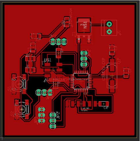
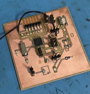
For the circuit board I used Eagle software for designing and the Roland CNC milling machine for the milling process. As for the soldering process I used the soldering kit.
For the potentiometer & screen cover I used Fusion 360 to design the 3D parts then I printed them using Ultimaker 3D printer
7. What questions were answered?
8. What worked? What didn’t?
9. How was it evaluated?
It was evaluated based on its ability to heat the food to a desirable temperature.
10. What are the implications?
At the beginning I thought the project will benefit me only since I have a hobby of taking pictures of my meals. However, after implementing my idea I shared it with a couple of my friends and they thought that this idea is really useful and they want a similar table since it will help keep their food warm & hot when they’re taking pictures of it or having a long chat with their friends & families. So I can say that this idea might be life changing when it comes to these aspects.
Let me start by talking about the electronics part of my project.
Electronics
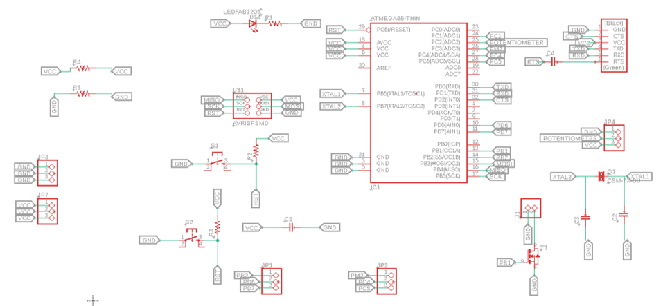
I used one circuit board for my final project which is atmega328 . It’s very similar to the Arduino Uno board. All the details can be found on my Input Device week. As for the L2C screen details its available in my output devices week
I had to search on the internet on which pins should I add to my board to able to connect the potentiometer, I2C LCD, SSR and NTC sensor. below is the list of what I added on my board.
To connect the LCD with my board I added Analog Pin 4 & Analog Pin 5, GND and VCC.
To connect the SSR with my board I added a Analog Pin, GND & VCC
To connect the SSR with my board I added a digital pin and GND.
To connect the NTC sensor with my board I added a Analog pin, GND, VCC and resistor.
Table Design
I made my 3D design using Fusion360. VCarve Software to be able to get the g-code format for the CNC ShopBot. All the details requiring the table design & fabrication processes can be found in computer controlled machining week.
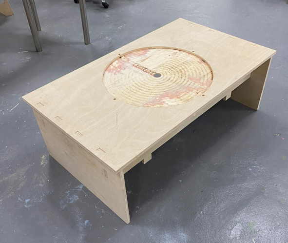
Aluminum
400mmx400mm. Based on these dimensions I drew a circle on the VCarve with a diameter of 570mm then I cut it using the ShopBot machine.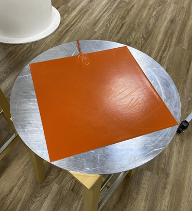
Sliding Pieces Design
I designed two sliding pieces that were exactly the same. One will be placed on the right side of the table while the other will be placed on the left side. When I need to open the heater I’ll move them to the side and turn on the heater and close them back to cover the heater.
Fusion360 for the 3D design. The design is demonstrated below. I made 4 small rectangles for the sliding piece. It was designed this way so that it fits the table in an exact way.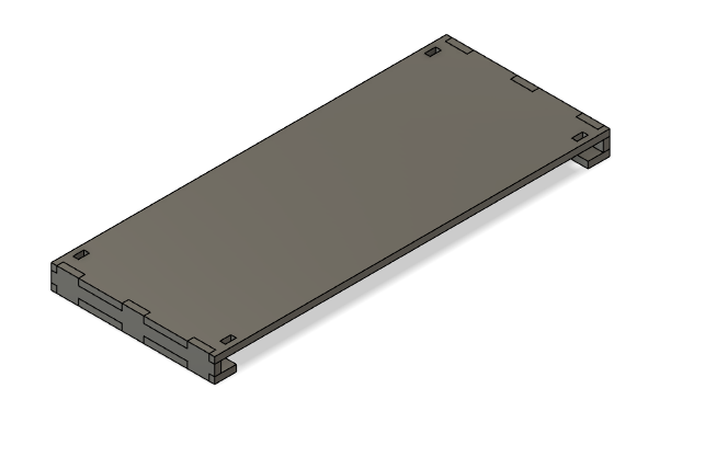
ShopBot machine & for the painting part the Fablab driver Armin attached the pieces for me & painted the table along with the sliding pieces.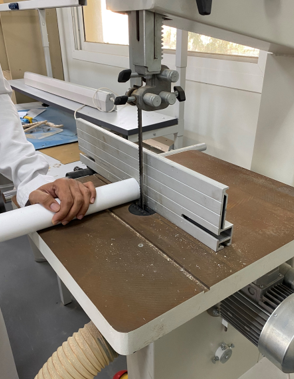
I fixed the Teflon on the wooden sheet using a double sided tube.
I drew a half circle on VCarve & followed the same steps that are mentioned on the computer controlled machining week. to cut the Teflon using ShopBot.
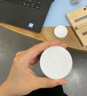
Potentiometer Cover
Fusion360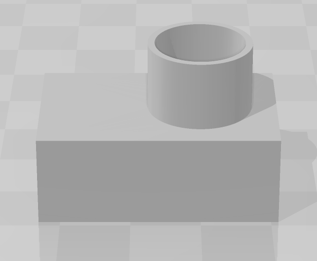
Ultimaker.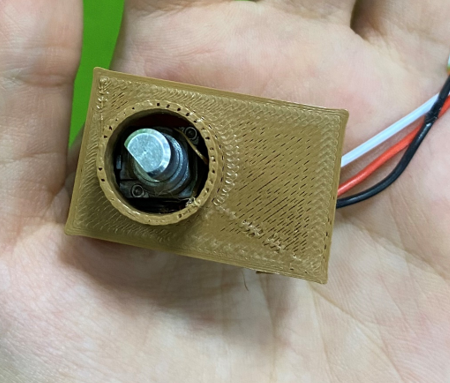
I’m not satistfied with the result but due to the lack of time this is what I come up with.
I2c screen Cover
Fusion360.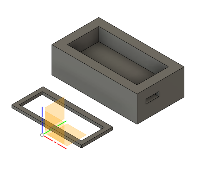
Ultimaker.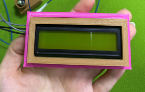
I’m going to list down the helpful tutorials that helped me to write the final project code.
I used NTC sensor for my project. its already attached to the heat pad. so with the help of this tutorial I was able to program the heater.
with the help of this tutorial I was able to know how to connect the SSR to the power source. In my project the Relay worked as a switch it turn the heater on and off. The below video shows the test I did for the relay and the NTC sensor.
with the help of this tutorial I was able to program the potentiometer. The potentiometer test can be found in the input devices week.
with the help of this tutorial I was able to program the I2c LCD. The LCD test can be found in the output devices week
As I mentioned before I used atmega328 board for my final project. the code I used is shown below:
#include <Wire.h>
#include <LiquidCrystal_I2C.h>
int ThermistorPin = 3;
int Vo;
float R1 = 10000;
float logR2, R2, T;
float c1 = 1.009249522e-03, c2 = 2.378405444e-04, c3 = 2.019202697e-07;
int heater = 10;           // the PWM pin the heater is attached to

void setup() {
   pinMode(heater, OUTPUT);
Serial.begin(9600);
}
void loop() {
   int sensorValue = analogRead(A2);
  // print out the value you read:
  Serial.println(sensorValue);
  delay(1);
digitalWrite(heater,HIGH);
  Vo = analogRead(ThermistorPin);
  R2 = R1 * (1023.0 / (float)Vo - 1.0);
  logR2 = log(R2);
  T = (1.0 / (c1 + c2*logR2 + c3*logR2*logR2*logR2));
  T = T - 273.15;
  T = ( T - 32.0 )/1.8;
   lcd.print("Temperature: ");
   lcd.print(T);
  lcd.print(" C");
  delay(500);
}The below video shows how the table work.
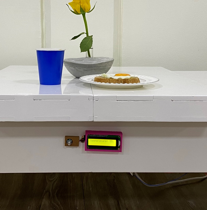
The below picture shows the table interface.
when I zoom in it's shows in the screen that the temperature of the heater is now 55 C
The final project presentation and video can be found on my Invention, Intellectual property, and Income week
The main challenge that I faced was during the final projects presentation period since it was my first week at work & I barely had time to organize stuff. I wasn’t able to go to the lab except after my work is done so it placed some hard constraints on me & the time was short so I couldn’t accomplish things as I used to previously. Not to mention that I barely had time for myself due to the time constraint but thankfully I was able to finish my final project and present it although the time wasn’t on my side. The second major issue I faced was the programming part & dealing with wires and electronics since I had zero to basic knowledge only so I had some issues when I get an error code since I didn’t how to deal with it & how to trace it. Thankfully I was able to deal with this issue as well with the help of Eng. Hashim & my colleagues. The third issue I faced is when I connected all the wires to my circuit board, the screen and the potentiometer didn’t work but I didn’t have time to know the root cause of this error so I did the project without these parts.
Although I’m happy of what I achieved with this project, there’s always an area of improvement since nothing is perfect from the first time. Later on in the future I’ll add a button that controls when the heating source is turned on/off rather than being turned on immediately when I turn the electricity from the power source. I would also like to add an insulating part the prevent the table from burning which will make the table safe to use. Lastly, I want to make the sliding pieces move automatically rather than by moving it manually by adding a motor to it.
I would like to start by thanking Hamdan Bin Rashid Al Maktoum foundation for providing me with this opportunity. I want to thank Fablab UAE as well for guiding us through this entire journey by providing all the necessary tools that will help us get the most out of this program during this unexpected pandemic which helped me learn, develop a lot of new skills. I would like to reach my thanks to our instructor Hashim for his support throughout this course. Finally, I’d like to thank all my colleagues & FabLab driver Armin for his help.
