In this week we are required to add one or more sensor to our microcontroller board that we designed and read it. I am going to use the potentiometer for this week as it will be part of my final project.
The link if the group assignment can be found here
An input device is a piece of hardware used to provide data to a computer used for interaction and control. It allows input of raw data to the computer for processing.
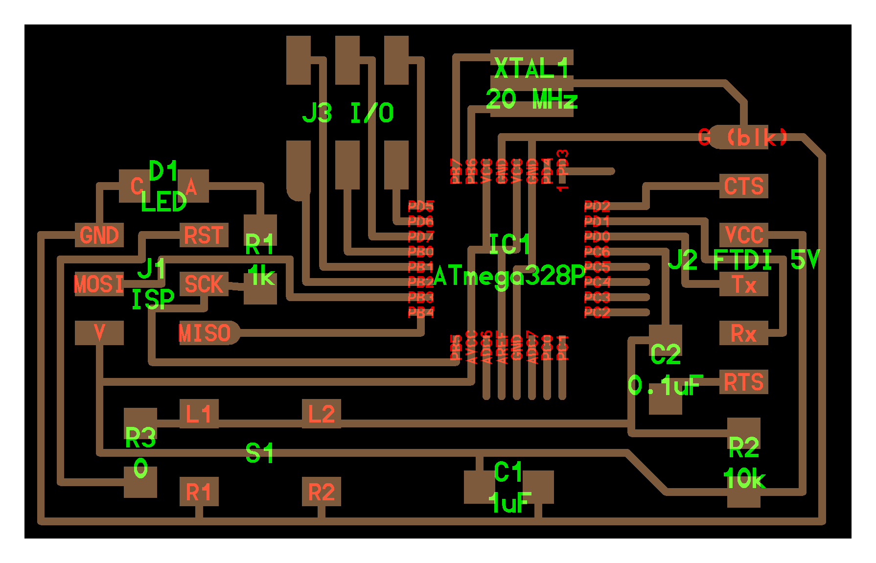
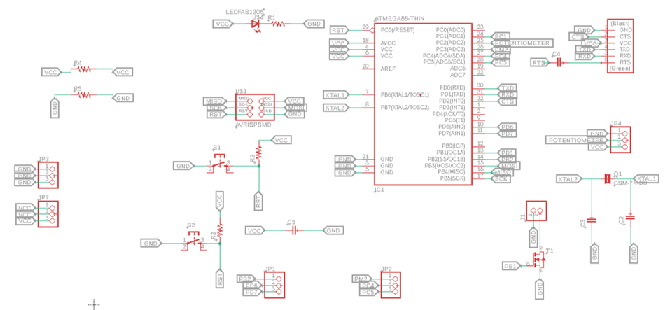
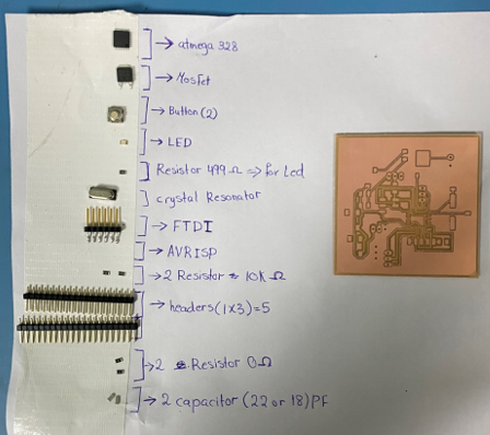
I will use atmega328 which is similar to Arduino Uno board but the difference between them is that The Arduino is a complete system (Hardware with supporting components), and software. The atmega 328 is a Microprocessor that needs external components, and a programmer to operate. I’m going the explain the steps that I did in order to design the atmega328:
atmega328
Resistor 499 ohm
Crystal Resonator
FTDI
AVRISP
2 Resistor 10k ohm
Headers (1x3) = 5
2 Resistor 0 ohm
2 Capacitor 22 PF
MOSFET
I had to search on the internet on which pins should I add to my final project board to able to connect the potentiometer, I2C LCD, SSR and NTC sensor. below is the list of what I added on my board.
To connect the LCD with my board I added Analog Pin 4 & Analog Pin 5, GND and VCC.
To connect the SSR with my board I added a Analog Pin, GND & VCC
To connect the SSR with my board I added a digital pin and GND.
To connect the NTC sensor with my board I added a Analog pin, GND, VCC and resistor.
Then instead of using fabmodulus or Mods our instructor explain for us a new software which is easier and take less time and effort than fabmodulus. This software called flatCAM.
To move the file to flatCAM I clicked on Manufacturing tool >> CAM to open the cam processor, generate and export the Gerber files.
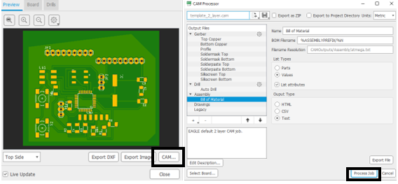
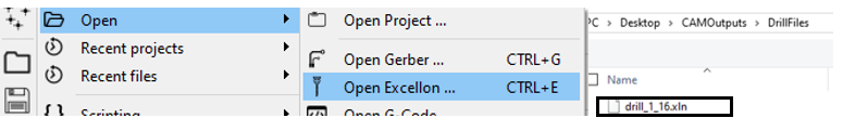
flatCAM and open the Gerber files ( the traces and the outline ) and the Excellon files (for the drill parts) as shown below: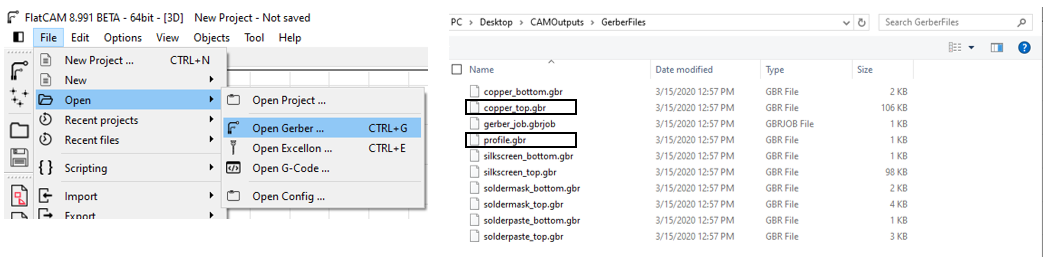
Then I opened my colleague Maha page and follow the same steps.
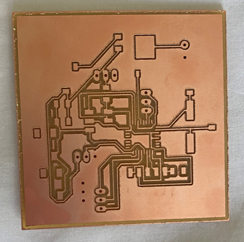
I used the Roland SRM-20 CNC machine for milling the board, but modified the setup in the software to accommodate the file extension I am using.
for the milling process I repeated the same steps that I did during the electronic production week
Soldering
 .
.
 .
.
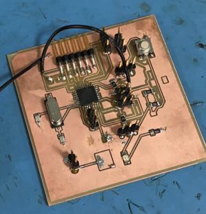
There was a problem in my design. I didn’t connect the RST pin on the FTDI to the RST pin on the AVRISP so I had to add a wire to connect the two points.
When I tried to program the board with FTDI I keep getting an error and I couldn’t find the error so I asked for help from my instructor and he couldn’t solve the problem so he advised me to use the ISP to program my board instead of using FTDI. and on the ISP can’t open the serial monitor to check the values so I used Arduino Uno to check my code and the potentiometer if its work or not.
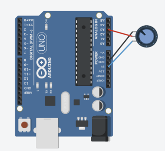
As I mentioned in the above paragraph I wasn’t able to use the serial monitor with my board so I used Arduino Uno. I connected the potentiometer to the Arduino Uno as shown in the below picture.
 .
.
There are three terminals. the first one is connected to the Ground (GND). The second one is connected to the Analog Pin(3). The last one is connected to the VCC Pin (5V).
// the setup routine runs once when you press reset:
void setup() {
  // initialize serial communication at 9600 bits per second:
  Serial.begin(9600);
}

// the loop routine runs over and over again forever:
void loop() {
  // read the input on analog pin 3:
  int sensorValue = analogRead(A3);
  // print out the value you read:
  Serial.println(sensorValue);
  delay(1000);        // delay in between reads for stability
}I’m going to use the potentiometer to change the temperature of the heater on my final project.