At the start of this week we were required to produce an ISP chip by using the CNC milling machine, solder the components as required and finally we were required to program the ISP. To start things off, I want to note out that I did not have any background regarding this area so I was dealing with this thing for the first time in my life, and when I tried to solder the components I failed several times until I was finally able to do it correctly. But hey! I won’t say that I didn’t have fun doing so, the experience by itself was so entertaining and I felt that every time I was making progress, the most difficult part was to program the ISP chip since I didn’t attend the lecture that week due to the weather conditions on that day so I was a bit late and I didn’t know where to start but thankfully my colleagues helped me and I was able to finish programming the chip. If there is anything that I want to recommend, You should not skip a lecture because the work you will have to put in will be twice or three times the effort needed if you attended the lecture itself
Here is the Link of the group Assignment page
I opened this tutorial and implemented the following steps:
The traces PNG files and the board outline has to be downloaded.
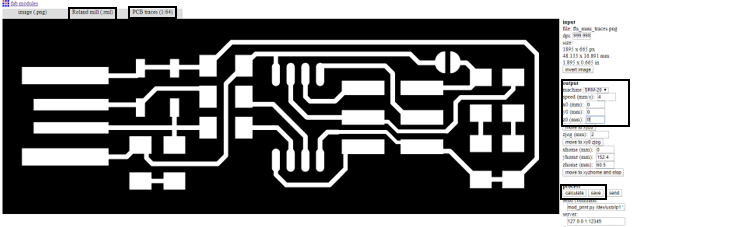
Open the [Fab Modules]((http://fabmodules.org/) and then insert the image -> Output (Roland Mill) -> Process -> PCB traces (1/64) -> Machine (SRM20).
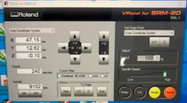
Now you should change the settings of the XYZ axis to Zero as shown in the figure below.
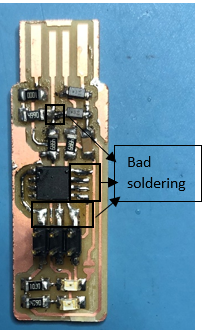
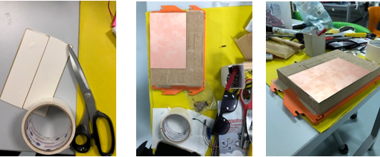
After we’re done, We moved to the computer that is connected with the machine to start the milling process
Now we should fix the “FR1” plate on the MDF by using a double sided tape.
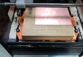
We have to fix the milling bit inside the machine.
Now we have to control the directions of the XYZ-axis coordinates which can be done by using VPanel software.
After setting the XYZ coordinates, We have to ensure that the XY-axis coordinates aren’t touched where as the Z-axis should be changed depending to ensure that the milling bit touches the MDF.
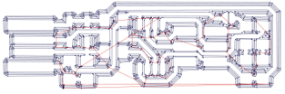
Now go to cut -> Delete all -> Add traces -> Output.
The same steps will be repeated for the board outline, but we have to change the milling bit to (1/32) this time.
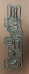
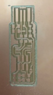
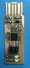
Now the circuit board is ready and is shown in the figure below.
The newest FABMODULES is called MODS. TheMODSis more capable than the previous modules and works by connecting the nodes to develop each process. The workflows within the MODS can be customized as one wishes by loading several modules at one time or by using a precompiled program.
I used the MODS to perform the CNC milling machine test, by inserting the PNG picture for the line test and performed the necessary changes and then saved the stl file in order to use it in the CNC milling machine. But whenever I start up the process the milling bit lifts up into the air which causes the machine to start the milling process in the air. I tried the same process on 3 separate occasions but I keep ending up with the same issue so I decided to use the FABMODULES to do the line test for the CNC milling machine.
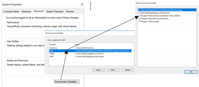
Go to system properties -> Environment variable -> Path -> Add the bath as described in the tutorial.
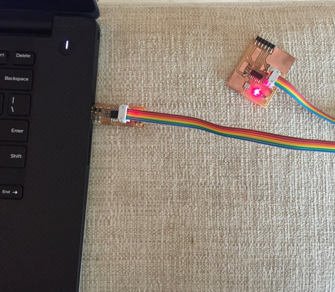
I connected Engineer Hashim’s FabISP (Programmed ISP) with my ISP and then installed the Zadig driver and clicked install.
Now I have to download the firmware and extract the files.
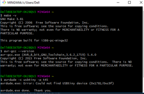
Open the git bash on the firmware folder and write down the following commands:
make flash The following command erases the target chip, and it will program the flash memory with the contents of the.hex file that was previously built.
make fuses The following command will set up all the fuses excluding the fuse that will disable the reset pin.
make rstdisbl The following command works in a way that is very similar to the make fuses command, but this command includes an extra feature which is thhe reset disable feature.
There were several problems that I faced while working this week.