I was assigned to :
Read the microcontroller data sheet.
Programmed the circuit board that was previously built by using several programming languages.
I programmed the circuit board to do the following features:
To turn the LED ON/OFF in a certain amount of time.
To turn the LED on after pressing the button and it automatically switch off if the button wasn’t interacted with.
The link if the group assignment can be found here
First of all we have to read the microcontroller data sheet which basically contains a plethora that contains the detailed information of the data. By the help of my instructors, I was able to simplify what was required from me and how to tackle things right from the beginning, So my main focus was trying to understand the most important things that will serve as a base for me where I can improve it down the road. Now I’m going to note down what are the most important things that I learned this week.
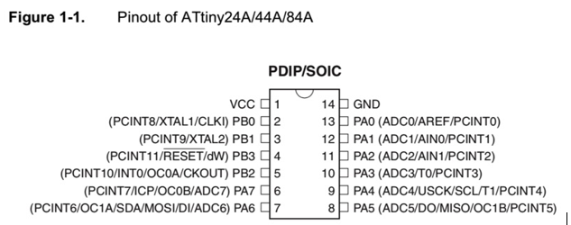
The following figure represents the pin configuration of the ATTINY44 microcontroller that I used in my circuit board and below I will list down it’s configurations.
VCC pin: Supply Voltage
GND pin: Ground
Port A (PA0 to PA7): 8bit (00000001) I/O port with internal pull-up resistors.
Port B (PB0 to PB3): 4bit (001) I/O port with internal pull-up resistors.
// Shamma Fab Academy 2020
//the button is connected to pin 10
// LED connected to pin 5 which is Number 8 in Arduino
void setup() {
  // put your setup code here, to run once:
  pinMode (8,OUTPUT);
}
void loop() {
  // put your main code here, to run repeatedly:

    digitalWrite (8,HIGH);
    delay (500);
    digitalWrite (8,LOW);
    delay (500); }
As you can notice in the previous coding, the LED is connected to pin 8 (PA5=analog pin). So after uploading the code, the LED will turn ON where the digital write will be high and after a delay of 500 it will automatically turn OFF and the cycle will repeat itself after every 500 consecutive delays and the condition will be changed from ON to OFF and vice versa. However if I increased the delay to a number greater than a 500, It will take longer time to switch the LED from ON to OFF.
I felt familiar with programming language since we took a dedicated programming course that mainly focused on the C++ programming language so this part was easy for le and I really enjoyed using this program, I will list now a summary of what I learned regarding the microcontroller and bit manipulation by using the C language to generate the required code.
Port B in ATTINY44 has 4 bits which means 0001
Port A in ATTINY44 has 8 bits which means 00000001
8 bits is equivalent to 1 byte
The AVR microcontrollers are designed in order to allow the dual-use of its pins, which is actually an advantage since it allows the developers to use the pins as I/O pins if the function they are used for is not necessary or is not being used. Moreover, the AVR microcontroller pins and not strictly fixed as inputs or outputs during the manufacturing stage, But instead these pins can be configured by the use of a software.
The atmel AVR is a 8 bit microcontroller and all its ports are 8 bit wide. Every individual port contains 3 registers that are associated to it each containing 8 bits. Every individual bit contained within those registers serve a purpose on configuring the pins of a certain port. Bit0 (registers) is associated to Pin0 (port) while Bit1 is associated to Pin1 and so on.
There are three I/O registers that are associated DDRx, PORTx and PINx. Each having there unique functions while the x refers to the GPIO port name (A,B,C,D).
1.DDRx - Data Direction Register
This register stores the configuration information for the PORTx pins. If you write 0 in the pin location of DDRx will make the physical pin of the port an input pin, whereas writing 1 will make it an output pin. For example if you want to make all the pins of port A as input pins you should use the following code (DDRA=0b000000000;) and if you want to make all the pins of port A as output pins you should use the following code (DDRA=0b11111111;)
2.PORTx - Pin Output Register
This register stores the logic values that are showing as outputs on the physical pins of the PORTx if the pins were originally configured as output pins. If you want to write a value to a port you should write the values directly to the PORTx register of that specific port.
3.PINx - Pin Input Register
This register stores the current state and the logic value of the physical pins that are displayed on PORTx. In order to read the data from the port pin, you have to change the port’s data direction to input at the beginning before attempting to read it. This can be simply done by setting the bits ro zero values in the DDRx. If the port was set to output, the PINx register will show data that has been output on the port pins.
There are 2 main input modes. You can use the activate internal pull up or use port pins as tri-stated inputs. The example below explains how to correctly read data from port A.
DDRA=0x00; (Set port A as an input)
x=PINA; (Read the contents of port A)
Below is a C language code for my circuit board:
#include <avr/io.h>

int main (void)
{


DDRB |= (1 << PB2); // set PB2 as an output which is LED

DDRA &= ~(1 << PA3); // set PA3 as an input which is the button


PORTA |= (1 << PA3); // Activate pull-up resistor at PA3


    // Insert code

    while(1) {

       if (PINA &(1<<PA3))  // if button pressed
        {
            PORTB &= ~(1<<PB2); // set PB2 high = switch on LED
        }

        else
        {
            PORTB |= (1 << PB2); // set PB2 high = switch off LED
        }
    }
    ;

    return 0;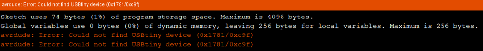
}This week I faced many issues, The first being when I run the code I keep getting an error.
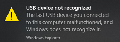
The second issue was that my ISP was not being recognized by my laptop, So I told myself that the issue was from my ISP but I asked my colleague Maha to give me her ISP to see if the issue originally was from my ISP but I found that the error was from the laptop itself and my ISP was fine.
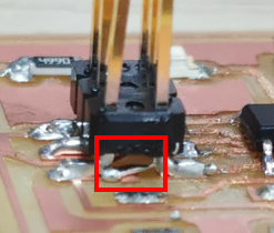
I used Maha’s laptop to program my circuit board and then I used my code but I faced another issue, which was when I programmed my circuit board in a way when I press the button the light turns on but what happened was the light remained on the all the time so I thought that there was a short circuit, So I got a multimeter and checked but there wasn’t any short circuit, but when Eng. Hashim checked he found that there was a short circuit and it is labelled in the figure below.
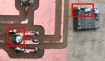
So I removed the short circuit and re-did the soldering process once more and then I reprogrammed the circuit but I ended up with the same issue but this time the short circuit wasn’t detectable by the naked eyes so I didn’t know that there was a short circuit but Eng. Hashim was able to detect it so I removed it again and I did the soldering another time and I double checked all the connections to ensure that there will be no short circuits but the same issue kept occurring! The light remains on and till now I wasn’t able to find a solution to this issue regardless of all the efforts that I dedicated towards it.