In this week we are required to make something big. I was so exited for this week because I took a course about manufacturing during my bachelors degree but due to the time we weren’t able to make any furniture on the lab so now in the Fabacademy I have a chance to do what ever I wasn’t able to do it during university. Firstly I was planning to make a floor shelf, I got this idea when I was browsing painterset website and I notice a shelf made by recycling wood that utilize iron connection. So, I asked myself what if I can do it fully by wood without using any screws. The first step was sketching the design then convert it to digital copy by using Fusion 360. But Again due to covid-19 and the lack of time I changed my plan and decided to make my final project design instead which is a tray table.
The link if the group assignment can be found here
Document how I design the object
Document how I made the CAD-toolpath
Document how I made something big (setting up the machine, using fixings, testing joints, adjusting feeds and speed, depth of cuts, etc..)
Describe the problems that I faced and how I fixed them
Fusion 360 for the 3D design
VCarve Software to be able to get the g-code format for the CNC ShopBot
Universal Laser Machine (PSL6MW) to test the design if its fit or not using the cardboard and mdf
ShopBot
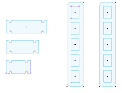
As I mentioned in the introduction I made a floor shelf design and I tested it using the cardboard and mdf. I am going to show my attempts to make the design fit.
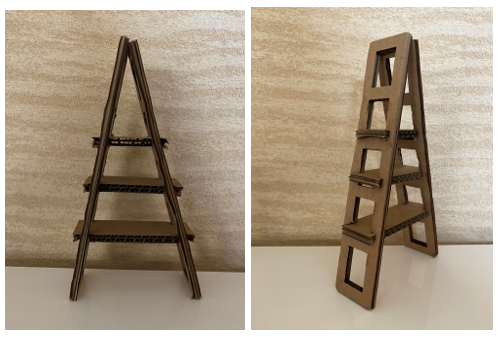
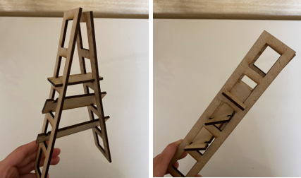
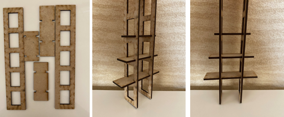
The design was not good I don’t really like it. I was not satisfied with it. so I was planning to make some modification to the design but as I said due to the lack of time I changed my plan and decide to make the tray table design for my final project.
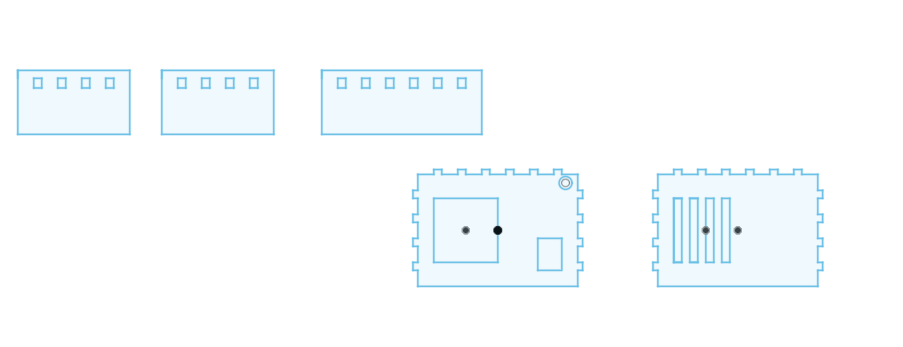
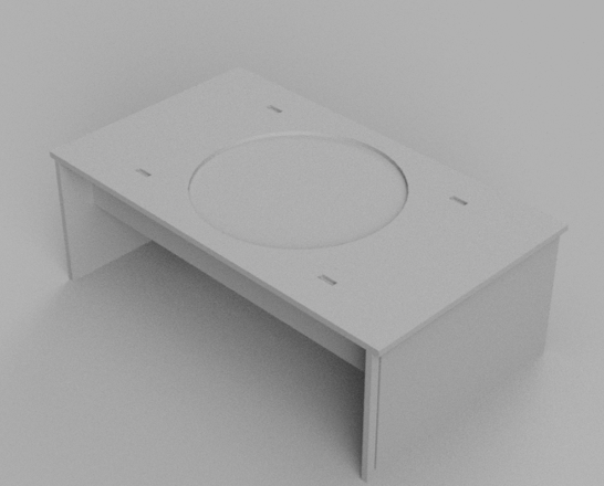
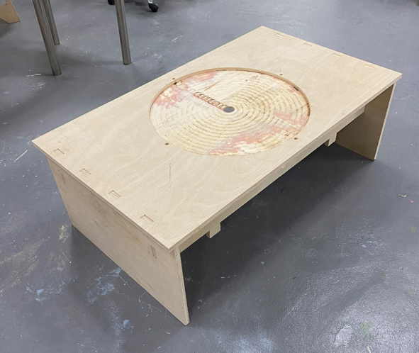
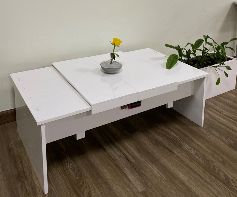
The second design that I made is my final project design (tray table). I made the 2D design using Fusion 360. I tried to made a simple and beautiful design that will satisfy me so I browsed Pinterest again to see examples of a modern table and take my inspiration from them. Below is the 2D sketch of my design.
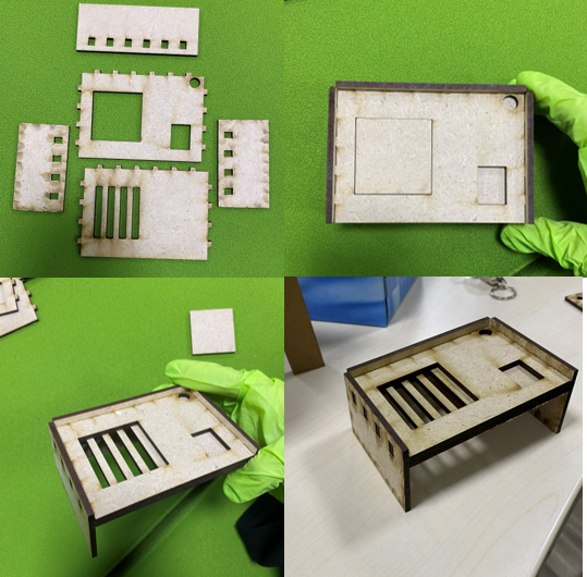
There were some modifications on my table design (Second Design). I didn’t test the design using the Laser cutter machine this time because I already did the test for the previous design which I think is enough to make sure that the pieces are fits to each other because the third design is a modified version from the second design.
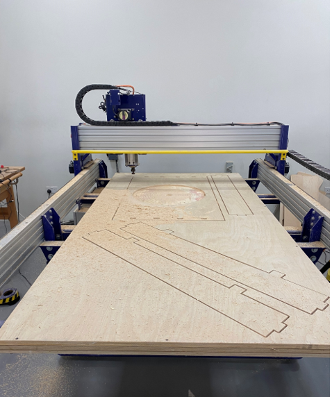
Now the real work is started. The details of what I used is listed below:
18 mm wood
Tool diameter (Milling bit) = 6mm
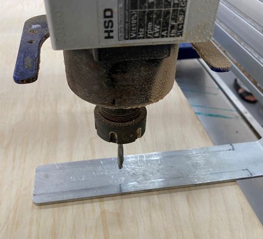
Metal Plate used for Zeroing the z-axis
Caliper to check the Wood Sheet Thickness = 17.90
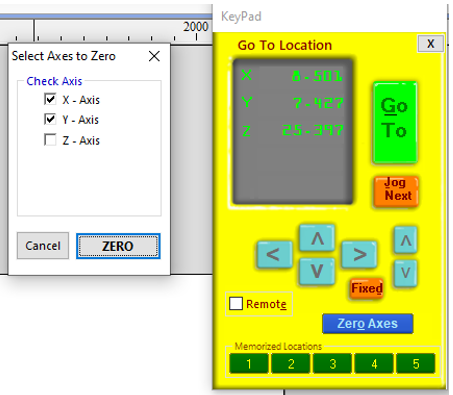
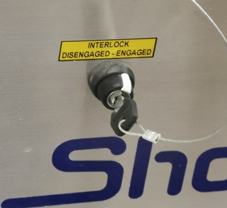
The machine used for this assignment is ShopBot. The machine axis must be set to zero before cutting.
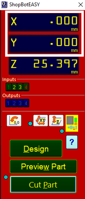
Checking the Milling Bit from Both Sides: Physically confirming the zeroed axis.
Zeroing Z-Axis: To zero the z-axis, the process is different and it requires a clip and a metal plate. The Clip must be connected to a metal part of the machine. The metal part which must be positioned under the milling bit. Once the process of zeroing z-axis is started, the milling bit is slowly moved towards the metal part until it touches it. This way the z-axis is zeroed.
2440 mm x 1220 mm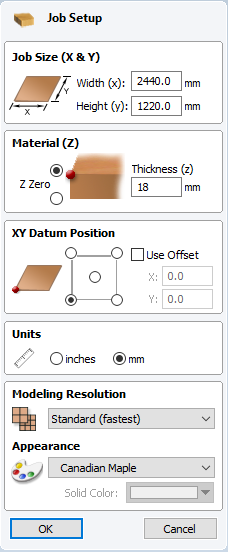
18.2mm.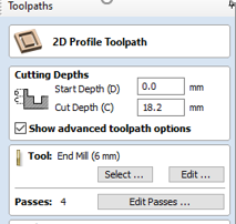
End Mill 6mm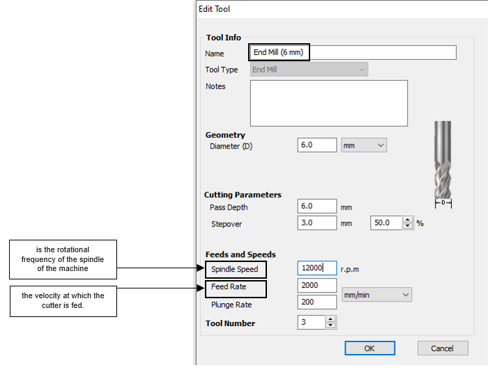
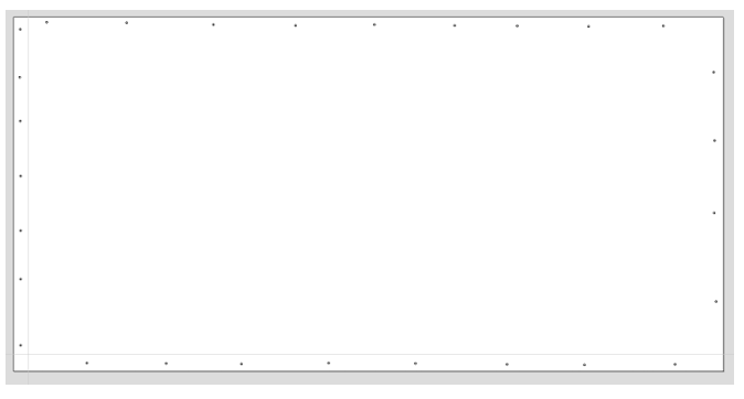
Saving Drill Pathway
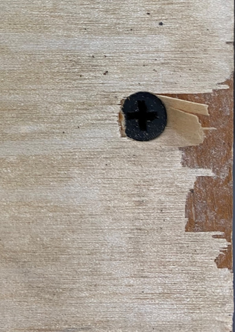
Screw Placed On the Sheet
'Dog-Bone' fillet.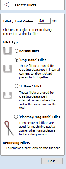
Do Not Forget To Add Tabs As Well: to Prevent Pieces From Flying these tabs secure each object and prevents them from moving out of their place during the milling process.
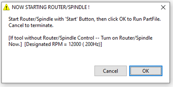
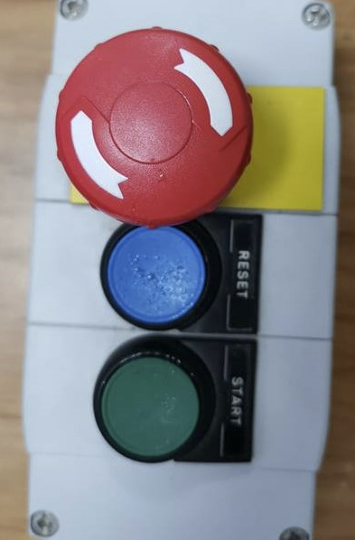
Press “Cut” and Loading Cut Path Files then Press “Start”
Do Not CLICK OK Before STARTING the Spindle!
This week I had many problems. I will list them below.
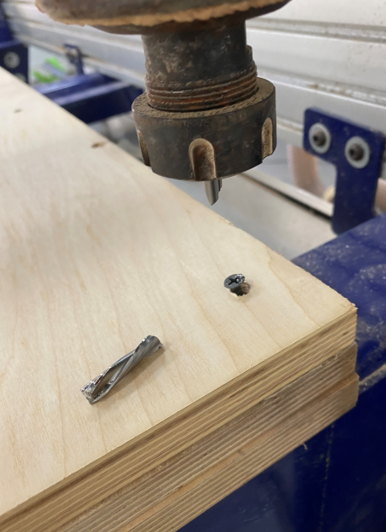
The second problem is that the taps I added were very thin so when I started the operation one of the pieces went to the air so again the milling bit got broken. so I had to add more taps and make sure that the parts will not move.
The third problem is I didn’t clicked on start button after finishing the first part of the operation so again the milling bit got broken for the third time.