Exercise, Week 08 - Embedded Programming
Group Assignment - Compare the performance and development workflows for different microcontroller families
This
is a group assignment done with Ting Kok Eng and Noel Kristian.
Our collective work is documented on the SP Fablab Website Assignment 6 and
hence only my learning and reflections are documented here
Overview of ATtiny45 Microcontroller (1)
The ATtiny45 is a low-power CMOS 8-bit microcontroller based on the AVR enhanced RISC architecture. Executing instructions in a single clock cycle, the ATtiny45 achieves throughputs approaching 1 MIPS per MHz allowing the system designer to optimize power consumption versus processing speed.

The ATtiny45 Microcontroller provides the following features:
· 4K bytes of In-System Programmable Flash for program memory storage, it has an endurance of at least 10,000 write/erase cycles.
· 256 bytes of In-System Programmable EEPROM for data storage (a separate data space) with endurance of at least 100,000 write/erase cycles.
· 256 bytes SRAM (a data memory space)
· 6 general purpose I/O lines,
· 32 general purpose working registers, one 8-bit Timer/Counter with compare modes,
· one 8-bit high speed Timer/Counter,
· Universal Serial Interface,
· Internal and External Interrupts,
· a 4-channel, 10-bit ADC,
· a programmable Watchdog Timer with internal Oscillator, and three software selectable power saving modes.
· using Atmel’s high density non-volatile memory technology.
· Idle mode stops the CPU while allowing the SRAM, Timer/Counter, ADC, Analog Comparator, and Interrupt system to continue functioning.
· Power-down mode saves the register contents, disabling all chip functions until the next Interrupt or Hardware Reset.
· ADC Noise Reduction mode stops the CPU and all I/O modules except ADC, to minimize switching noise during ADC conversions.
· The device is manufactured The On-chip ISP Flash allows the Program memory to be re-programmed In-System through an SPI serial interface, by a conventional non-volatile memory programmer or by an On-chip boot code running on the AVR core.
· The ATtiny45 AVR is supported with a full suite of program and system development tools including: C Compilers, Macro Assemblers, Program Debugger/Simulators and Evaluation kits.
AVR Core Architecture (1)
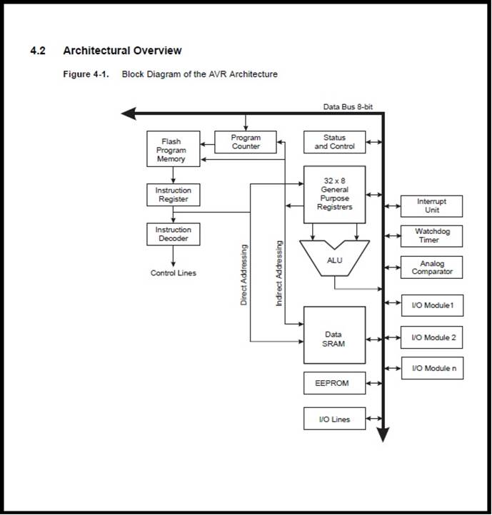
AVR core architecture in general, the main function of the CPU core is to ensure correct program execution. The CPU must therefore be able to access memories, perform calculations, control peripherals, and handle interrupts. In order to maximize performance and parallelism, the AVR uses a Harvard architecture with separate memories and buses for program and data. Instructions in the Program memory are executed with a single level pipelining. While one instruction is being executed, the next instruction is pre-fetched from the Program memory. This concept enables instructions to be executed in every clock cycle. The Program Memory is In-System Reprogrammable Flash memory.
Architecture of ATtiny45 microcontroller (1)

The block diagram showed the functional internal architecture of the ATtiny45 microcontroller.
The AVR core combines a rich instruction set with 32 general purpose working registers. All 32 registers are directly connected to the Arithmetic Logic Unit (ALU), allowing two independent registers to be accessed in one single instruction executed in one clock cycle. The resulting architecture is more code efficient while achieving throughputs up to ten times faster than conventional CISC microcontrollers.
Pin Configurations of ATtiny45 Microcontroller (1)

Supply voltage for ATtiny45 is connected to VCC pin (5 volts) supply and GND pin (0V or ground). Reset input at a low level for longer than the minimum pulse of 2.5μs will generate a reset, even if the clock is not running and provided the reset pin has not been disabled. Shorter pulses are not guaranteed to generate a reset. The reset pin can also be used as a (weak) I/O pin.
The ATtiny45 microcontroller has four sources of reset:
· Power-on Reset. The MCU is reset when the supply voltage is below the Power-on Reset threshold (VPOT).
· External Reset. The MCU is reset when a low level is present on the RESET pin for longer than the minimum pulse length.
· Watchdog Reset. The MCU is reset when the Watchdog Timer period expires and the Watchdog is enabled.
· Brown-out Reset. The MCU is reset when the supply voltage VCC is below the Brown-out Reset threshold (VBOT) and the Brown-out Detector is enabled.
Port B is a 6-bit bi-directional I/O port with internal pull-up resistors (selected for each bit). The Port B output Buffers have symmetrical drive characteristics with both high sink and source capability. As inputs, Port B pins that are externally pulled low will source current if the pull-up resistors are activated.
Alternate Function of Port B (PB0 to PB5) (1)

The Port B pins are tri-stated when a reset condition becomes active, even if the clock is not running Port B also serves the alternate functions of various special features.
On-chip Oscillator (1)
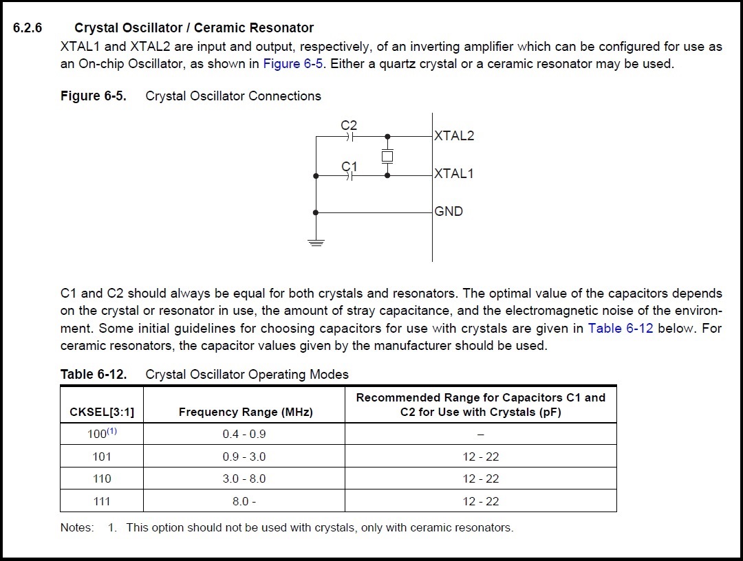
XTAL1 and XTAL2 are configured (as a clock pin, the pin cannot be used as an I/O pin) to use with an on-chip oscillator, either a quart crystal or ceramic resonator. And C1 and C2 are capacitors, typical value used are 22pF.
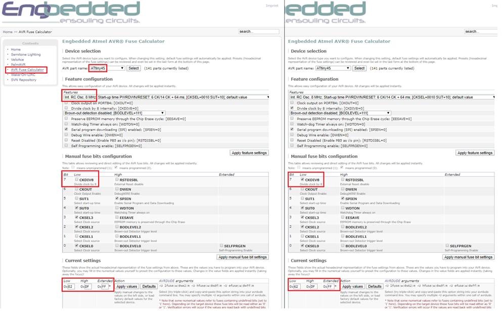
Setting Internal RC Oscillator 8 MHz to Internal 1 MHz System Clock (1)

The device is shipped with CKSEL = “0010”, SUT = “10”, and CKDIV8 programmed. The default clock source setting is therefore the Internal RC Oscillator running at 8 MHz with longest start-up time and an initial system clock prescaling of 8, resulting in 1.0 MHz system clock. This default setting ensures that all users can make their desired clock source setting using an In-System or High-voltage Programmer.
In-System Re-programmable Flash Program Memory and SPI Serial Interface (1)

ATtiny45 is manufactured using Atmel’s high density non-volatile memory technology. The On-chip ISP Flash allows the Program memory (with 4K bytes Flash memory) to be re-programmed In-System through an SPI serial interface, by a conventional non-volatile memory programmer or by an On-chip boot code running on the AVR core.
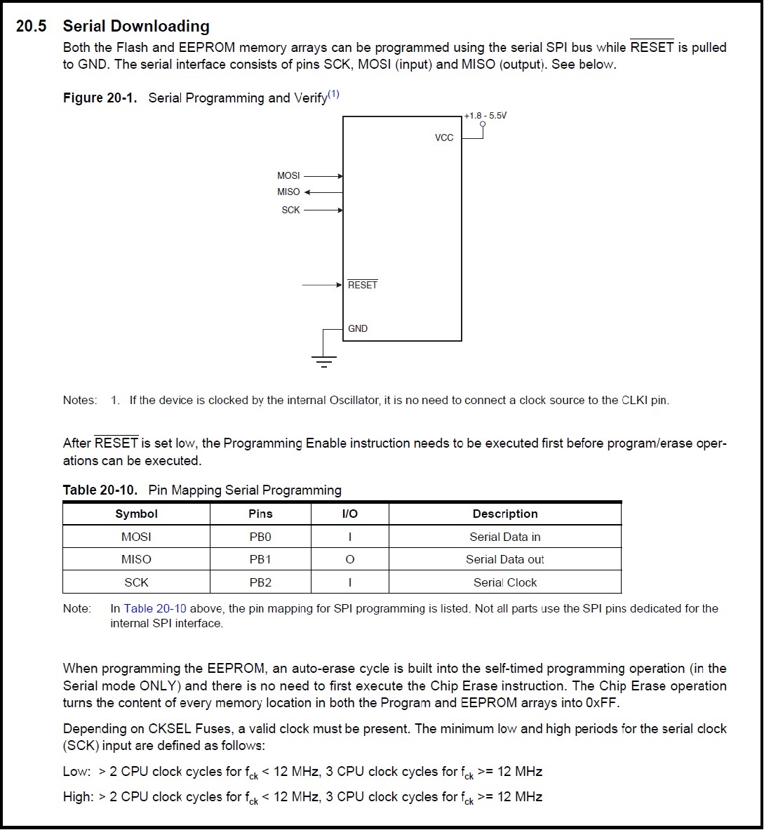
SPI serial interface RESET, SCK, MISO and MOSI from an ATtiny45 microcontroller to program the chip;
Port B, Bit 5 (PB5) – RESET
· RESET: External Reset input is active low and enabled by unprogramming (“1”) the RSTDISBL Fuse. Pullup is activated and output driver and digital input are deactivated when the pin is used as the RESET pin.
Port B, Bit 2 (PB2) – SCK (Serial Clock Input)
· SCK: Master Clock output, Slave Clock input pin for SPI channel. When the SPI is enabled as a Slave, this pin is configured as an input regardless of the setting of DDB2. When the SPI is enabled as a Master, the data direction of this pin is controlled by DDPB2. When the pin is forced by the SPI to be an input, the pull-up can still be controlled by the PORTB2 bit.
Port B, Bit 1 (PB1) – MISO
· MISO: Master Data input, Slave Data output pin for SPI channel. When the SPI is enabled as a Master, this Pin is configured as an input regardless of the setting of DDB1. When the SPI is enabled as a Slave, the data direction of this pin is controlled by DDB1. When the pin is forced by the SPI to be an input, the pull-up can still be controlled by the PORTB1 bit.
Port B, Bit 0 (PB0) – MOSI
· MOSI: SPI Master Data output, Slave Data input for SPI channel. When the SPI is enabled as a Slave, this pin is configured as an input regardless of the setting of DDB0. When the SPI is enabled as a Master, the data direction of this pin is controlled by DDB0. When the pin is forced by the SPI to be an input, the pull-up can still be controlled by the PORTB0 bit.
An ISP 6-pin (2x3) cable can be used to connect these pins (RESET, SCK, MISO, MOSI, VCC and GND) to an ISP programmer to program this chip.
Written a LED blinking program for ATtiny45 in Arduino on Windows (Arduino IDE) (2)

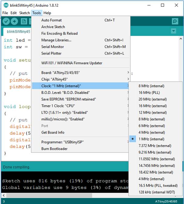
Setting for ATtiny45 in Tools menu.
Select Tools>Boards: "ATtiny25/45/85"
Select Tools>Chip: "ATtiny45"
Select Tools>Clock: "1 MHz"
Changing internal clock to 1 MHz, need to divide ATtiny45 clock by 8 using Burn Bootloader.

Select Burn Bootloader for clock at 1 Mhz.
Reference from AVR Fuse Calculator for ATtiny45 http://www.engbedded.com/fusecalc

Compiling this program. Select Sketch>Verify/Compile

Done compiling, ATtiny45 contain 4K bytes of In-System Programmable Program Memory Flash (1), and this program uses 816 bytes in Arduino on Windows (Arduino IDE).

Uploading this compiled program using programmer. Select Sketch>Upload Using Programmer.
Video of a LED blinking program for ATtiny45 in Arduino on Windows (Arduino IDE).
Written a LED blinking program in Arduino on Windows (Arduino IDE) using AVR libraries


Setting for ATtiny45 in Tools menu.
Select Tools>Boards: "ATtiny25/45/85"
Select Tools>Chip: "ATtiny45"
Select Tools>Clock: "1 MHz (internal)"
Changing internal clock to 1 MHz, need to divide ATtiny45 clock by 8 using Burn Bootloader.

Select Burn Bootloader for clock at 1 Mhz.
Reference from AVR Fuse Calculator for ATtiny45 http://www.engbedded.com/fusecalc


Compiling this program. Select Sketch>Verify/Compile

Done compiling, ATtiny45 contain 4K bytes of In-System Programmable Program Memory Flash (1), and this program uses 76 bytes in Arduino on Windows (Arduino IDE) using AVR library. Included AVR libraries, Sketch use less program storage space because Arduino libraries
are not included in this program.

Uploading this compiled program using programmer. Select Sketch>Upload Using Programmer.
Video of a LED blinking program for ATtiny45 in Arduino on Windows (Arduino IDE) using AVR libraries
Written a LED blinking program using text editor and run with avgcc command line

Copy ATtiny45 file t45gcc.c and t45gcc.make into a avrgcc folder.

In command line, at45gcc.c and t45gcc.make are inside avrgcc folder.
Next creating a makefile. Command line: copy t45gcc.make to makefile.

Using Notepad++ to see makefile.

The process will be automate by creating a makefile and
putting our commands here. Because the utility make reads
automatically a makefile file in the folder where we launch it (3)(4).

Run the makefile. Command line: make
ATtiny45 contain 4K bytes of In-System Programmable Program Memory Flash (1),
and this program uses 76 bytes of AVR memory with AVRGCC command line.

And the .hex is generated in the directory.
Understand the Commands in makefile (5)

AVR-gcc inside the makefile is called to compile the program,
this will make a .out and .hex file (and automatically links in
the standard c library and avr library things)

avr-objcopy inside the makefile convert the information from .bin into .hex file.
Each compilation produces an object file corresponding to the source file, this
are linked (including libraries) together to produce the new executable .hex file (5).
Programming the Chip (5)

The utility called avrdude can program ATtiny45 microcontroller using the
contents of the .hex file specified on the command line. With the command,
the file .hex will be burned into the flash memory. The -p t45 option lets avrdude
know that we are operating on an ATtiny45 chip. Note that full-length names
are also acceptable (i.e. t45 equals attiny45) (6).
Workflow using AVR GCC in command line;
1. User creates the C-source code file using a text editor.
2. AVR-gcc is called to compile the program to object code.
3. A .hex binary file is created.
4. Avrdude is used to upload the program (as a .hex file) to the microcontroller.
Source Codes for ATtiny 45 Microcontroller
1. LED blinking program for ATtiny45 in Arduino on Windows (Arduino IDE), right mouse click and save link: wk08blinkSWtiny45.ino
2. LED blinking program for ATtiny45 in Arduino on Windows (Arduino IDE) using AVR libraries, right mouse click and save link: wk08ArdrinoAVRlib.ino
3. LED blinking program using text editor and run with avgcc command line, right mouse click and save link: t45gcc.c
What I have learned:
1. Data sheet for ATtiny 45 microcontroller provided extensive information about the technical specifications of its performance, characteristics, parameters, part's functionality and the instructions on using it.
2. Arduino core support many microcontrollers.
3. Arduino program use less memory when AVR libraries are included.
4. makefile automate compiling process.
Citation
1. Reference from URL on 23/03/2020: https://ww1.microchip.com/downloads/en/DeviceDoc/Atmel-2586-AVR-8-bit-Microcontroller-ATtiny25-ATtiny45-ATtiny85_Datasheet.pdf
2. Reference from URL on 23/03/2020: https://www.arduino.cc/en/Main/Software
3. Reference from URL on 23/03/2020: http://academy.cba.mit.edu/classes/embedded_programming/hello.ftdi.45.port.make
4. Reference from URL on 23/03/2020: https://www.gnu.org/software/make/manual/html_node/Preparing.html#Preparing
5. Reference from URL on 23/03/2020: https://blog.podkalicki.com/how-to-compile-and-burn-the-code-to-avr-chip-on-linuxmacosxwindows/