Exercise, Week 06 - Electronics Design
Group Assignment - Use the test equipment in my Fablab to observe the operation of an ATtiny45 microcontroller circuit board
This
is a group assignment done with Ting Kok Eng and Noel Kristian.
Our collective work is documented on the SP Fablab Website Assignment 4 and
hence only my learning and reflections are documented here
What I have learned:
1. A digital multimeter can quickly measure voltages, currents and resistance, and some digital multimeters can measure capacitance and inductance.
2.Using a regulated power supply, limit current and set voltage to the required level before connecting it to my microcontroller circuit board.
3. An oscilloscope can display and allow users to analyse the waveform of electronic signals.
Redraw an echo hello-world board using ATtiny45 microcontroller
1. Using Eagle, I had created an echo hello-world board using an ATtiny45 microcontroller, added a button and a LED with current-limiting resistor. Checking my works in Eagle with DRC for schematics and ERC for PCB design,
2. Generate gcode and milled my design with STEPCRAFT 420.
3. Assemble my milled PCB.
4. And, test it with Arduino on Windows
Created an ATtiny45 microcontroller schematics using Eagle


Download the library file fab.lbr from FabAcademy Github and
add it into EAGLE. Using Eagles, rename library fab to 00fab.
Select Library>Open library manager>Browse and select 00fab, click Use.

Select Library>Open library manager.
Select In Use>SparkFun-Aesthetics.
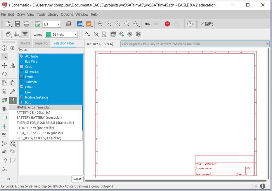
Select Add Part>FRAME_A_L (frames.lbr)
Components used in eagle schmatics;
1. 1 x ATtiny45 microcontroller (SOIC8)
2. 2 x 10 KOhm (SMD 1206)
3. 1 x 1 KOhm (replaced with 0 Ohm SMD 1206)
4. 1 x 499 Ohm (SMD 1206)
5. 1 x Green LED (SMD 1206)
6. 1 x 1 uF (SMD unpolarised capacitor)
7. 1 x push button (4 pins SMD push button)
8. 1 x AVRISPSMD
9. 1 x FTDI SMD header

Adding component. Select ADD>ATTINY45SI (00fab.lbr is at the
top of the list) to the schematics.

Adding 4 resistor to the schematics.

Adding a LED to the schematics.

Adding a 1 uF capacitor to the schematics.

Adding a 4 pins SMD push button switch to the schematics.

Adding a AVRISPSMD to the schematics.
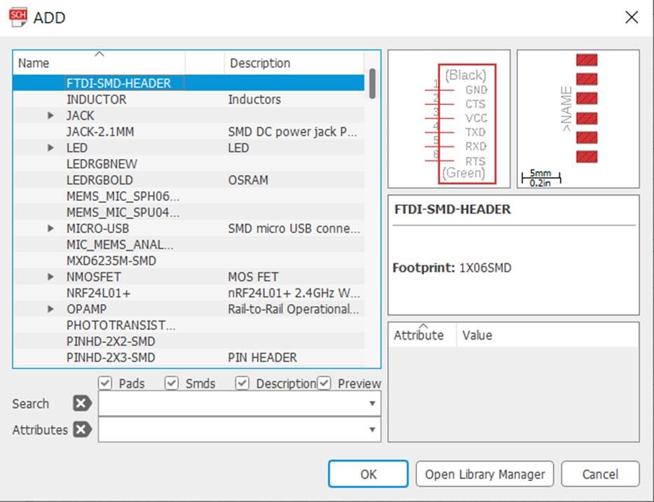
Add a FTDI SMD header to the schematics.

Adding VCCs to the schematics.

Adding Grounds to the schematics.
Connect the components using Nets.

In Schematic Menu, select Tools>ERC
Electrical Rule Check (ERC) command is used to test schematics
for electrical errors, is also performs a consistency check between
a schematic and the actual signal connections in the board. The
result of the check is presented in the ERRORS dialog.

There is no ERC errors or warnings, board and schematics are consistent.
This is my schematics file, right mouse click and save link: wk06ATtiny45v3.sch

Select Generate/switch to board.
Created an ATtiny45 microcontroller PCB using Eagle.


In Board Menu, select Tools>DRC
Setting Design Rules to define all the parameters that the board layout has to follow.

Select Tools>DRC. Set Clearance to 12mil. In Design Rule window,
I had set minimum clearance between objects in signal Layer to 12mil.
This setting of clearance is required for milling process.
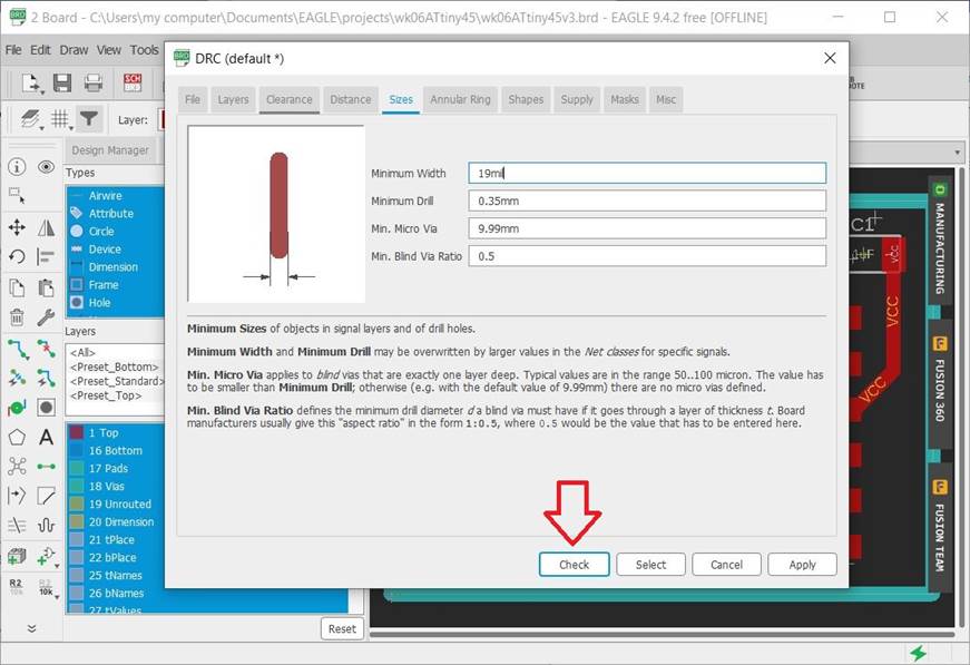
I had set minimum sizes of objects in signal layers (i.e. trace width
sizes) to 19mil. I am using 19mil trace width in my board to ensure
the desired amount of current can be transported easily. Next, select
Click Check button to perform Design Rules Check.

There is no DRC errors or warnings, board and schematics are
consistent. Design Rule Check (DRC) checks the board against
Design Rules and reports any violations. Set board outlines and
arranged the components position for easy routing, select Route Airwire.

In Board Menu, select Tools>ERC
Again, using ERC to performs a consistency check between
a schematic and the actual signal connections in this board.

There is no ERC errors or warnings, board and schematics are consistent.
This is my PCB design file, right mouse click and save link: wk06ATtiny45v3.brd

Generate gcode using Mods

Milling my design with STEPCRAFT 420.

Milled my PCB and assembled the board.
Using Arduino IDE to Program ATtiny45

In Arduino IDE menu, select Tools>Board>ATtiny25/45/85.
This set Arduino IDE to program ATtiny45 microcontroller.

Select Sketch>Verify/Compile to compile the program.

Select Sketch>Upload to load the program into ATtiny45 microcontroller board.
Program Code for ATtiny45

This is the Arduino program code for my ATtiny45 microcontroller.
Right mouse click and save link: wk6t45_hello_demo.ino
Description of Program Code
1. The green LED is initial turn off, a counter (state) is 0.
2. When the push button switch is pressed first time, the counter is 1 and the LED will turn on.
3. When the push button switch is pressed a second time, the counter is 2 and the LED will blink slowly.
4. When the push button switch is pressed a third time, the counter is 3 and the LED will blink very fast.
5. When the push button switch is pressed a fourth time, the counter is reset to 0 and the LED will turn off.
Video for Testing ATtiny45 Microcontroller Board